2018 International Conference on Computer, Communication and Network Technology (CCNT 2018) ISBN: 978-1-60595-561-2
Multi-interface Gateway Protocol Conversion Method for
Nearspace-air-vehicle-ground Dedicated Network
Shi-ji MA and Feng LIU
School of Electronic and Information Engineering, Beihang University, Beijing, China
*Corresponding author
Keywords: Multi-interface bus, Protocol conversion, Gateway, Software and hardware collaboration.
Abstract. There are many kinds of monitoring and detecting load equipments in the Nearspace-air-vehicle-ground network, including visible light, infrared pods and various sensors, and there are various bus interfaces for communication and transmission of different types of loads, including network port, RS422, CAN, LVDS and so on. This paper proposes the use of FPGA and embedded Linux system software and hardware cooperation method to achieve interoperability between multi-bus interface and Ethernet, making full use of software flexibility and hardware fast forwarding capabilities. The test results show that this method realizes the data transmission between the multi-interface bus and Ethernet, and plays an important role in the transmission of information between the landing platform and ground in the Nearspace-air-vehicle-ground Dedicated Network
Introduction
The railway of our country enters the key period of realizing modernization construction,
especially under the “One Belt and One Road” strategic development, the rapid development of the western outlying areas and heavy-load railways has put forward new and higher requirements for integrated railway operation and security technology. However, the current technology measure is single-functioned and regionally independent, and does not constitute a comprehensive, full-featured monitoring system, resulting in an extreme lack of capacity for large-scale monitoring, global situation sharing, and comprehensive decision support for transport management. It is imperative that through the breakthrough of new technologies, it is possible to realize the comprehensive support capabilities for operation and safety of railways covering a wide range, full coverage, and holography.
There are many kinds of monitoring and detecting load equipments in the Nearspace-air-vehicle-ground network, including visible light, infrared pods and various sensors, and there are various bus interfaces for communication and transmission of different types of loads, including network port, RS422 CAN LVDS and so on. The information of all loads in the network including video, images, texts, and instructions are parsed on the servers in the terrestrial LAN. Therefore, a gateway device is required to unify the data frames transmitted by different bus interfaces into Ethernet data packets. The land network transmits in the Nearspace-air-vehicle-ground Dedicated Network and eventually arrives at the ground-side server to extract the bus data frames.
In order to solve the above problem, this paper proposes a method of hardware and software cooperation between FPGA and embedded Linux system to realize the protocol conversion between multi-bus interface and Ethernet [4]. FPGA is responsible for transceiving the data frame of bus interface and implement protocol conversion in embedded system software. The protocol conversion of multi-interface data frames and Ethernet data packets makes full use of software flexibility and hardware fast forwarding capabilities.
Protocol Conversion Method Research
Research Status
At present, there are mainly three methods for implementing a protocol conversion gateway:
i. ARM-Based Multi Protocol Conversion Method for Embedded Gateway. For example, Yan Lianlong analyzed some key technologies for building embedded gateways. Based on the analysis of some embedded technologies, he proposed a design scheme for embedded gateways and realized the protocol conversion between CAN, RS-485 and the Internet, and gives a concrete realization[5].
ii. Design of protocol converter based on single chip microcomputer. For example, a CAN-to-Ethernet protocol converter was designed for the remote monitoring of CAN-based industrial control systems via Ethernet [6]. The protocol of TCP/IP transport layer chooses UDP protocol, realizing the conversion between CAN and UDP protocol with the one-chip computer.
iii. FPGA—based protocol conversion gateway design. The gateway can convert CAN, RS232, RS485, Zigbee and other protocol data to Ethernet data to achieve information sharing among multiple devices [7]. The conversion module is based on FPGA, which improves data processing and conversion efficiency and solves the problem of low data conversion efficiency of different protocols [8].
In the current bus protocol conversion gateway research, one-to-one protocol conversion research is more and the object is mostly between computers, through special protocol chips and the use of high-performance processors for different protocol data packets Diagnostic information is processed and the protocol is finally converted. Since the targets of the gateway equipment under the Nearspace-air-vehicle-ground Dedicated Network are the load devices and various sensors, the interfaces are diverse and the number is relatively large. The current gateway-oriented objects are mainly the communication of multi-bus interfaces between computers, so they cannot directly be used in ourNearspace-air-vehicle-ground Dedicated Network.
Method Design
Figure 1. Multi-interface gateway protocol conversion components.
Figure 2 is a schematic diagram of the gateway multi-interface protocol conversion under the Nearspace-air-vehicle-ground Dedicated Network. The three bus interfaces are RS422, CAN, and LVDS. The FPGA multi-interface processing unit include bus a transceiver module and a framing module, embedded protocol conversion module. switch chip forwarding module, including switching chip and PHY chip. The cores of this solution are the FPGA multi-interface processing unit and the embedded protocol conversion module, which complete the protocol conversion downlink, that is the protocol conversion between the bus interface to the Ethernet, and the protocol conversion uplink, that is the protocol conversion between the Ethernet to the bus interface. According to the characteristics of each bus transmission rate, RS422 is 10Mbps, CAN is 1Mbps, and LVDS is 655Mbps-1.923Gbps, which can be used to transmit text, command, and video services respectively. The local server receives the data packet and parses the video, text, and instructions.
Figure 2. Schematic diagram of the multi-interface gateway protocol conversion method.
Hardware Design
Multi-interface gateway protocol conversion scheme design circuit schematic shows in Figure 3, Freescale P1022 embedded processor, Xilinx XC7K325TFBG900 FPGA chip, BCM56344 switching chip and BCM54240 PHY chip. Two CAN interfaces, connecting PCA82C250 transceiver and SJA1000T controller between CAN bus and FPGA; two RS422 interfaces, connecting TXB0108PWR level-shifting chip between RS422 and FPGA; four LVDS interfaces, connecting Differential driver between LVDS and FPGA. The PCIE bus is connected between the embedded processor and the FPGA and the switching chip, the switching chip and the FPGA are configured under the embedded linux system. By using a switching chip, the packet forwarding rate of the entire system can be effectively improved.
Multi-bus interface
Bus transceiver module
Framing module Embedded Protocol
Conversion Module
Switch chip forwarding module Ethernet transceiver
[image:3.612.87.533.453.589.2]Figure 3. Multi-interface gateway protocol conversion design circuit schematic.
Protocol Conversion Implementation
Main Module Implementation
Multiple Bus Interfaces. The multi-bus interface includes RS422 serial port, CAN bus, and LVDS. Since the external bus interface for monitoring loads under the landing platform is diverse, and different bus interfaces have different transmission rates, can be transmitted images, videos, texts, instructions, and other data through the interfaces. The scheme is designed with two RS422 interfaces, two CAN interfaces and four LVDS interfaces, which can realize simultaneous transmission of multiple load devices.
[image:4.612.112.499.476.716.2]Bus Transceiver Module. The function of the bus transceiver module is to receive various data frames from multiple bus interfaces, different interfaces are prioritized, LVDS priority is 1 (highest priority), RS422 priority is 2, CAN priority is 3; The data of each device is sent to the framing module in order in which the child device numbers are identified, so that the multi-path devices can simultaneously perform communication transmission and improve the transmission efficiency.
Figure 4. Bus transceiver module workflow. Figure 5. Protocol conversion module workflow.
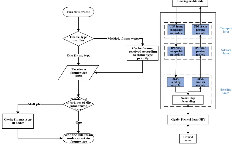
The workflow of the bus transceiver module is described as follows: Bus data frame
Frame type number Receive a frame type data Cache frames, received according
to frame type priority Multiple frame types
Number of interfaces of the
same frame type
Send the sub-frame under a certain
frame type One Cache frames, sent
in order Multiple
One frame type
Transport layer Network layer data link layer Framing module data
UDP frame encapsulati on module UDP frame parsing module IP frame encapsulati on module IP frame parsing module MAC sending module Switch chip forwarding
Gigabit Physical Layer PHY
Ground server
i. The bus interfaces are connected to different types of load devices. Under the same interface type, multiple sub-devices are connected. The device sends bus data frames according to the bus interface frame format.
ii. Determine the number of frame types using several different interfaces for data transmission. If there are multiple frame types, data is put into the cache and received according to the frame type priority.
iii. Determine the use of several interfaces for data transmission in the same frame type. If multiple interfaces are used, the data is put into the cache, and the subinterface ID tag is marked in sequence to send to the framing module.
Framing Module. If we only use one interface of one frame type for data transmission, we need to take n (default 8 bytes) bytes data and add the frame header ID;
[image:5.612.72.470.621.690.2]If we use multiple interfaces of one frame type for data transmission, we need to perform framing transmission on the data of each sub-interface separately.
Table 1. Bus frame data framing.
ID01 Data1 ID10 Data1 ID01 Data2 ID10 Data2 … Single/multiple
interfaces 2bit
Interface ID 2bit
Data length
4bit
Data 1 Data 2 Data 3 Data 4 Data n
Single/multiple interfaces: 00 stands for single interface, 01 stands for multiple interfaces, when 00, the interface ID is 00; when it is 01, the interface ID is 00-11;
Interface ID: uses multiple interfaces for data transmission interface identification under the same frame type;
Data length: The data length is n (the default is 8) bytes transmission, and the maximum can be 16 bytes. When it does not satisfy n bytes, padding 0 meets the actual length.
Embedded Protocol Conversion Module. Transfer data of the same interface ID under a frame type to remove the header of the framing, and add 1 byte interface ID in the data part header to identify the interface ID under the original framing module. Using the kernel network protocol stack of the embedded Linux system to complete the encapsulation of UDP, IP, and Ethernet data packets in turn, and send them to the switch chip forwarding module.
Switch Chip Forwarding Module. Select Broadcom's exchange chip BCM56334. BCM56334 is a high-performance switch chip that supports L2/L3. It supports 24 Gigabit Ethernet ports. The switch chip controls the PHY chip to transmit packets at a specified port according to the destination MAC address of the received data packet, improving the forwarding ability. The current exchange chip mac: 0x00.00.00.00.06.27.
Ethernet Transceiver Module. The function of the Ethernet receiving module is to receive the bus interface frame to transmit data in the form of Ethernet data packets, and to receive and aggregate the data transmitted by the same interface ID identifier separately;
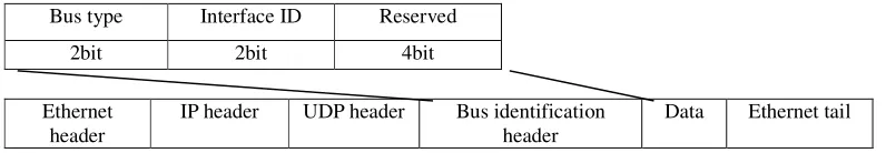
The Ethernet transmission module needs to add a bus identification header in the header of the data area. The bus identification header includes 2 bit bus type, 00 indicates LVDS, 01 indicates RS422, 10 indicates CAN, 2 bit bus ID, and 00 indicates that the device 1, 01 indicates device 2,10 indicates device 3, 11 indicates device 4; 4bit reserved bit for subsequent expansion.
Table 2. Bus identification frame format.
Bus type Interface ID Reserved
2bit 2bit 4bit
Ethernet header
IP header UDP header Bus identification header
Data Ethernet tail
Multi-interface and Ethernet Protocol Conversion
uses standard frames with 11-bit identifiers for transmission. The framing module takes out the data link layer data transmitted by different bus interfaces for framing, and the embedded protocol conversion module sequentially encapsulates the Ethernet data packets through the transmission control layer, the network layer, and the data link layer from the top to the bottom. Through the network cable to the server, from the bottom to the top in order to parse thedata packet, and finally remove the data frames transmitted from different bus interfaces. The process of data transmission from Ethernet packets to multi-bus interface data frames is contrary to the previous ones. It is necessary to fill the bus type and bus ID fields in the raw data part as described in Table [2].
Figure 6. Protocol conversion model.
Test Verification
Testing Scenarios
Figure 7. Multi-interface gateway protocol conversion test schematic.
[image:6.612.83.535.406.624.2]Table 3. Test Examples.
Test case Bus type Bus ID PC2 send data PC1 receive data 1 00(LVDS) 01 1,2,3,4,5,6,7,8 1,2,3,4,5,6,7,8 2 01 (RS422) 01 1,2,3,4,5,6,7,8 1,2,3,4,5,6,7,8 3 10 (CAN) 01 1,2,3,4,5,6,7,8 1,2,3,4,5,6,7,8 4 01 (RS422) 01 1,2,3,4,…16 1,2,3,4,…16
01 (RS422) 10 16,15,14…1 16,15,14…1
Summary
This paper studies the multi-interface gateway protocol conversion and proposes a method of using FPGA and embedded Linux system software and hardware collaboration to realize the communication between multiple bus interfaces and Ethernet. This method makes full use of software flexibility and hardware fast forwarding capabilities. Under the well-established test platform, protocol conversion and transmission of data frames between LVDS-Ethernet, RS422-Ethernet, and CAN-Ethernet is implemented, and the data is parsed correctly locally. The test results show that this method can realize the correct and efficient data transmission between the multi-interface bus and the Ethernet, and plays an important role in the transmission of information between the landing platform and ground in the Nearspace-air-vehicle-ground Dedicated Network.
References
[1]Tristan Glatard, Marc-Étienne Rousseau, Sorina Camarasu-Pop, Reza Adalat, Natacha Beck, Samir Das, Rafael Ferreirada Silva, Najmeh Khalili-Mahani, Vladimir Korkhov, Pierre-Olivier Quirion, Pierre Rioux, Sílvia D. Olabarriaga, Pierre Bellec, Alan C. Evans. Software architectures to integrate workflow engines in science gateways[J]. Future Generation Computer Systems, 2017, 75.
[2]Yang G. Kim, Yu Wang, ByoungSeob Park, Hyo Hyun Choi. A heuristic resource scheduling scheme in time-constrained networks[J]. Computers and Electrical Engineering, 2016, 54.
[3]G.V Vivek, M.P Sunil, Enabling IOT Service Using WiFi-Zigbee Gateway for A Home Automation System, In proceedings of IEEE International Conference on Research in Computational Intelligence and Communication Networks, 2015:77-80.
[4]Shi Yang Yan. Design and Implementation of ZigBee Gateway for Ethernet[J]. Applied Mechanics and Materials, 2014, 3253(571).
[5]Chuan Wu, Zhi Ping Zhou. Design of IOT Gateway System Based on WMMP-T Protocol[J]. Applied Mechanics and Materials, 2014, 3147(548).
[6]Gheorghe G. Florea, Oana I. Rohat, Monica G. Dragan. Contributions to the Development of Communication Protocols Conversion Equipment[J]. IFAC Proceedings Volumes, 2013, 46(6).
[7]Zhang, Hao, Xu, Guangli, Lu, Yang, Lou, Guohuan. Research on the Field Bus Protocol Conversion Gateway[J]. EN, 2012, 7(15).
[8]Hao Zhang, Yanan Li, Huiling Zhu. Development for Protocol Conversion Gateway of Profibus and Modbus[J]. Procedia Engineering, 2011, 15.