2018 International Conference on Physics, Computing and Mathematical Modeling (PCMM 2018) ISBN: 978-1-60595-549-0
Control System for a Mechatronic Object Using Evolutionary Algorithms
Alexander LITVINENKO and Kirill SMETANIN*
Full Russia, Voronezh, Moskovskiy prospect, 14 Russia, Voronezh, Marshala Zhukova, 4 *Corresponding author
Keywords: Articulator, Electric drives, Testing, Mutator.
Abstract. The paper considers development of structure and software of the information diagnostic complex with an articulator for reproducing motions (natural modeling) of the human jaw (object of the original) for the purpose of fitting the dentition into prosthetics. It uses the system of technical vision to determine the object of the original and records the results of processing in the memory block. The testing unit based on evolutionary algorithms allows to minimize the errors of the program, and leads to a reduction in the total number of errors.
Introduction
At present, there is a crucial problem of producing special electromechanical devices for fitting dental rows during prosthetics–namely automatic articulators for the reproduction of movements, referred to as natural modeling of the natural human lower jaw.
For adequate “in-situ” modeling it is necessary to ensure the rigidity of the kinematic chain, and also to provide the control system with a given quality criterion for controlling electric drives. Moreover, the effect of transforming the phase coordinates of the original object into more global (generalized) coordinates of electric drives within the framework of the solution of the inverse positional problem is used as the signal for setting electric drives.
Modeling the Electromechanical System of the Articulator.
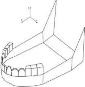
The object of study has six degrees of freedom, i.e. its position is uniquely defined by six coordinates. Thus, after the transformation of coordinates, we have six numbers: three coordinates X, Y, Z and three angles - beta, theta, and gamma. The six coordinates obtained this way are used for computer modeling of object’s movements in the AutoCAD system. For this purpose special Java program was developed.
Figure 1 shows the directions of the X, Y, Z coordinate axes. The digits 1, 2, 3 indicate the reference points.
Figure 1. The model of the original object of a figure caption.
[image:1.595.228.370.593.737.2]important in terms of the mathematical description convenience of the kinematics, as well as due to the increased functionality of the articulator itself.
Figure 2. Kinematic diagram of the articulator.
The importance of naturally practical factors has to be emphasized here: the universality of drives, their low cost, the simplicity of practical linking of the separate elements (links) of articulator, the convenience of using the classical theory to describe kinematics and dynamics.
The complexity of the mathematical description of the kinematics and dynamics essentially depends on the choice of the coordinate system of the links. Denavit-Hartenberg Coordinate System Method proposed in 1955 is the most suitable one in terms of universality of the mathematical description.
Description of the Operation of the Control Device.
In some cases, when manipulation systems are applied, the task signals of the electric drives are not known until the very moment when the reproduction of movements begins. Therefore, the goal is to develop control devices containing blocks for transforming the coordinates of the reference points into more generalized coordinates of the kinematic chain, which would be operating in real time.
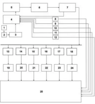
In order implement this task, the device for controlling electric drives of the manipulation system of motion reproduction has been developed. The figure 3 shows the block diagram of the control device. The device consists of the following units: a vision unit 1, a memory block 2, a program reading block 3, a derivative calculator 4, a step calculation unit 5, a decision block 6, a verification unit 7, a test unit, position sensors, engine control units, and the engine of the articulator itself.
The control unit is provided with a ‘cycle end check’ unit, a test unit, a derivative calculation unit, a step calculation unit and a decision unit, whereas the outputs of the ‘program reading’ unit and the ‘position sensors’ are connected to the ‘derivative calculation unit’. The output of the derivative calculation unit is connected to the ‘step calculating unit’, step is connected to the decision block, the decision blocks are connected to the end-of-cycle check blocks with the outputs "yes" and "no", with the output "yes" connected to the drive control unit, and in the "no" output is connected to the unit for calculating the derivative values coefficients from the Taylor series, limited to linear terms.
Segmentation of the Video Image within the Technical Vision System using Brightness
Figure 3. Block diagram of the control device.
Threshold image restriction could be considered a particular method. Many images contain an object of sufficiently homogeneous brightness against the background of a different brightness that interests us. If the object is white and is located on a black background or on the back side, then the definition of the points is achieved by setting the threshold by the average brightness.
The notion of a threshold level (threshold) is tested in the following form:
Т— Т[х, у, р (х, y),f(x, у)] (1) Where f (x, y) is the intensity at the point (x, y), p (x, y) is a local property defined in a neighborhood of this point. The threshold image can be described by the following formula:
1, if f(х, у) > Т
0, if f(x, у) <= Т (2) So that pixels in g (x, y) with a value of “1” correspond to objects, and pixels that have a value of “0” correspond to the background. The equation assumes that the intensity of the objects is greater than the background intensity.
If the value of “T” in equation (1) depends only on f (x, y), then the threshold is called “global”. If the value of T depends both on f (x, y) and on p (x, y), the threshold is called “local”. If, in addition, T depends on the spatial coordinates x and y, in this case it is called the “dynamic” threshold. Global thresholds are used in situations where there is a clear distinction between objects and the background. The methods of inverse and structured illumination usually give images that can also be segmented by applying global thresholds.
The process of interaction of the program modules for identifying the dynamic coordinates of the original object within the user interface, editing the image area is performed using an auxiliary window, which sets the limits for viewing the image on four sides. When you specify borders, all parts of the image that are beyond the specified limits are filled with black color.
After editing the viewing area of the processed image, it is possible to eliminate the noise and to achieve a clear discrimination of the areas of the desired reference points.
The next step of the user after “thresholding” and editing of the image viewing area is to filter candidate areas by size, in order to finally select the reference points that we need. This step is another step in clearing the image from interference.
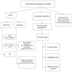
algorithm of filtering “candidate areas” by size is an algorithm for thinning out an image. Figure 4 shows the structure of the information and diagnostic complex.
Figure 4. The structure of the information and diagnostic complex.
Evolution Testing
Testing of the software of the diagnostic complex is carried out using the so called “unit testing approach”. The idea is to write automatic tests for each function or method of the program. This allows us to check, in a fairly short period of time, whether the code change led to regression. As a test framework, the Junit library is selected. Modular testing allows you to make sure that the module still works correctly. The complexity of writing unit tests depends on the code organization itself. A strong link or large area of responsibility for individual entities (classes for object-oriented languages) can complicate testing. The test code is placed in separate catalogues.
For input parameters, the formulas are chosen so that the output of the function test is a simple and understandable number. In a modular test, clearly define the preconditions (initialization of test data, preliminary settings), the action (actually what is being tested) and the post-condition (which appears as a result of the action). Such design increases the readability of the test and makes it easier to use it as an appropriate documentation for the tested functionality.
Quiet similarly the test looks like the following way:
public static void Test_FindingOfReaperDotsForSys() { //arrange var packagesRepositoryMock = _mocks.Create<IPackagesRepository>(); packagesRepositoryMock .Setup(r => r.FindPackageAsync(_packageId)) .Returns(Task<DatabasePackage>.Factory.StartNew(() => null));
Register(packagesRepositoryMock.Object); //act var message = PostChunkTo (new byte[] { 1, 2, 3 }); //assert _mocks.VerifyAll(); Assert.That(result.Status, Is.EqualTo(Status.Sucess)); }
Tests checking the interaction with the program's memory looks the following way:
var finder = new ObjectFinder(fakeIdentifier, ConnectionString); //act var foundObject = finder.Find(); //assert Assert.That(foundObject, Is.Null); }
Determining the quality of tests used in testing the software part is carried out using mutational algorithms according to the following scheme:
Change (“mutation”) is generated at the critical spot of the program. Typical mutations are:
inverting the condition, changing the boundary conditions of the cycle, replacing mathematical operations.
All tests get started (or some of them).
The results are analyzed. If at least one test fails or breaks - a mutant is considered "killed" and
if all tests are green it is considered to be a "survivor". The available mutators are briefly described below:
Mutator of symbols. A conditional boundary mutator replaces relational operators <, <=,>,>
The mutator of conditional expressions will mutate all the conventions found in accordance
with the substitution table below.
Conditional deletion mutator. Removes all conditional statements, so that protected statements
are always executed.
A mathematical mutator replaces binary arithmetic operations for both integer and floating
point arithmetic with another operation.
Growing mutator. It will mutate increments, decrements and increments of assignment and
reduction of local variables (stack variables). It will replace increments by decrements and vice versa.
An inverting negative mutator inverts the negation of integer and floating point numbers.
As a result, the structure and software of the information diagnostic complex with an articulator for reproducing motions (natural modeling) of the human jaw (object of the original) for the purpose of fitting the dentition into prosthetics was developed. It uses the system of technical vision to determine the object of the original and records the results of processing in the memory block. The testing unit based on evolutionary algorithms allows to minimize the errors of the program, and leads to a reduction in the total number of errors.
References
[1]A.S. Anuchin, “Control systems of electric drives,” Vologda: Infra-Engineering, 2015.
[2]Korobiichuk, I.; Podchashinskiy, Y.; Shapovalova, O.; Shadura, V.; Nowicki, M.; Szewczyk, R.
Precision increase in automated digital image measurement systems of geometric values. // Advances in Intelligent Systems and Computing 393 / Warsaw, 2016.
[3]Zakvasov, V. V.; Perekrest, A. L.; Gorbatko, S. V.; Zakvasova, S. V.; Zamariev, G. V. Complex