391 | C i E T V E T 2 0 1 2
Design A System and Database for Automated
Machining Feature Recognition
Chen Wong Keong
Department of Mechanical Engineering, Polytechnic Kuching Sarawak Email: wongk@poliku.edu.my
Associate Professor Dr. Yusri Bin Yusof
Department of Manufacturing and Industry Engineering, Faculty Mechanical & Manufacturing Engineering,
Universiti Tun Hussein Onn Malaysia. E-mail: yusri@uthm.edu.my
Abstract
Computer aided design (CAD) is the earliest stage of the product cycle in a computerised manufacturing environment. CAD has the greatest role in helping to visualise the initial concept of a design with presenting the idea in a graphical view. The advanced of digital computer has eased the work of design drawing with generating the most complete design in 2D (two dimensional) and 3D (three dimensional) views. The generated
drawing from CAD is not the end of the cycle of the product manufacturing process. The selected drawing will be sent to the manufacturing department for manufacturing process. The drawing created by CAD is just the description of geometrical features of the design component. This type of data cannot be used directly for the manufacturing process and normally intervention of human effort is needed to define all the
manufacturing features from the component drawing again. As a result, a new system and database will be proposed. This system which has the ability to extract geometrical features from drawings and identify all the manufacturing features which is useful for manufacturing process. A neutral drawing format (ISO 10303-203) is as the input of the system. Then, a mechanism which consists of manufacturing feature extraction and feature recognition will be implemented and lastly, a new form of manufacturing feature-based data, ISO 10303-224 will be acquired for the subsequent manufacturing process.
392 | C i E T V E T 2 0 1 2
1 Introduction
Computer-aided design system has played a significant role in the process of model design. However, (Xu, 2009) stressed that at present CAD does little in helping a designer in a more creative and intuitive way such as generation of possible design solutions, or in those aspects that involve complex reasoning about the design – for example in assessing, by visual examination of drawing, whether a component may be (easily) made, or whether it matches the specifications. These aspects are, however, subjects of consideration current research. In practicing concurrent engineering, there is a pressing need for CAD systems to interface or integrate design with all the down-stream activities, e.g. manufacturing and marketing.
Over the years, CAD has been undergoing fundamental changes toward the direction of feature-based design or design by features. Commercial implementation of feature-based design (FBD) technique became
available in the late 1980’s (Xu, 2009). One of the main benefits of
adopting feature-based approach is the fact that feature can convey and encapsulate designer’s intents in a natural way. However, such a feature-based design system, though capable of generating feature models as its end result, lacks the necessary link to a CAPP system, simply because the design features do not always carry the manufacturing information which is essential for process planning activities. From conventional CAD models, it only provides pure geometry and topology for mechanical
designs such as vertices, edges, faces, simple primitives, and the relationship among them. Feature recognition is then required to interpret this low-level part information into high-level and domain-specific features such as machining features (Xu, 2009). In essence, feature recognition has become the first task of computer-aided process planning (CAPP) system. It serves as an automatic and intelligent
interpreter to link CAD with CAM, regardless of the CAD output being a pure geometric model or a feature model from FBD system (Xu, 2009). To be specific, the goal of feature recognition system is to bridge the gap between a CAD database and a CAPP system, and based on the
recognized feature, to drive the CAPP system which produces process plans for manufacturing the part. Human interpretation of translating CAD data into technological information required by a CAPP system is thus minimized if not eliminated. The input of an automatic feature recognition system is often a conventional description of the geometry of a part, i.e. a geometric model. The output is a list of recognized instances of features with necessary technological parameters and their proper organisation (Xu, 2009).
Many attempts have been made to classify feature recognition systems. One of the most common ways to classify them based upon the actual techniques used by the systems. Some of these techniques are known as, syntactic pattern recognition approach, geometric decomposition
approach, expert system rule/ logic approach and graph-based approach. In the manufacturing domain, feature recognition approaches can also be classified for recognising rotational (turning) features and approaches for recognising non-rotational (milling) features. In the shape domain,
feature recognition approaches can be classified as prismatic, rotational, flat and uniform cross section features as shown in table 1.
(Shah & Mantyla, 1995) classified automatic feature recognition
393 | C i E T V E T 2 0 1 2
hull and decomposition are the three methods for machining region recognition. Meanwhile, pre-defined feature recognition can be further classified into boundary based and volume based feature recognition. Syntactic, rule, graph-based and neural net are normally methods
adopted for boundary based pre-defined automatic feature recognition.
2 Feature Creation Techniques
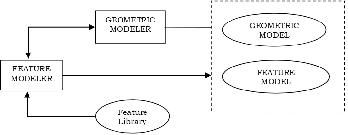
It is convenient to look at the total feature-based model as consisting of two interrelated components, namely a feature model and a geometric model as shown in figure 2. Even if there is no physical separation between the two models, we can view the data conceptually as being of two types. The geometric model contains a boundary representation, CSG, or other geometric representation of the object. The feature model contains the clustering information, feature properties, relationships of interest, and other higher level data (Shah & Mantyla, 1995).
Many alternative techniques have been devised for creating feature-based models. these techniques can be divided into two main categories based on whether features are extracted from geometry (FfG), or on whether geometry is created from the feature (GfF). Traditionally the FfG methods are called feature recognition, while GfF methods are called design by features. FfG may be automated by means of computer algorithms, or it may be necessary for the user to perform the task. The formers is labelled automatic feature recognition, while the latter is called human-assisted (or interactive) feature recognition (Shah & Mantyla, 1995).
The procedure followed in creating feature models, in each of the above cases, can be described as follows:
i. Interactive feature recognition. A geometric model is created first, then features are created by human users, such as by picking entities in an image of the part (Figure 3). User1 and User2 may be the same person.
ii. Automatic feature recognition. A geometric model is created first, then a computer program process the resulting model to automatically find features (Figure 4).
iii. Design by features. The part geometry is created directly in terms of features; geometric models are created from the features (Figure 5).
2.1 Interactive Feature Creation
Although the interactive feature creation approach was originally developed to provide feature data for process planning before the availability of design by feature systems, it continues to find uses
because of its simplicity. In this approach the geometric model is created first, using a solid (or two-dimensional drafting-type) geometric modeler. After exiting the geometric modeler, the geometric model file is sent to an interactive graphics program that renders an image of the part in order to let a user view the geometry and create features on it. The user can
394 | C i E T V E T 2 0 1 2
as tolerances, finish or high-level nominal parameters (e.g., hole diameter) (Shah & Mantyla, 1995).
In its simplest form, interactive feature creation can be just adhoc
grouping of geometric entities by the user, with some user-specified data added; the resulting model is aimed specifically for use by some
application program. It is entirely the user’s responsibility to ensure that the feature model is valid and complete. All that is needed to implement such a system is to record pointers to the entities picked and associate them with a feature name and other data, specified by the user. Such representation may be specially geared to a specific application program (Shah & Mantyla, 1995).
2.2 Automatic Feature Recognition
Various techniques have been developed to provide, without any human intervention, the product data input needed by applications such as process planning, NC part programming, and inspection planning. This is popularly referred to as feature recognition, although the output of some techniques is not in the form of features but rather as machining
volumes. These latter methods typically assume that all machining will be done by milling, so it is not necessary to know the specifics of a feature other than its boundaries corresponding to find machined surfaces. For example, it does not matter if a machining volume is a rectangular pocket or an L-shaped slot because tool paths can be generated without this distinction. For this reason we classify these methods into two groups: machining region recognition and pre-defined feature recognition (Shah & Mantyla, 1995).
2.3 Machining Region Recognition
Machining region recognition methods were devised for generating NC tool paths directly from CAD databases. The objective of these algorithms is to determine volumes that need to be removed by machining, usually by end milling. There is no comparison made to pre-defined shapes. Machining region recognition techniques may be classified into three categories (Shah & Mantyla, 1995):
i. Sectioning
ii. Convex hull decomposition
iii. Cell decomposition
395 | C i E T V E T 2 0 1 2
Convex hull decomposition is used to decompose a volume into convex machining volumes. The part is first subtracted from its convex hull, and the process is repeated until each volume is equal to its own convex hull (Shah & Mantyla, 1995).
3 An Integrated, STEP-Compliant Manufacturing Environment STEP, the Standard for the Exchange of Product Model Data, is a large and powerful set of International Organisation for Standardisation (ISO) standards, all under ISO 10303. The overall objective of STEP is to provide a mechanism that describes a complete and unambiguous product definition throughout the life cycle of a product. STEP provides both broadly useful data modelling methods and data models focused on specific industrial uses. The STEP standards contain several dozen
separate documents (Kramer & Xu, 2009).
STEP-based manufacturing is currently a hot topic to discuss. The first major challenge in STEP-based manufacturing system is to establish a concurrent engineering environment across all manufacturing activities. A key element in this environment is feature which allows integration between CAD (as in AP203) and CAPP (as in AP224 and AP238) data. However, recognizing AP224 features from an AP203 model is still being research (Zhao, Habeeb, & Xu, 2009).
Figure 6 shows an integrated STEP-compliant manufacturing system. The geometric representation data described in AP203 or other formats are translated into machining features defined in AP224. The machining feature definitions are used as inputs to macro process planning
applications (Examples: AP240 for machining, AP223 for casting, and AP229 for forging). Micro process planning for machining (AP238) and inspection (AP219) are then carried out for each of the aforementioned application processes. In such a system, the need for data conversion is eliminated (Zhao, et al., 2009).
STEP AP203 is just one of the neutral data format which is always used in intergrading between different CAD systems that shown in figure 1. Besides, IGES and ACIS have also the similar functions as STEP AP203. However, these types of neutral format cannot be used directly for further manufacturing process without translating them to a more meaningful high level data. Feature technology is the solution for translating these geometrical format data to manufacturing feature-based data, which is defined in AP240, which is useful for manufacturing process.
AP224 was developed to bridge the gap between CAD and CAPP by
providing machine part information that ensure the design information is at the same time 100-percent complete, accurate, computer-interpretable and reusable. Thus, automated process planning from product data in a digital format is made possible (Xu, 2009). The AP224 standard provides the mechanism to define the digital data that contains the information necessary to manufacture a required part (Xu, 2009). This includes information such as,
i. CAD geometry and topology;
ii. Machining feature information (e.g. hole, boss, slot, groove, pocket, chamfer, and fillet);
396 | C i E T V E T 2 0 1 2
iv. Material properties and process properties;
v. Administrative information (e.g. approval, part name and ID, delivery date
and quantity).
More specifically, AP224 defines the implicit information about machining feature and other APs (such as AP203) define the explicit geometry using boundary representation (B-rep). Therefore, the
dimensional and geometric tolerances defined in AP224 can reference either the B-rep geometry, or the implicit feature definition. AP224 also defines part, process, material and surface properties that can reference B-rep geometry or the implicit feature definitions (Xu, 2009).
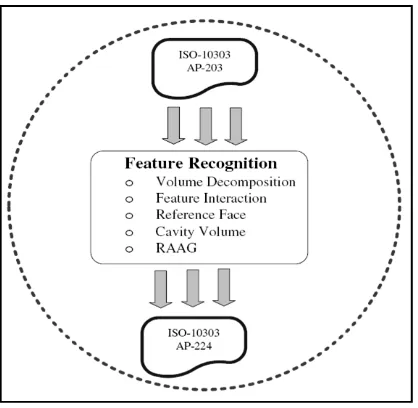
Based on figure 7, the first challenge in STEP-based manufacturing system is established a concurrent engineering environment across all manufacturing activities. A key element in this environment is feature which allows integration between CAD (as in AP203) and (as in AP224 and 238) data. However, recognizing AP224 features from an AP203 model is still being under development (Zhao, et al., 2009).
4 Project Framework
The proposed project framework is shown in figure 8, which consists of several important steps. Start from various kinds of 3-D geometric model design which is created in Autodesk Inventor, they are converted to STEP neutral data format, ISO 10303 AP203. AP203 is in a text file format and it is geometrical and topological rich data format, such as vertices, lines and surfaces is shown in figure 9. Then, these types of data will be extracted to a format which is useful for manufacturing feature extraction and recognition modules through a STEP feature-based system. Raw stock determination and subtraction of model from stock are the two important steps before implementing the manufacturing feature extraction and recognition process. Graph-based and rule-based approaches are proposed as the main automatic manufacturing feature recognition methods. Lastly, the recognized manufacturing features will be generated in ISO 10303 AP224 in text file, which is useful for
subsequent manufacturing processes. Figure 10 shows the expected result and steps in developing feature-based system for automated machining feature recognition of ISO 10303 AP 224 for prismatic components. The proposed algorithm for manufacturing feature extraction and recognition modules will be implemented by using Microsoft Office Access Database and running on Microsoft Window system.
5 Initial Result
This project is still under development and some of the initial result can be referred in figure 11 until figure 18 in appendix. Figure 11 shows the geometric model of a designed object from Autodesk Inventor. The
designed object which is in geometry and topological rich data format was converted to STEP neutral data format, ISO 10303 AP203 as shown in figure 9. Then, this data will be extracted and categorized into a format which is more useful in subsequent manufacturing feature recognition process by using all the append queries, update queries and select
397 | C i E T V E T 2 0 1 2
the queries have been used to extract the geometry and topological data are select query, union query, append query and also update query. At this stage, all of the important geometry and topological data have been extracted and categorized in close_shell table, advanced_face table, oriented_edge table, edge_curve table, face_bound table, edge_curve table, edge_loop table, plane table, vector table, vertex table,
cartesian_point table, direction table and axis2_placement table. These geometry and topological data are important for manufacturing feature recognition process. Before any manufacturing feature will be recognized, there is a convexity test will be implemented on the geometry and
topological data. This convexity test will determine the types of every edge in this data, whether it is convex or concave. This pattern of convexity of the edges will be become an important data in mapping the
manufacturing feature known as graph based approach and helping in manufacturing feature recognition with rule based feature recognition approach. Lastly, the manufacturing recognized features will be
converted to AP224 format data which is useful for CAPP and subsequent manufacturing process CAM. As a result, AP224 format data will close the gap between CAD and CAPP.
6 Summary
398 | C i E T V E T 2 0 1 2
References
Kramer, T., & Xu, X. (2009). STEP in a Nutshell
Advanced Design and Manufacturing Based on STEP. In X. Xu & A. Y. C. Nee (Eds.), (pp. 1-22): Springer London.
Shah, J. J., & Mantyla, M. (1995). Parametric and Feature Based
CAD/Cam: Concepts, Techniques, and Applications: John Wiley \\& Sons, Inc.
Xu, X. (2009). Integrating Advanced Computer-Aided Design,
Manufacturing, and Numerical Control: Principles and Implementations: Information Science Reference - Imprint of: IGI Publishing.
399 | C i E T V E T 2 0 1 2
Appendix
Table 1: Classification of feature recognition system (Shah & Mantyla, 1995)
Product Type Applications Shape Sheet metal features Design Prismatic Composite panel
feature Finite Element Analysis Rotational Machined features Process Planning Flat
Injection molding features
Inspection Uniform Cross section
Figure 1. Classification Of feature creation methods (Shah & Mantyla, 1995) AD-HOC INTERACTIVE DEFINITION RESTRICTED MACHINING REGION RECOGNITION SECTIONING CONVEX HULL DECOMPOSITION CELL DECOMPOSITON AUTOMATIC
RECOGNITION SYNTACTIC
RULE BASED BOUNDARY BASED PRE-DEFINED FEATURE RECOGNITION GRAPH-BASED FEATURE DEFINITION
METHODS NEURAL NET BASED
BOUNDARY MATCHING VOLUME
BASED DOF
[image:9.595.65.504.136.578.2]400 | C i E T V E T 2 0 1 2 FEATURE MODEL Shape Definition Dimension Attributes Feature Position Geometric Constraints Non-geom. Attributes GEOMETRIC MODEL Topological Entities Topological Graph Geometric Entities Topo-Geom. Pointers
[image:10.595.76.477.233.324.2]Figure 2. Relationship between feature and geometry (Shah & Mantyla, 1995)
[image:10.595.58.540.384.490.2]Figure 3. Interactive feature definition (FfG) (Shah & Mantyla, 1995)
Figure 4. Automatic feature recognition (FfG) (Shah & Mantyla, 1995)
Figure 5. Design by features (GIF) (Shah & Mantyla, 1995) GEOMETRIC
MODELLER GEOMETRIC MODEL
INTERACTIVE GRAPHICS
SYSTEM
FEATURE MODEL
USER1 USER2
GEOMETRIC MODELER GEOMETRIC MODEL FEATURE RECOGNITION ALGORITHM FEATURE EXTRACTION ALGORITHM FEATURE MODEL PRE-DEFINED FEATURES FEATURE MODELER GEOMETRIC
MODELER GEOMETRIC
MODEL
FEATURE MODEL
[image:10.595.123.477.563.701.2]401 | C i E T V E T 2 0 1 2
Figure 6. An integrated STEP-compliant manufacturing system (Zhao, et al., 2009)
[image:11.595.203.412.409.613.2]402 | C i E T V E T 2 0 1 2
Figure 8. Proposed project framework
#243=ADVANCED_FACE('',(#242),#208,.T.);
#244=CARTESIAN_POINT('',(-8.881784E-015,30.0,0.0)); #245=DIRECTION('',(0.0,1.0,0.0));
#246=DIRECTION('',(0.0,0.0,1.0));
#247=AXIS2_PLACEMENT_3D('',#244,#245,#246); #248=PLANE('',#247);
#249=CARTESIAN_POINT('',(49.999999999999993,30.0,20.0)); #250=VERTEX_POINT('',#249);
#251=CARTESIAN_POINT('',(-7.105427E-015,30.0,20.0)); #252=DIRECTION('',(1.0,0.0,0.0));
#253=VECTOR('',#252,50.0); #254=LINE('',#251,#253);
#255=EDGE_CURVE('',#212,#250,#254,.T.); #256=ORIENTED_EDGE('',*,*,#255,.T.);
#257=CARTESIAN_POINT('',(49.999999999999993,30.0,0.0)); #258=VERTEX_POINT('',#257);
#259=CARTESIAN_POINT('',(49.999999999999993,30.0,0.0)); #260=DIRECTION('',(0.0,0.0,1.0));
#261=VECTOR('',#260,20.0); #262=LINE('',#259,#261);
#263=EDGE_CURVE('',#258,#250,#262,.T.); #264=ORIENTED_EDGE('',*,*,#263,.F.);
#265=CARTESIAN_POINT('',(49.999999999999993,30.0,0.0)); #266=DIRECTION('',(-1.0,0.0,0.0));
#267=VECTOR('',#266,50.0); #268=LINE('',#265,#267);
404 | C i E T V E T 2 0 1 2
#320=VECTOR('',#319,50.0); #321=LINE('',#318,#320);
#322=EDGE_CURVE('',#228,#289,#321,.T.); #323=ORIENTED_EDGE('',*,*,#322,.T.); #324=ORIENTED_EDGE('',*,*,#294,.T.);
#325=EDGE_LOOP('',(#316,#317,#323,#324)); #326=FACE_OUTER_BOUND('',#325,.T.); #327=ADVANCED_FACE('',(#326),#310,.T.); #328=CARTESIAN_POINT('',(25.0,15.0,0.0)); #329=DIRECTION('',(0.0,0.0,1.0));
#330=DIRECTION('',(1.0,0.0,0.0));
#331=AXIS2_PLACEMENT_3D('',#328,#329,#330); #332=PLANE('',#331);
[image:14.595.90.467.364.632.2]#333=ORIENTED_EDGE('',*,*,#322,.F.); #334=ORIENTED_EDGE('',*,*,#233,.F.); #335=ORIENTED_EDGE('',*,*,#269,.F.);
Figure 9. Example of ISO 10303 AP203 in text file
405 | C i E T V E T 2 0 1 2
Figure 11. Geometric model designed by using Autodesk Inventor
[image:15.595.90.563.355.612.2]406 | C i E T V E T 2 0 1 2
Figure 13. Design view of Append Queries
[image:16.595.91.563.381.640.2]407 | C i E T V E T 2 0 1 2
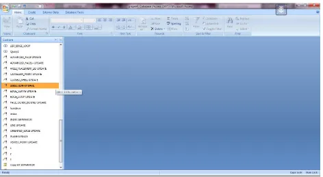
Figure 15. Design view of Update Queries
[image:17.595.94.562.377.628.2]408 | C i E T V E T 2 0 1 2
Figure 17. Edge_Loop table
[image:18.595.92.562.401.649.2]