Performance Analysis of Three-Phase
Four-Leg Voltage Source Converter
Z.Harish, Y.Suri babu
Abstract: A three-phase four-leg voltage
source converter with a new control scheme is discussed. The modulation method implemented comprises of calculation of offset voltage and then comparison with a carrier wave. The control of four-leg inverter through a new carrier based PWM and the impact of zero sequence voltage on neutral current is verified using simulation and the corresponding results are given.
Index Terms: Three-phase Four-leg converter, PWM, 3-D SVPWM, zero sequence voltage, neutral current.
1. INTRODUCTION
The use of non-linear loads is increasing gradually which leads to considerable increase in problems associated with them related to both consumer side and distributor side. Three-phase Four-wire service is commonly being used for many residential and commercial purposes. The single phase service is provided to those customers in such a manner to balance the load on each of the three phases. However the phase to neutral loads are not completely balanced. This unbalance may leads to flow of current in the neutral wire. The non-linear loads draw distorted currents which may contain third harmonic component in addition to fundamental component. As a result the harmonic currents are present not only on the phase conductors but also present in the neutral wire. This is due to flow of zero sequence component current due to asymmetry.
Z.Harish, M.Tech Student, Department of Electrical and
Electronics Engineering, RVR & JC CE, Guntur, INDIA.
Mr. Y.Suri Babu, Assistant Professor, Department of Electrical
and Electronics Engineering, RVR & JC CE, Guntur, INDIA.
The corresponding equation for the current in neutral wire is given by
In = - 3*Ia0
This leads to overloading of neutral wire and distribution transformer which may leads to fire hazard. The over sizing of neutral wire is an expensive solution and hence not economical. The harmonics in three-phase four wire systems can be filtered by use of three single-phase active or passive filters. These filters are to be connected between the individual phases and neutral wire. The use of passive filters is a simple approach for filtering but they have several disadvantages like over-size, more cost, more sensitive to temperature and aging. Another way of filtering is use of active filters. Three single phase active filters are needed for this purpose which involve use of twelve controlled switches. Though it is an effective method for filtering, a single unit instead of three separate units become more economical and easy maintenance.
One such method of implementing a single unit instead of three single phase units is a Four-Leg Voltage Source converter. This converter requires just eight controlled switches. The control strategy is shown below:
2. PROPOSED TOPOLOGY
An unbalance in load or source causes zero sequence voltage and current in three-phase, four-wire systems. Any topology providing neutral connection is required to control the zero sequence voltage. One such topology is three-phase, four-leg voltage source converter. A three-phase four-leg voltage source converter is a conventional three-phase converter with an additional leg i.e., fourth leg. The fourth leg also called as neutral leg is able to provide zero sequence voltage, so as to handle the neutral current caused by unbalanced load or source. The proposed topology is shown in Fig. 1
Fig. 1. Three-phase Four-Leg converter
The proposed four-leg converter is supplied by a constant dc voltage source Vdc and consists of total
8 controlled switches. IGBT‟s with internal diodes are used as controlled switches. The converter is connected through a three-phase impedance denoted by Z. The neutral point of the load is connected to middle point of the fourth leg denoted by „f‟. It can produce three independent phase to neutral voltages with an additional leg which are denoted as Vaf, Vbf and Vcf. The constraint for
these phase output voltages is given by the following inequality:
-Vdc ≤ Vaf , Vbf , Vcf ≤ Vdc
The respective pole voltages are given by Van, Vbn,
Vcn and offset voltage is denoted as Vfn. These pole
voltages and offset voltage have the following constraint:
-Vdc/2 ≤ Van , Vbn , Vcn ≤ Vdc/2
-Vdc/2 ≤ Vfn ≤ Vdc/2 (1)
The phase to neutral output voltages can be written in terms of respective pole voltages and common offset voltage as shown below:
Vaf = Van - Vfn
Vbf = Vbn - Vfn
Vcf = Vcn - Vfn
3. CONTROL SCHEME
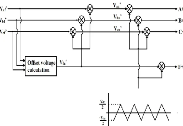
The proposed control scheme is a triangular carrier based Pulse Width Modulation (PWM) method. This scheme comprises of calculation of offset voltage from the three-phase reference voltages and comparing the pole-voltages with triangular carrier wave to obtain the switching signals. The proposed carrier based PWM method is shown below:
Fig. 2. PWM scheme for four-leg converter The three-phase reference voltages are given by Vaf*, Vbf*, Vcf*. Offset voltage Vfn* is calculated
from the reference voltages by a special procedure shown in the subsequent section 3.1. From the offset voltage, the respective pole voltages are calculated as shown:
Van* = Vaf* + Vfn*
Vbn* = Vbf* + Vfn*
Vcn* = Vcf* + Vfn* (2)
The obtained pole voltages are compared with the reference triangular carrier wave as shown in Fig. 2 to get the pulses for the upper switches of the four-leg converter (i.e., A+, B+, C+, F+). The complement of respective switching signals are the control signals for lower switches of the converter. The proposed carrier based PWM method when compared with conventional Sinusoidal PWM method has the following advantages:
i. Lower harmonic currents ii. Higher modulation index
The proposed method is equivalent to 3-D SVPWM method but its implementation is simpler. The 3-D SVPWM method of three-phase, four leg system requires some complicated procedures such as adjacent voltage vectors selection, duty-ratio calculation, on-time calculation of each switch etc., hence, its implementation requires both digital logic and computational power and leads to burden on recent Digital Signal Processor (DSP) systems.
3.1 OFFSET VOLTAGE CALCULATION
Vaf*, Vbf*, Vcf* are the three reference phase
voltages required for offset voltage calculation. From these three reference voltages, functions Vmin,
Vmid, Vmax are written as shown below:
Vmin = min (Vaf*, Vbf*, Vcf*),
Vmid = mid (Vaf*, Vbf*, Vcf*),
Vmax = max (Vaf*, Vbf*, Vcf*). (3)
Where,
Vmin calculates the minimum value among Vaf*,
Vbf*, Vcf*.
Vmid calculates the medium value among Vaf*, Vbf*,
Vcf*.
Vmax calculates the maximum value among Vaf*,
Vbf*, Vcf*
The difference between minimum and maximum value of phase to neutral voltages is limited by the following constraint:
Vmax – Vmin ≤ Vdc (4)
The offset voltage Vfn* is selected as shown below
to get the optimum switching sequence similar to symmetrically aligned-class I 3-D SVPWM: Vfn* = - Vmax/2, Vmin>0
= - Vmin/2, Vmax>0
= - (Vmax+Vmin)/2, Otherwise
By combining, the above equation can be rewritten as:
Vfn* = mid [- Vmax/2, - Vmin/2, - (Vmax+Vmin)/2] (5)
From the offset voltage, the respective pole voltages can be calculated from equation (2).
Hence the ON-times of the upper switches of four-leg converter are obtained as
Ta = Ts/2 + (Van*/Vdc)*Ts
Tb = Ts/2 + (Vbn*/Vdc)*Ts
Tc = Ts/2 + (Vcn*/Vdc)*Ts
Tf = Ts/2 + (Vfn*/Vdc)*Ts (6)
Where, Ta, Tb, Tc, Tf are the ON-times of upper
switches of legs connecting a, b, c and f phases respectively and Ts is the switching frequency.
The equations (3), (5) and (6) are implemented as shown in Fig. 2. This method produces optimum switching sequence similar to symmetrically aligned-class I 3-D SVPWM but in a simplified manner.
Calculation of maximum magnitudes of
balanced three-phase voltage and zero sequence voltage:
The balanced three-phase voltages along with zero sequence voltage can be expressed as
Vaf = Amax * cos(ωt) + V0(t)
Vbf = Amax * cos(ωt - 2π/3) + V0(t)
Vcf = Amax * cos(ωt + 2π/3) + V0(t) (7)
Where, V0(t) is the zero sequence voltage and it
can be zero, a constant or an arbitrary function of time.
The value of maximum magnitude i.e., Amax of
balanced voltage can be obtained from the constraint given by (4) as
Amax = Vdc/√3 (8)
To calculate the maximum magnitude of zero sequence voltage, first we should calculate the maximum magnitude of offset voltage, Vfn0 with no
zero sequence voltage. Hence with no zero sequence voltage equation (7) becomes
Vaf = Amax * cos(ωt)
Vbf = Amax * cos(ωt - 2π/3)
The offset voltage Vfn0 calculated from equation (9)
satisfies
- Amax/4 ≤ Vfn0 ≤ Amax/4 (10)
Using equation (8), equation (10) can be rewritten as
-Vdc/(4*√3) ≤ Vfn0 ≤ Vdc/(4*√3) (11)
The range available for zero sequence voltage is nothing but the difference between the total region of offset voltage given by (1) and the region of offset voltage with no zero sequence voltage given by (11) and hence satisfies
V0 ≤ Vdc/2 - Vdc/(4*√3) i.e.,
V0max = 0.3557* Vdc.
4. SIMULATION RESULTS
The proposed carrier based PWM method for four-leg converter shown in Fig. 1 has been implemented and analyzed through computer simulation. The three-phase load is composed of resistors and inductors. Various parameters used for simulation are summarized in the following table:
DC bus voltage (Vdc) 300 v
Carrier frequency 5 kHz
Resistance (R) 40Ω
Inductance (L) 50 mH
The four-leg converter is analyzed for three simulation conditions:
I. No zero sequence voltage II. Constant zero sequence voltage III. Time-varying zero sequence voltage The results consisting of voltage references, three-phase load currents and neutral current are shown for each of the three cases.
4.1 No zero sequence voltage
The three phase to neutral voltage references are given by following equation:
Vaf* = Amax * cos(ωt) Vbf* = Amax * cos(ωt - 2π/3) Vcf* = Amax * cos(ωt + 2π/3) Where, ω = 120*π Amax = Vdc /√3 = 173.2 V
With these reference voltages, the results are shown below:
(a)
(b)
(c)
Fig. 3. Simulation results for section 4.1: (a) voltage references, (b) three-phase load currents and (c) neutral current
0 0.01 0.02 0.03 0.04 0.05 0.06 0.07 0.08 0.09 0.1 -300 -200 -100 0 100 200 300 Time(sec) V o lt a g e R e fe re n c e s (v o lt s )
zero line Vaf* Van* Vfn*
0 0.01 0.02 0.03 0.04 0.05 0.06 0.07 0.08 0.09 0.1 -10 -5 0 5 10 Time(sec) C u rr e n t( A m p )
zero line Iaf Ibf Icf
0 0.01 0.02 0.03 0.04 0.05 0.06 0.07 0.08 0.09 0.1 -10 -5 0 5 10 Time(sec) N e u tr a l c u rr e n t( A m p ) zero line In
With no zero sequence voltage the three phase load currents are balanced and neutral current is zero.
4.2 Constant zero sequence voltage
The three phase to neutral voltages along with constant zero sequence voltage are given by Vaf* = Amax * cos(ωt) + V0max
Vbf* = Amax * cos(ωt - 2π/3) + V0max
Vcf* = Amax * cos(ωt + 2π/3) + V0max
Where, ω = 120*π Amax = Vdc /√3
= 173.2 V
V0max = Vdc/2 - Vdc/(4*√3)
= 106.7 V
With these reference voltages, the results are shown below:
(a)
(b)
(c)
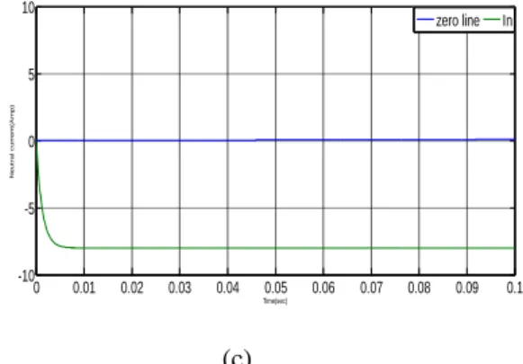
Fig. 4. Simulation results for section 4.2: (a) voltage references, (b) three-phase load currents and (c) neutral current
With constant zero sequence voltage there is a shift in three phase load currents and neutral current is of fixed value.
4.3 Time-varying zero sequence voltage
The three phase to neutral voltages along with zero sequence voltage are given by
Vaf* = Amax * cos(ωt) + V0max * cos(ωt)
Vbf* = Amax * cos(ωt - 2π/3) + V0max * cos(ωt)
Vcf* = Amax * cos(ωt + 2π/3) + V0max * cos(ωt)
Where, ω = 120*π Amax = Vdc /√3
= 173.2 V
V0max = Vdc/2 - Vdc/(4*√3)
= 106.7 V
With these reference voltages, the results are shown below: (a) 0 0.01 0.02 0.03 0.04 0.05 0.06 0.07 0.08 0.09 0.1 -300 -200 -100 0 100 200 300 Time(sec) V o lt a g e r e fe re n c e s (V o lt s )
zero line Vaf* Van* Vfn*
0 0.01 0.02 0.03 0.04 0.05 0.06 0.07 0.08 0.09 0.1 -10 -5 0 5 10 Time(sec) C u rr e n t( A m p )
zero line Iaf Ibf Icf
0 0.01 0.02 0.03 0.04 0.05 0.06 0.07 0.08 0.09 0.1 -10 -5 0 5 10 Time(sec) N e u tr a l c u rr e n t( A m p ) zero line In 0 0.01 0.02 0.03 0.04 0.05 0.06 0.07 0.08 0.09 0.1 -300 -200 -100 0 100 200 300 Time(sec) V o lt a g e R e fe re n c e s (V o lt s ) zero line Vaf* Van* Vfn*
(b)
(c)
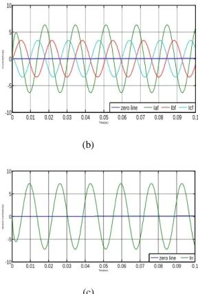
Fig. 5. Simulation results for section 4.3: (a) voltage references, (b) three-phase load currents and (c) neutral current
With time-varying zero sequence voltage there is an unbalance in three phase load currents and time-varying neutral current.
5 CONCLUSION
A three-phase, four-leg converter is proposed with a new modulation technique. The converter is controlled through carrier based PWM technique by using an offset voltage concept. The feasibility of the converter in providing the zero sequence voltage to handle the neutral current is verified through computer simulation. It is observed from the simulation results, that the flow of current in the neutral wire does depends upon the zero sequence voltage and vary according to the value of zero sequence voltage. This method is equivalent to symmetrically aligned-class I 3-D SVPWM but with easy implementation. Under light, heavy, balanced and unbalanced load or source conditions, it observed that the proposed method is having more commutation frequency and thus more switching losses. Hence use of Predictive Voltage
Control scheme may be adopted in future to improve the performance of Four-leg converter.
REFERENCES
[1] C. A. Quinn and N. Mohan, “Active filtering of harmonic currents in three-phase, four-wire systems with three-phase and single-phase non-linear loads,” in Proc. IEEE-APEC’93 Conf., 1993, pp. 841-846.
[2] R. Zhang, V.H. Prasad, D. Boroyevich and F. C. Lee, “Three-dimensional space vector modulation for four-leg voltage-source converters,” IEEE Trans. Power Electron., vol. 17, pp. 314-325, May 2002.
[3] S. M. Ali and M. P. Kazmierkowski, “PWM voltage and current control of four-leg VSI,” in
Proc. IEEE ISIE’98 Conf., 1998, pp. 196-201.
[4] A. Campos, G.. Joos, P. D. Ziogas, and J. F. Lindsay, “Analysis and design of a series voltage unbalance compensator based on a three-phase VSI operating with unbalanced switching functions,” IEEE Trans. Power
Electron., vol. 10, pp. 269-274, May 1994.
[5] V. H. Prasad, D. Boroyevich, and R. Zhang, “Analysis and comparison of space vector modulation schemes for a four-leg inverter,” in
Proc. IEEE-APEC’97 Conf., 1997, pp.864-871.
0 0.01 0.02 0.03 0.04 0.05 0.06 0.07 0.08 0.09 0.1 -10 -5 0 5 10 Time(sec) C u rr e n t( A m p )
zero line Iaf Ibf Icf
0 0.01 0.02 0.03 0.04 0.05 0.06 0.07 0.08 0.09 0.1 -10 -5 0 5 10 Time(sec) N e u tr a l C u rr e n t( A m p ) zero line In