Study on Effect of Slot on Performance of Circular
Pin Fin
Vikas Bansal1, Bhushan Kumar2 Peeyush Chauhan3
1
PG Scholar, Department of Mechanical Engineering, Devbhoomi Institute of Technology, Dehradun.
2
Assistant Professor, Department of Mechanical Engineering, Devbhoomi Institute of Technology, Dehradun.
3
Assistant Professor, Department of Mechanical Engineering, Shri Ram Group of Colleges, Muzaffarnagar.
Abstract: In this paper an effort is made for theoretical and computational analysis of circular pin fin made of copper and aluminium. In past years also various efforts has been made by researchers to improve the heat transfer rate through the fin. In the present work effect of slot in the cross section of the circular pin fin along its length on its performance has been observed. For this first theoretical and then computational analysis has been done by using the software SolidWorks 2012. It has been observed from the study that the introduction of slot improves heat transfer rate through the fin and reduces the cost of pin fin array for same heat transfer rate.
Keywords: Pin Fin Array, Slot, Heat Transfer, Temperature Distribution, Solid Works.
I. INTRODUCTION
Pin fins are used in the form of array. There are various type of cross section like circular, rectangular, elliptical pin fins used in a heat sink. The concept of heat sinks arises from increasing the heat transfer area to reach maximum heat transfer rate of heat losses in a limited space. Circular pin fins are used in gas turbine blade cooling and to remove heat from various electronic components like transistors.
II. RELATED WORK
Khan Waqar Ahmed [1] studied the heat transfer coefficient for the heat sink and the average temperature of the fluid by an energy balance and optimize overall performance of fin geometry for combined effect of thermal resistance and Pressure drop also studied various parameters on pin fin array.
Dewan A. et al. [2] presents a computational study of the steady –state thermal and air flow resistance characteristics and performance analysis through a rectangular channel with circular pin fins attached to a flat surface. He concluded that Reynolds number from 550 to 685 is the best range for operating a compact heat exchanger and if we consider different factors like heat transfer, density and pressure drop for compact heat exchanger then aluminum is the best fin material.
Didwania Mukesh et al. [3] present the results of study and analysis of heat transfer rate and loss of pressure for various types shapes fins with a rectangular duct by keeping the same surface area in each case. For analysis he used CFD tool ANSYS 12.0 fluent. He concluded that in Laminar flow heat transfer rate is maximum for circular fin and it has a minimum value for rectangular fin while loss of pressure is minimum in case of circular fin and maximum in case of rectangular fin.
Tomar Yatendra Singh & Sahu M.M. [4] completed experimental and computational study of performance of pin fin under forced convection heat transfer. They compared the results obtained from both methods and concluded that when transverse pitch of circular pin fin increases then thermal resistance decreases. At the same time roughness factor of fin surface also shows considerable deviation in results.
Singh Pradeep et al. [5] completed a study on design and analysis for heat transfer through fin with extensions and concluded that by using rectangular extensions on fins heat transfer through fin increases near about a range of 5% to 13%.
Samarth Ashish B. & Sawankar Kapil S. [6] experimentally studied the thermal performance of perforated pin fin arrays in staggered arrangement. They concluded that height of the pin fin is the most effective parameter for friction factor. They obtained optimum value of fin height, Reynold number and pitch for maximum heat transfer. They also concluded that perforated fin gives better performance than solid cylindrical fin.
Oswal ShrenikKumar et al. [8] studied the effect of various factors like arrangement of pin fin array, cross section of fin, number of fin, material of pin fin, by-pass factor, location of fan, nature of fluid flow, surface finish of fins & inclination of fins on the performance of pin fin array and concluded some important results to improve heat transfer through pin fin array,
Kansal Santosh & Laad Piyush [9] emphasis on a computational comparative study of heat sink having fins of various profiles namely rectangle, Trapezoidal, Interrupted Rectangle, Square, Circular Inclined and Circular Staggered. On the basis of study they concluded that circular pin fins give better performance for optimum cooling.
Reddy Y. Pratapa et al. [10] studied the temperature distribution analysis of a composite pin fin by experimentally and using a FEM software ANSYS. They concluded that composite pin fin shows less rate of heat transfer as compare to solid cylindrical pin fin. Shaikh Farhat & Challa Jayaramulu [11] performed a CFD analysis on a circular pin fin array by using ANSYS 16.2 and studies various parameters to improve the cooling performance of pin fin array.
Singh Balendra & Satish Singh [12] compared the performance of a notched & un-notched fin by experimental and simulation method. They concluded that a notched fin gives better performance as compare to an un-notched fin.
Reddy R. Sudheer Kumar et al. [13] studied the effect of perforation on the performance of pin fin by using a simulation software ANSYS and observed that temperature drop and heat transfer rate is more along the perforated fin as compare to non-perforated fin..
III.THEORETICAL AND COMPUTATIONAL ANALYSIS
For the analysis we consider a general problem of a cooling of electronic device from a reference book of Heat and Mass Transfer
[14].
Problem-: Circular pin fins are used to dissipate heat from an electronic device. The length of the fin is 2.5 cm and its diameter is 0.25cm. In first case fin is made of copper and its conductivity is 390W/m-K and in second case fin is made of aluminum and its
conductivity is 230W/m-K. In both case the convection coefficient around the circumference of the fin is 30W/m2K. The base of the
fin is at a temperature of 95 0C & the surrounding air temperature is 250C. Assume pin fins are insulated at the tip. Compare
temperature distribution in the fin, Heat loss through the fin, efficiency of the fin, effectiveness of the fin.
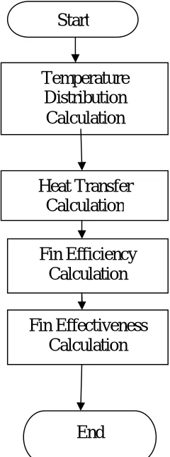
[image:2.612.263.383.395.717.2]A. Procedure for Theoretical Analysi
Fig. 1 A Flow Chart showing Process for theoretical analysis of circular fin.
Temperature
Distribution
Calculation
Heat Transfer
Calculation
Fin Efficiency
Calculation
Fin Effectiveness
Calculation
B. Theoretical Temperature Distribution Case-I: For Copper fin
TABLE. 1 Theoretical temperature distribution for copper fin. Distance from root of fin (x
in cm)
Without slot (in 0K) With one slot (in 0K) With two slot (in 0K)
0.5 367.071 366.55 365.73
1.0 366.351 365.44 363.98
1.5 365.838 364.65 362.74
2.0 365.532 364.18 361.99
2.5 365.429 364.02 361.75
[image:3.612.87.521.254.350.2]
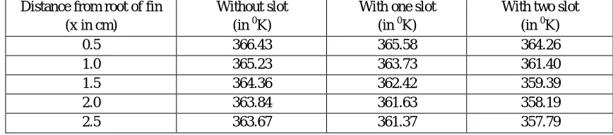
Case-II: For Aluminium Fin
TABLE. 2 Theoretical temperature distribution for aluminium fin. Distance from root of fin
(x in cm)
Without slot (in 0K)
With one slot (in 0K)
With two slot (in 0K)
0.5 366.43 365.58 364.26
1.0 365.23 363.73 361.40
1.5 364.36 362.42 359.39
2.0 363.84 361.63 358.19
2.5 363.67 361.37 357.79
C. Procedure for Computational Analysis
Fig.2 A Flow Chart showing Process for theoretical analysis of circular fin.
Start
Modelling of Fin
Split the
fin model
Sketching
and Extrude
Simulation of Fin Model
Assign Material to Fin Model
Apply Thermal Load and
Boundary Conditions
Generate Mesh and
Run it.
Result
[image:3.612.152.474.378.715.2]D. Computational Temperature Distribution Case-I: For Copper fin
TABLE. 3 Computational temperature distribution for copper fin. Distance from root of fin (x
in cm)
Without slot (in 0K) With one slot (in 0K) With two slot (in 0K)
0.5 367.197 366.707 365.956
1.0 366.451 365.587 364.261
1.5 365.884 364.784 363.052
2.0 365.538 364.294 362.32
2.5 365.414 364.114 362.061
[image:4.612.84.521.249.517.2]
Case-II: For Aluminium Fin
TABLE. 4 Computational temperature distribution for aluminium fin. Distance from root of fin
(x in cm)
Without slot (in 0K)
With one slot (in 0K)
With two slot (in 0K)
0.5 366.781 365.772 364.585
1.0 365.492 363.935 361.85
1.5 364.502 362.622 359.908
2.0 363.9 361.822 358.738
[image:4.612.122.502.529.711.2]2.5 363.613 361.528 358.323
Fig.3 Computational temperature distribution result for copper fin without slot.
Fig.5 Computational temperature distribution result for copper fin with two slot.
Fig.6 Computational temperature distribution result for aluminium fin without slot.
Fig.8 Computational temperature distribution result for aluminium fin with two slot.
IV.RESULTS AND DISCUSSION
Results for various parameters like temperature distribution, heat transfer, efficiency and effectiveness are obtained from theoretical and computational analysis. Effect of slot on fin performance has been discussed below-:
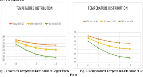
A. Effect of slot on Temperature Distribution Case-I: For Copper Fin
Fig. 9 Theoretical Temperature Distribution of Copper Fin in Fig. 10 Computational Temperature Distribution of Copper Fin in
various Cases. various Cases.
[image:6.612.51.549.389.659.2]Case-I: For Aluminium Fin
[image:7.612.50.562.87.295.2]
Fig. 11 Theoretical Temperature Distribution of Aluminium Fin Fig. 12 Computational Temperature Distribution of Aluminium Fin
in various Cases. in various Cases.
It is clear from temperature distribution graphs obtained from both theoretical and computational analysis that temperature
distribution is more uniform in case of fin without any slot as compare to fin with slot. As number of slot increases the uniformity in temperature distribution decreases.
[image:7.612.55.555.390.534.2]B. Effect of slot on Heat Transfer through Fin Case-I: For Copper Fin
TABLE.5 Heat Transfer through Copper Fin in Various Cases
Fig. 13 Heat Transfer through Copper Fin in Various
Cases
[image:7.612.325.552.631.710.2]From graph it is clear that by making slot there is an increase in heat transfer through the fin. Due to one slot heat transfer increases by 23% and due to two slots heat transfer increases by 45.36% as compare to heat transfer through the fin without any slot. Case-II: For Aluminium Fin
TABLE.6 Heat Transfer through Copper Fin in Various Cases
Fig. 14 Heat Transfer through Aluminium Fin in
Case Qfin (in Watts)
Without slot 0.4021
With one slot 0.4975
With two slot 0.5845
Case Qfin (in Watts)
Without slot 0.3954
With one slot 0.4845
From graph it is clear that by making slot there is an increase in heat transfer through the fin.Due to one slot heat transfer increases by 22.86% and due to two slots heat transfer increases by 42% as compare to heat transfer through the fin without any slot.
C. Effect of slot on Efficiency of Fin
[image:8.612.45.566.134.274.2]Case-I: For Copper Fin
TABLE.7 Efficiency of Copper Fin in Various Cases
Case Efficiency of Fin ηfin (%)
Without slot 97.5
With one slot 96.17
With two slot 93.92
Fig. 15 Efficiency of Copper Fin in Various Cases
From graph it is clear that by making slot there is a decrease in efficiency of the copper fin. Due to one slot efficiency decreases by 1.33% while due to two slots it decreases by 3.58% as compare to efficiency of fin without slot.
[image:8.612.333.565.345.462.2]Case-I: For Aluminium Fin
TABLE.8 Efficiency of Aluminium Fin in Various Cases
Case Efficiency of Fin ηfin (%)
Without slot 95.89
With one slot 93.65
With two slot 90.24
Fig. 16 Efficiency of aluminium Fin in Various Cases
From graph it is clear that by making slot there is a decrease in efficiency of the fin. Due to one slot efficiency decreases by 2.24% while due to two slots it decreases by 5.65% as compare to efficiency of fin without slot.
D. Effect of slot on Effectiveness of Fin
[image:8.612.44.564.346.465.2]Case-I: For Copper Fin
TABLE.9 Effectiveness of Copper Fin in various cases
Case Effectiveness of fin εfin
Without slot 39.04
With one slot 60.61
With two slot 95.69
Fig. 17 Effectiveness of Copper Fin in Various Cases
From graph it is clear that by making slot there is an increase in effectiveness of the fin.Due to one slot effectiveness increases by
[image:8.612.331.565.556.676.2]Case-II: For Aluminium Fin
TABLE.10 Effectiveness of Copper Fin in various cases
Case Effectiveness of fin εfin
Without slot 20.23
With one slot 59.03
With two slot 91.94
Fig. 18 Effectiveness of aluminium Fin in Various Cases
From graph it is clear that by making slot there is an increase in effectiveness of the fin.Due to one slot effectiveness increases by
2.93 times while due to two slots it increases by 4.54 times as compare to effectiveness of fin without slot
V. CONCLUSIONS
From the above study following conclusions can be made
A. A fin made of aluminum with one slot transfers more heat as compare to heat transferred by the fin made of copper without any
slot. Therefore we can use aluminum fin instead of copper fin in such case and can save the cost in the manufacturing of fin.
B. A fin with slotted cross section transfers a large amount of heat as compare to fin without slot.
C. As number of slot on fin increases, surface area of fin increases but volume of the fin decreases which results in lesser mass and
low material cost.
REFERENCES
[1] Khan. Waqar Ahmed, “Modelling of Fluid Flow and Heat Transfer for Optimization of Pin-Fin Heat Sinks”, A thesis for PhD (Waterloo University, Canada), 2004
[2] Dewan A., Patro P., Khan I. and Mahanta P., “The effect of fin spacing and material on the performance of a heat sink with circular pin fins”, Proc. ImechE Vol.224 Part A: J. Power and Energy2009
[3] Didwania Mukesh, Krishan Gopal and Ravikant, April 2013. “Study and analysis of heat transfer through two different shape fins using CFD tool”, International Journal of IT, Engineering and Applied Science Research (IJIEASR). Vol 2, No. 4. ISSN: 2319-4413
[4] Tomar Yatendra Singh and Sahu M.M., September 2013. “Comparative study of performance f pin fin under forced convection heat transfer”, International Journal of Research & Technology (IJERT). Vol 2, Issue 9. ISSN: 2278-0181
[5] Singh Pradeep, Lal Harvinder and Ubhi Baljit Singh, May 2014. “Design and analysis for heat transfer through fin with extensions”, International Journal of Innovative Research in Science, Engineering and Technology (IJIRSET). Vol. 3, Issue 5, ISSN: 2319-8753
[6] Samarth Ashish B. and Sawankar Kapil S., July 2014. “Thermal performance of perforated pin-fin array in staggered arrangement”, International Journal of Scientific & Engineering Research (IJSER). Vol. 5, Issue 7, ISSN: 2229-5518
[7] Jaideep Pandit, Megan Thompson, Srinath V Ekkad & Scott T. Huxtable, 2014. “Effect of pin fin to channel height ratio and pin fin geometry on heat transfer performance for flow in rectangular channels”, International Journal of Heat &Mass Transfer, Elsevier, Vol.77, pp.359-368
[8] Oswal Shrenikkumar, Jagtap Hemant and Mane Ajit, June 2015. “Factors affecting on thermal Performance of Fins & Analysis of Fins with ANSYS Icepak”, International Journal of Innovative Research in Science, Engineering and Technology, Vol.4 Issue 6, ISSN: 2319-8753
[9] Kansal Santosh and Laad Piyush, June 2015. “Performance & thermal analysis of heat sink with fins of different configuration using CFD”, International Journal of Scientific & Engineering Research, Vol. 6, Issue 6, ISSN: 2229-5518
[10] Reddy Y. Pratapa, Kumar B.Jitendra, Srinivasulu D. and Dr. Rao Ch. Srinivasa, October, 2015. “Temperature distribution analysis of composite pin fin by experimental and finite element method”, International Journal of Innovative Research in Science, Engineering and Technology (IJIRSET). Vol. 4, Issue 10, ISSN: 2319-875
[11] Shaikh Farhat and Challa Jayaramulu, May, 2016. “CFD analysis of a circular pin fin”, International Journal of Scientific Engineering and Research (IJSER). Vol. 4, Issue 5, ISSN: 2347-387
[12] Singh Balendra and Singh Satish, September, 2016. “A research paper on heat transfer in notch fin and unnotch finInternational Journal for Research in Applied Science & Engineering Technology (IJRASET). Vol. 4, Issue 9, ISSN: 2321-9653
[13] Reddy R. Sudheer Kumar, Dr. Rajulu K. Govinda and Dr. Basha S.M. Jameel, May, 2017. “Thermal analysis of pin fin with different shape forms using ANSYS”, International Journal of Engineering Science and Computing. Vol.7, Issue 5, 2017