Optimization of Internal Combustion Engine Piston
Bapi Raju. V1, Phanindra.Y.B.S2
1
Assistant Professor, Department of Mechanical Engineering, V. R. Siddhartha Engineering College, Vijayawada-520 007, India
2
Student , Department of Mechanical Engineering, V. R. Siddhartha Engineering College, Vijayawada-520 007, India
Abstract: In this present work suitable material for design of I.C. engine piston is determined from Aluminium alloy and Aluminium composites. Also optimum dimensions of the Hero Karizma ZMR petrol engine piston are optimized from weight point view. For modelling and analysis CATIA V5R20 & ANSYS 14.5 softwares are used.
Keywords: FEM, Piston, Hero Karizma ZMR petrol engine, Aluminum alloys and composites.
I. INTRODUCTION
Engine pistons are one of the most complex components among all automotive and other industry field components. The engine can be called the heart of a vehicle and the piston may be considered the most important part of an engine. There are lots of research works proposing, for engine pistons, new geometries, materials and manufacturing techniques, and this evolution has undergone with a continuous improvement over the last decades and required thorough examination of the smallest details. Notwithstanding all these studies, there are a huge number of damaged pistons. Damage mechanisms have different origins and are mainly wear, temperature, and fatigue related. But more than wear and fatigue, damage of the piston is mainly due to stress development, namely- Thermal stress, Mechanical stress.
This paper describes the stress distribution on piston of internal combustion engine by using FEA. The main objectives are to determine the best material and optimum design using structural analysis. The paper describes the FEA technique to predict the higher stress and critical region on the component. Using CATIAV5 software the structural model of a piston was developed. Using ANSYS V14.5 software, simulation and stress analysis was performed.
II. OBJECTIVESOFPRESENTSTUDY
Finding the most suitable material for given stress conditions from the given list of materials generally used to make the pistons. Optimizing the dimensions of the piston for achieving the lowest weight.
III. METHODOLOGY
A. Design of piston using CATIA
B. Meshing of designed model using ANSYS 15.
C. Analysis of piston by stress analysis method.
D. Comparing the performance of aluminum alloy and aluminium composite under structural analysis process.
E. Optimization using RSM in order to decrease its weight(volume)
IV. ENGINESPECIFICATIONANDPROPERTIESOFMATERIALSUSED: The engine specifications used for this work is a four stroke single cylinder type Hero Karizma ZMR petrol engine.
Table 1 Specifications of the piston
PARAMETERS
VALUES
Engine type Four stroke ,petrol engine
Number of cylinders Single cylinder
Bore 65.5
Stroke 66.2
Maximum power 14.9KW @ 8000rpm
Maximum torque 19.7Nm @ 6500 rpm
Table 2: Properties of materials
S.NO PARAMETERS Aluminium alloy
Aluminium Composite (Al-SiC10%-TiB25%)
1. Density (kg/m3) 2684.95 2850.5
2. Poisson ratio 0.33 0.314
3. Coefficient of thermal expansion(1/C) 23×10-6 24×10-6
4. Elastic modulus(Gpa) 71 106.05
5. Yield strength(Mpa) 280 250
6. Ultimate tensile strength (Mpa) 310 285
7. Thermal conductivity(W/m/0C) 154 217.5
V. PREVIOUSSTUDY
Dilip kumar sonar , Madhura Chattopadhyay studied thed design of piston head[1].Tadala akhil et.al have analyzed piston headmade of Aluminum alloys[2].Sundaram.K , Palanikumar.N and Kethavath Vishaldid et.al similar analysis using composites[3,4]. H.C.Anilkumar et.al, B.S.Motgi, R Patil and Arun Kumar M. B. and R. P.Swamy investigated the mechanical properties of Aluminum alloys [5,6,7].Ch.Venkata Rajam et.al ,A.R. Bhagat, Y.M. Jibhakate have done studies on Optimization of I.C. Engine Piston [8,9]
VI. NOMENCLATURE IP = indicated power produced inside the cylinder (W)
N = engine speed (rpm) L = length of stroke (mm)
A = cross-section area of cylinder (mm2) mp = mass of the piston (Kg)
V = volume of the piston (mm3) tH = thickness of piston head (mm) D = cylinder bore (mm)
Pmax = maximum gas pressure or explosion pressure (Mpa)
σt = allowable tensile strength (Mpa) σut = ultimate tensile strength (Mpa)
K = thermal conductivity (W/m K)
Tc = temperature at the centre of the piston head (K) Te = temperature at the edge of the piston head (K)
HCV = Higher Calorific Value of fuel (KJ/Kg) = 48000 KJ/Kg BP = brake power of the engine per cylinder (KW)
C = ratio of heat absorbed by the piston to the total heat developed in the cylinder = 5% or 0.05 t1= radial thickness of ring (mm)
Pw = allowable radial pressure on cylinder wall (N/mm2) = 0.025 Mpa
σp = permissible tensile strength for ring material (N/mm2) = 110 N/mm2
t2 = axial thickness of piston ring (mm) b1 = width of top lands (mm)
t3 = thickness of piston barrel at the open end (mm) ls = length of skirt (mm)
do = outer diameter of piston pin (mm)
Mechanical efficiency of the engine (η) = 70 %. Η = Brake power (B.P)/ Indicating power
nr = the number of rings
VII. DESIGNDIMENSIONSOFPISTON
A. The parameters tH ,t1, t2, b1, b2, t3, are calculated using the following steps
1) Thickness of Piston Head (tH) :The piston thickness of piston head calculated using the following Grashoff’s formula, tH =√
(3pD2)/ (16σt) in mm
2) Radial Thickness of Ring (t1): 1 = × √3 /
3) Axial Thickness of Ring (t2): The axial thickness of the rings may be taken as t2 = 0.7t1 to t1 or 2 = /10 ×
4) Width of the top land (b1): The width of the top land varies from b1= tH to 1.2 t
5) Width of other lands (b2): Width of other ring lands varies from b2= 0.7t2 to t
6) Maximum Thickness of Barrel at the top end (t3): t3=0.03×D+t1+4.
7) Length of the skirt ls= (0.6D to 0.8
8) Piston pin diameter (do): d0= (0.28D to 0.38D)
9) I.P = B.P /η = 14.9/0.9 = 16.55 KW
Also, I.P = P x A x L x N /2 Substituting the values we have P = 13.56 Mpa
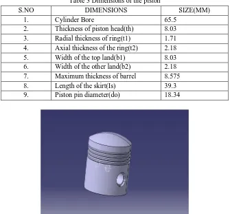
[image:3.612.139.474.409.720.2]The dimensions for the piston is calculated and are represented in the table given below. These are used for the modeling of piston in CATIA.In the above procedure the dimensions of the ribs are neglected, so as to make the design for the piston to be simple. The modelled piston is shown in figure 1.
Table 3 Dimensions of the piston
S.NO DIMENSIONS SIZE(MM)
1. Cylinder Bore 65.5
2. Thickness of piston head(th) 8.03
3. Radial thickness of ring(t1) 1.71
4. Axial thickness of the ring(t2) 2.18
5. Width of the top land(b1) 8.03
6. Width of the other land(b2) 2.18
7. Maximum thickness of barrel 8.575
8. Length of the skirt(Is) 39.3
VIII. ANSYSSTIMULATION
A. ALUMINUM ALLOY
[image:4.612.200.416.119.262.2]Deformation, stress and strain for Al alloy are as shown in figures 2,3,4 respectively
[image:4.612.192.421.292.426.2]Fig 2 Deformation of Al alloy piston
Fig 3 Stress of Al alloy piston
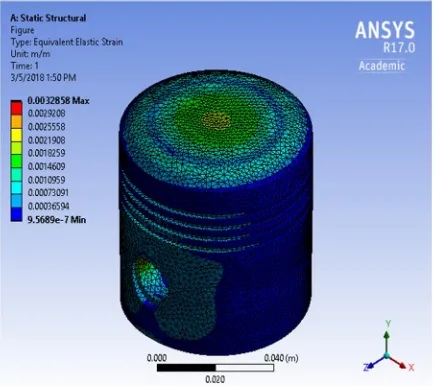
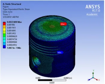
Fig 4 Elastic Strain of Al alloy piston
B. ALUMINUM COMPOSITES
[image:4.612.198.415.457.650.2]Fig 5 Deformation of Al-SiC10%-TiB25% composite
Fig 6 Stresses in Al-SiC10%-TiB25% composite
Fig 7 Elastic Strain in Al-SiC10%-TiB25% composite
As can be seen the composite is better than the alloy, because the deformation produced in aluminum composite is 40% less than the deformation produced in aluminum alloy. Although the stresses in composite are 5MPa more than that produced in alloy we can use composite for the design of piston.
IX. OPTIMIZATION
Optimization is done in order to achieve the objective of Minimization of the volume (weight) without crossing the stress and deflection limits. Following input parameters taken for optimization
[image:5.612.220.395.421.561.2]P6= width of the other land (b2)
[image:6.612.66.544.117.308.2]The Design of Experiments is used to find the optimum points the bounds of the input parameters are taken as follows.
Table 4 Lower and Upper limits of parameters
ID Name Classification Lower Bound Upper Bound
P1 XYPlane.L13 Continuous 7.227 [mm] 8.833 [mm]
P2 XYPlane.L14 Continuous 1.539 [mm] 1.881 [mm]
P3 XYPlane.L15 Continuous 1.962 [mm] 2.398 [mm]
P4 XYPlane.L18 Continuous 35.37 [mm] 43.23 [mm]
P5 XYPlane.L19 Continuous 7.7175 [mm] 9.4325 [mm]
P6 XYPlane.L22 Continuous 1.962 [mm] 2.398 [mm]
[image:6.612.203.410.333.515.2]The Response Surface chart is drawn in ANSYS and is as shown in figure 8
Fig 8 Response surface of Solid Volume
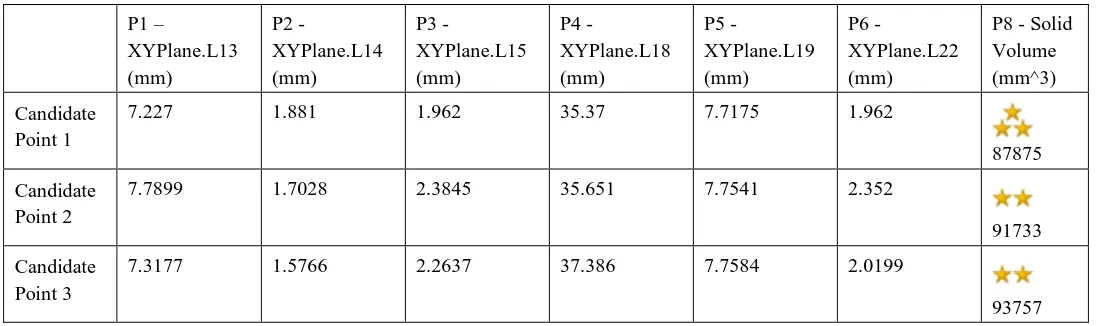
[image:6.612.33.582.569.732.2]Best candidates of the optimization study using Response Surface Optimization are as shown in table 4. Table 5 shows the ratings used.
Table 5 Candidate points of Solid Volume
P1 –
XYPlane.L13 (mm)
P2 -
XYPlane.L14 (mm)
P3 -
XYPlane.L15 (mm)
P4 -
XYPlane.L18 (mm)
P5 -
XYPlane.L19 (mm)
P6 -
XYPlane.L22 (mm)
P8 - Solid Volume (mm^3)
Candidate Point 1
7.227 1.881 1.962 35.37 7.7175 1.962
87875
Candidate Point 2
7.7899 1.7028 2.3845 35.651 7.7541 2.352
91733
Candidate Point 3
7.3177 1.5766 2.2637 37.386 7.7584 2.0199
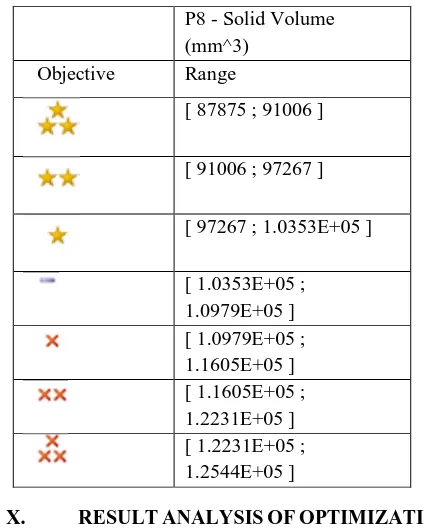
Table 6 Rating Values (Response Surface Optimization system)
P8 - Solid Volume (mm^3)
Objective Range
[ 87875 ; 91006 ]
[ 91006 ; 97267 ]
[ 97267 ; 1.0353E+05 ]
[ 1.0353E+05 ; 1.0979E+05 ] [ 1.0979E+05 ; 1.1605E+05 ] [ 1.1605E+05 ; 1.2231E+05 ] [ 1.2231E+05 ; 1.2544E+05 ]
X. RESULTANALYSISOFOPTIMIZATION
From minimization of surface volume it can be seen that candidate point 1 has got three stars, so for design of the piston the dimensions of the candidate point 1 must be taken into consideration.
XI. CONCLUSION
A comparison is made between piston made of Al alloy and Al composite. It is found that Al composite performs better than Al alloy. Optimization is done with an objective decreasing volume. It is observed for the objective of having minimum volume is met by choosing candidate point 1 as shown in table 5.
REFERENCES
[1] Dilip kumar sonar , Madhura Chattopadhyay “theoretical analysis of stress and design of piston head using catia & ansys International Journal of Engineering Science Invention Volume 4 Issue 6, June 2015 ,PP.52-61”
[2] Tadala akhil, K.Naresh, Abdul khurshid, Purushotham anil kumar "Analysis on Four Stroke Single Cylinder Engine Piston by using Aluminum Alloys (Al-GHS 1300, Al-Sic- Graphite, A6061, Pure Aluminum)", SSRG International Journal of Mechanical Engineering (SSRG - IJME), V3(1),4-12 January 2016. [3] Sundaram.K , Palanikumar.N “Investigation And Analysis Of Piston By Using Composite Material” Vol-2 Issue-6 2016”
[4] Kethavath Vishal, Dinesh Bajaj, A.Sai Kumar, " Design and Structural Analysis of Composite Piston ", International Journal & Magazine of Engineering, Technology, Management, and Research, ISSN No:23484845
[5] H.C.Anilkumar, H.S.Hebbar and K.S.Ravishankar, “Mechanical properties Of SiC Reinforced Aluminum Alloy Composites”, IJMME, 2011, Vol.6, Issue.1, pp. 41-45.
[6] B.S.Motgi, R Patil, “A Study on Mechanical Properties of SiC and Tib2 Reinforced Aluminum Alloy Composites”, IOSR,Vol. 7, Issue 6, 2013, pp.41-46. [7] Arun Kumar M. B. and R. P.Swamy, “Evaluation of Mechanical Properties of al6061, SiC and e-glass Fiber Reinforced Hybrid Metal Matrix Composites”,
ARPN, 2011, Vol.6, Issue.5
[8] Ch.Venkata Rajam, M.V.S.Murali Krishna, P.V.K.Murthy, G.M.Prasada Rao, "Design Analysis and Optimization of Piston using CATIA and ANSYS," International Journal of Innovative Research in Engineering & Science, vol. 1st, no. 2, pp. 41-51, 2013.