Fatemeh Kazemi1, Mohammad Hassan Neshati2, Farahnaz Mohanna3* 1Electrical Department, University of Sistan and Baluchestan, Zahedan, Iran
2Electrical Department, Ferdowsi University of Mashhad, Mashhad, Iran
3Electrical Department, University of Sistan and Baluchestan, Zahedan, Iran
E-mail: fatemeh.kazemi.ms@gmail.com, neshat@ieee.org, f_mohanna@hamoon.usb.ac.ir Received April 1, 2010; revised May 8, 2010; accepted June 16, 2010
Abstract
A Rectangular Dielectric Resonator Antenna (RDRA) fed by Dielectric Image Line (DIL) through a narrow slot placed on a finite ground plane is numerically investigated. The effects of ground plane size on the ra-diation performance of the antenna are analyzed. To increase the antenna gain, four sidewalls are placed around the corners of the ground. Also, a reflector is placed at the back side of the structures to reduce backward radiation. Results show that 7.7 dB gain is obtained at 10 GHz with a broadside radiation pattern. For the DRA with four sidewalls maximum gain of 10.4 dB at 10.4 GHz is achieved which is 2.7 dB higher than the gain of the structure without them. The effect of air gap between dielectric resonator and ground plane is also investigated. The results show that with increasing distance between the DR and ground, an-tenna gain is decreased.
Keywords:Dielectric Image Line (DIL), Dielectric Resonator Antenna (DRA)
1. Introduction
Microstrip lines are used to excite slot-coupled patch and DR antennas, while their transmission loss is high espe-cially at microwave and millimeter frequencies. To avoid conductor loss and to increase radiation efficiency, di-electric transmission line such as DIL could be used to excite a patch or a DRA through a narrow slot. The slot-coupled microstrip patch antenna and its array fed by the DIL were designed and investigated in [1], and a good gain, low return loss and low backward radiation were obtained. However, DRAs have been proposed as an efficient antenna at microwave and millimeter fre-quency, offering several advantages over the conven-tional microstrip patch antennas such as smaller in size, wider in bandwidth and no excitation of surface waves [2-5]. Moreover, due to no inherent conductor loss in dielectric materials, DRAs provide high radiation effi-ciency.
In this paper an RDRA fed by DIL, excited through slot on the ground plane is studied based on the Finite Element Method (FEM). The effects of the ground plane width are studied on the radiation performance of the DRA. Results show that the best width of the ground is nearly 100 mm for maximum gain and broadside
radia-tion pattern. The structure provides a good return loss with peak gain of 7.7 dB at 10 GHz. The slot length and width are 3.7 mm and 0.144 mm respectively.
To increase the DRA gain, four sidewalls are placed around the corners of the ground plane. Results show that maximum gain of 10.4 dB is achieved at 10.4 GHz which is 2.7 dB higher than the gain of structure without sidewalls. Moreover, to reduce the backward radiation, a reflector is placed at the back of the structure under the waveguide tapers. Results show that backward radiation is decreased nearly 10 dB in E-plane.
2. Antenna Structures
The geometry of the RDRA is shown in Figure 1(a). A rectangular DR of length a, width b, height c with the relative permittivity of εrd is placed on the ground plane
with width Wa. A slot of length L and width W is etched
at the center of the metal plane to excite the resonator. DIL as the transmission media consist of a rectangular dielectric slab of relative permittivity εr is placed under
(a)
[image:2.595.58.288.76.313.2](b)
[image:2.595.310.541.76.232.2]Figure 1. The geometry of the DRA fed by DIL. a) single antenna; b) antenna with four sidewalls.
Table 1. Antenna dimensions.
DRA DIL a 6.2 mm ad 4.25 mm
b 6 mm bd 4.03 mm
c 6.1 mm εr 10.2
εrd 10.2
3. Antenna Simulation
The structures are numerically investigated using HFSS based on the Finite Element Method (FEM) which cal-culates full 3-D electromagnetic field inside and outside (far field) of the structures [6]. The detailed structure of the RDRA defined in HFSS is shown in Figure 2(a). A standard metal waveguide, WR90 is used to excite the DIL, at the input and output of the transmission media. Three sections of waveguide using a proper tapering provide transition from TE10 mode of the metal
rectan-gular waveguideto dominant mode of the DIL [7]. The DRA structure has two ports. Port one is defined as the input to excite the TE10 mode of the metal waveguide.
The second port at the output is terminated to a matched load so; a traveling wave is propagated in DIL which efficiently excites the RDRA at the resonance frequency. The slot on the ground plane upon which the RDRA is located determines the amount of power coupled from the DIL to the resonator. The slot operates as a magnetic current in parallel to the resonator length exciting the RDRA at the principal TEz
111 mode of the operation [8,
9]. Figure 2(b) shows the detailed structure of the an-
(a)
(b)
Figure 2. Detailed feed structure of RDRA. a) antenna struc- ture; b) antenna with sidewalls and reflector plane.
tenna with sidewalls and PEC reflector. Height of side-walls is 0.25o, where o is the wavelength in free space.
4. Result and Discussion
4.1. Effect of Ground Plane Width
Figure 3(a) shows the effect of ground plane width on the RDRA peak gain. It can be seen that for low values of width antenna gain is very low. However, with in-creasing Wa backward radiation would decrease and
hence, antenna gain is increased. For Wa= 100 mm,
while the antenna structure is not too big, maximum gain is obtained. The antenna gain versus frequency for three values of Wais shown in Figure 3(b), which shows that
for 100 mm width 7.7 dB gain is obtained at 10 GHz. Return loss and radiation pattern for this width size are also shown in Figures 4(a) and 4(b) respectively. DRA structure provides broadside radiation pattern perpen-dicular to the ground plane and has good return loss.
4.2. Effect of Sidewalls
For increasing DRA gain, four sidewalls are placed around the corners of the ground plane. The height of sidewalls is chosen around 0.25o, while o is the wave-length in free space. Figure 5(a) shows the effect of sidewalls on RDRA peak gain. It can be seen that an-tenna gain is increased to 10.4 dB, while backward ra-diation is not reduced significantly and the resonance frequency is shifted about 0.4 GHz. Figure 5(b) shows the simulated radiation patterns at 10.4 GHz. It can also be concluded that backward radiation is high. It is said that this is due to radiation from slot and feed line.
4.3. Effect of Reflector
[image:2.595.63.279.368.436.2]0 25 50 75 100 125 15 0
2 4
0 (mm)
Wa (a)
9.0 9.5 10.0 10.5 11.0
0 2 4 6 8 10
Wa=60 mm
Wa=100 mm
Wa=140 mm Gain (dB)
[image:3.595.74.268.78.429.2](GHz) f (b)
Figure 3. RDRA Peak gain. a) versus ground plane width at 10 GH; b) versus frequency and different values of Wa.
as a reflector is placed at the back side of the structures. Its size is chosen same as the main ground. In this case, the radiation patterns are shown in Figure 6(a), which shows the backward radiation is significantly reduced. Also, the results show that maximum obtained gain of the RDRA with sidewalls and reflector is 10.4 dB at 10.4 GHz
9.0 9.5 10.0 10.5 11.0
-30 -20 -10 0
(GHz)
S11 (dB)
f
-5 -4 -3 -2 -1 0
(a)
[image:3.595.327.533.288.632.2](b)
Figure 4. RDRA with 100 mm of ground plane width. a) return loss; b) radiation patterns at 10 GHz.
9.0 9.5 10.0 10.5 11.0
0 3 6 9 12
(GHz) Gain (dB)
f
-5 -4 -3 -2 -1 0
(a)
[image:3.595.66.277.540.717.2](b)
Figure 5. RDRA with sidewalls. a) peak gain versus fre-quency; b)radiation patterns at 10.4 GHz.
(a)
9.0 9.5 10.0 10.5 11.0
-30 -20 -10 0
(GHz)
S11 (dB)
f
-5 -4 -3 -2 -1 0
[image:4.595.313.537.72.689.2](b)
Figure 6. RDRA with sidewalls and reflector plane. a) ra-diation patterns at 10.4 GHz; b) return loss.
0.0 0.2 0.4 0
0 2 4 6
.6 gap (mm)
[image:4.595.63.287.74.476.2]Gain (dB)
Figure 7. RDRA Gain versus air gap at 10.4 GHz.
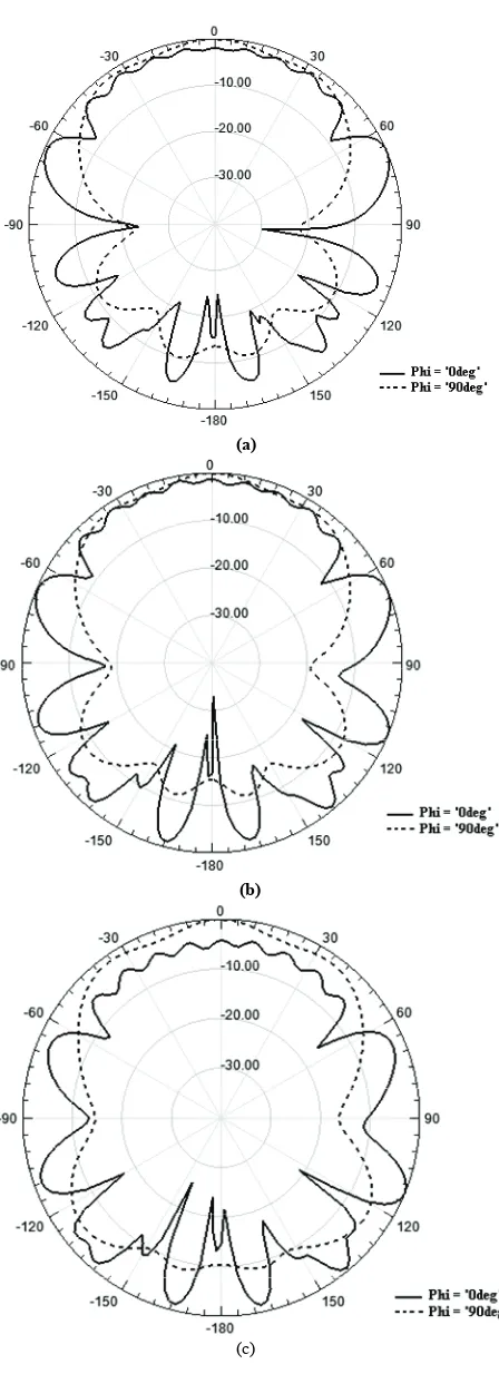
(a)
(b)
(c)
[image:4.595.67.273.519.689.2]ground surface or failure to ensure complete contact be-tween the DR and conducting parts of the RDRA struc-ture, may significantly affects the radiation performance of a DRA. When an air gap exists between the resonator and the ground, the electric field component normal to the metallic part of the structure is much stronger in air gap than the field component inside the resonator, espe-cially, when it is composed of a material of high dielec-tric constant.
To investigate the effect of air gap, a few simulation processes was carried out for different value of air gaps. The effect of gap on antenna gain is shown in Figure 7, which shows that for low values of distance between the resonator and ground, gain is high. However, with in-creasing air gap,antenna gain would decrease. Figure 8
shows the effect of air gap on radiation patterns of the antenna. It confirms that increasing the gap, would de-crease antenna gain.
5. Conclusions
In this paper a single RDRA excited by a DIL through a slot was numerically investigated by HFSS. The best ground plane width for maximum gain with a broadside radiation pattern was obtained. Results show that 7.7 dB gain at 10 GHz was obtained for 100 mm of ground plane width. Moreover, to increase antenna gain four sidewalls were added and maximum gain of 10.4 dB at 10.4 GHz was obtained which is 2.7 dB higher than the gain in case of structure without them. To reduce back-ward radiation, a reflector was placed at the back of the antenna structure. The results show that adding the re-flector lead to reduce the backward radiation around 10 dB in E-plane, especially. Also, the effects air gap between dielectric resonator and ground plane on the
[1] S. Kanamaluru, M. Y. Li and K. Chang, “Analysis and Design of Aperture Coupled Microstrip Patch Antennas and Arrays Fed by Dielectric Image Line,” IEEE Trans-actions on Antennas and Propagation, Vol. 44, No. 7, 1996, pp. 964-974.
[2] A. Petosa, “Dielectric Resonator Antennas Handbook,” Artech House Inc., 2007.
[3] A. A. Kishk, “Dielectric Resonator Antenna, a Candidate for Radar Applications,” Proceedings of 2003 IEEE Ra-dar Conference, Huntsville, May 5-8, 2003, pp. 258-264. [4] J. Shin, A. A. Kishk and A. W. Glisson, “Analysis of
Rectangular Dielectric Resonator Antennas Excited th- rough a Slot over a Finite Ground Plane,” IEEE Antennas and Propagation Society International Symposium, Salt Lake City, July 2000, pp. 2076-2079.
[5] Y. Coulibaly and T. A. Denidni, “Design of a Broadband Hybrid Dielectric Resonator Antenna for X-Band Appli-cations,” Journal of Electromagnetic Waves and Applica-tions, Vol. 20, No. 12, 2006, pp. 1629-1642.
[6] Ansoft Corporation, “HFSS: High Frequency Structure Simulator Based on Finite Element Method,” Vol. 11, Ansoft Corporation, 2003.
[7] H. Dashti, M. H. Neshati and F. Mohanna, “Numerical Investigation of Rectangular Dielectric Resonator An-tennas (DRAs) Fed by Dielectric Image Line,” Progress in Electromagnetic Research Symposium Proceedings, Moscow, Russia, August 18-21, 2009, pp. 1164-1168. [8] A. S. Al-Zoubi, A. A. Kishk and A. W. Glisson,
“Analy-sis and Design of a Rectangular Dielectric Resonator An-tenna Fed by Dielectric Image Line through Narrow Slots,” Progress in Electromagnetics Research, Vol. 77, 2007, pp. 379-390.