Michael Mazilu,1,∗ Yoshihiko Arita,1, 2,∗ Tom Vettenburg,1 Juan M. Au˜n´on,1 Ewan M. Wright,3, 1 and Kishan Dholakia1, 2, 3,† 1SUPA, School of Physics & Astronomy, University of St Andrews,
North Haugh, St Andrews KY16 9SS, United Kingdom.
2
MCRC, Molecular Chirality Research Centre, Graduate School of Advanced Integration Science, Chiba University, 1-33 Yayoi, Inage, Chiba, 263-0022, Japan.
3
College of Optical Sciences, The University of Arizona, 1630 East University Boulevard, Tuscon, Arizona 85721-0094, USA.
We demonstrate the transfer of orbital angular momentum to an optically levitated microparticle in vacuum. The microparticle is placed within a Laguerre-Gaussian beam and orbits the annular beam profile with increasing angular velocity as the air drag coefficient is reduced. We explore the particle dynamics as a function of the topological charge of the levitating beam. Our results reveal that there is a fundamental limit to the OAM that may be transferred to a trapped particle, dependent upon the beam parameters and inertial forces present.
The transfer of optical angular momentum to atoms, molecules and mesoscopic particles enables new funda-mental insights as well as applications. Spin angular mo-mentum is associated with the polarisation state of light whereas orbital angular momentum (OAM) is associated with an inclined wavefront resulting in an azimuthal com-ponent to the Poynting vector of the field. In the domain of manipulating mesoscopic particles, both types of an-gular momentum have been successfully transferred to microparticles in liquid and in air leading to innovative studies of microrheology [1–6] and a deeper insight into optical angular momentum transfer in both the parax-ial and non-paraxparax-ial regimes [7–9]. A recent emergent area is the area of optomechanics in vacuum enabled by optically trapped microparticles [10–14]. This opens the path to new studies of mesoscopic particles at the classical-quantum interface. Recently, we demonstrated transfer of spin angular momentum to trapped birefrin-gent microparticles in vacuum, reaching rotation rates in the MHz regime [15, 16]. OAM transfer in vacuum to a trapped particle promises novel and hitherto unrecog-nised perspectives for mesoscopic quantum studies. We draw analogies with the wealth of new science that has emerged from quantum gases and their interaction with light fields possessing OAM [17].
In this paper, we demonstrate the transfer of OAM to silica microparticles in vacuum. We explore particle mo-tion around the annular profile of a Laguerre-Gaussian beam, where the beam’s annular diameter is larger than the particle diameter. The trapping is two dimensional and relies on an interplay between the optical gradient and scattering forces, with contributions from inertial forces and gravity. Our experimental observations are supported by rigorous numerical analysis in the non-paraxial regime. Importantly, we see beam parameter re-gions where the particle leaves the trap indicating a fun-damental limit to the magnitude of OAM transfer that
∗MM and YA contributed equally to this work.
†Correspondence should be addressed to kd1@st-andrews.ac.uk.
can take place in such a system. Our work is the first experimental indication that a particle trapped in an op-tical vortex shows complex trapping force constants [18] and that stable periodic orbital motion requires the pres-ence of ambient damping.
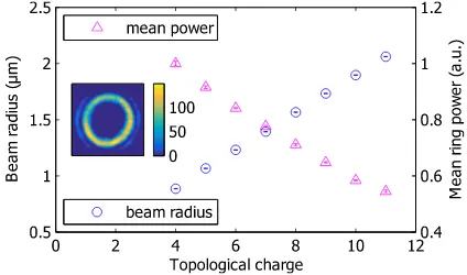
[image:1.612.333.545.532.657.2]A Laguerre-Gaussian (LG) mode possesses an OAM of `~ per photon [19], with ` the topological charge of the mode. For`6= 0, and radial mode index p= 0, the phase singularity on the beam axis results in a zero ax-ial intensity yielding an annular beam profile. OAM is transferred to a trapped object due to light scattering by the trapping field. We first investigated the beam prop-erties of the LG modes of a linearly polarised light beam. Fig. 1 shows the beam radius that scales linearly with the topological charge in the range of 4≤`≤11 [4, 20]. As the total power transmitted to vacuum is maintained constant up to` ≤ 20 (limited by the back aperture of the MO), the mean ring power of the beam annulus de-creases linearly with`by assuming that the beam waist remains constant for different`. Inset shows the annu-lar beam profile of`= 10 where the intensity variation on the annulus is about 30% for two standard deviations (2σ).
FIG. 1. Experimentally determined beam properties showing the annular intensity radius and mean ring power as a function of the topological charge.
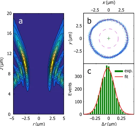
LG mode is determined by the interplay between a num-ber of parameters: The total torque transferred to the particle depends on the beam topological charge via the angular momentum per photon`~, the mean ring power P of the LG beam, the annular radius of the orbit r, as well as on the optical scattering properties of the par-ticle. The Stokes drag coefficient Γ of the residual gas molecules plays an important role in vacuum since the inertial force increases with rotation rate while the ra-dial trapping force remains constant. This effect changes the particle trajectories in both the lateral and axial trap-ping directions. Fig. 2b shows the trajectory of a silica sphere for the LG beam with`= 10 (see supplementary videos and Fig. 2a for a calculated beam profile), at a pressure of 16.39 kPa, obtained from the COM motion tracking using each individual frame (3,000 data points in total for 1 s). The dashed circle shows the location of the LG (`= 10) beam peak. The discrepancy between the particle trajectory and the LG beam peak position is caused by the increased inertial force counteracting the radial trapping force.
FIG. 2. Beam profile of the LG beam and trajectories of a silica particle. (a) Calculated profile of the LG beam (`= 10) cross-section at the centre of the annulus (nominal focus at z = 15µm from the glass substrate at z = 0). (b) Particle trajectories at a pressure of 16.39 kPa along with a fitted cir-cle (red solid line) and the beam circumference for the`= 10 beam (red dashed line) at focus. (c) Radial position distribu-tion for a particle around the fitted circle in (b).
The motion and trajectory of microparticles is highly dependent on the damping coefficient Γ. Fig. 3 shows the variation of the orbital radius and the orbital velocity as a function of Γ. We observe that as Γ decreases with lower pressure, the orbital velocity, ¯vincreases (Fig. 3b), which in turn increases the inertial force resulting in a wider orbital circumference than the beam annulus (Fig. 3a). Combining the measured orbital velocity and orbital ra-dius it is possible to calculate the inertial force,Fi, acting
on the particle. The gradient of the inertial force with respect to the orbital radius, ∆Fi/∆ryields a radial trap
stiffnessκr which in this case is 110.6 fN/µm, value that
is comparable to the values obtained from the equiparti-tion theorem (Fig. 2c).
FIG. 3. Dynamics of a silica particle with the LG beam of `= 10 depending on the damping coefficient Γ. (a) Orbital radius. (b) Orbital velocity. Error bars indicate 2σ.
It is of particular theoretical interest to understand the interplay between the optomechanical forces that deter-mine the particle dynamics. To elucidate this, we per-formed simulations in which a silica sphere of 5µm in diameter is levitated by spherically aberrated Laguerre-Gaussian beams with different topological charges (0 ≤
`≤15). The total optical power of 81.6 mW (measured at the back aperture of the objective) and the damp-ing coefficient, Γ (corresponddamp-ing to a residual pressure of 16.39 kPa) are kept constant in the simulation.
[image:2.612.67.290.304.510.2]number of the of optical momentum eigenmodes. In our specific case, about 800 modes are sufficient to describe the force acting of the particle. These optical eigenmodes correspond to orthogonal fields with respect to the mo-mentum transfer i.e. the momo-mentum transferred by any superposition of eigenmodes is equal to the sum of the momenta transferred by each eigenmode separately. The rest of the simulation corresponds to decomposing the incident beam onto these eigenmodes.
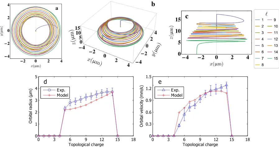
Figs. 4a-c shows the calculated orbital trajectories of a particle for different topological charges,`. As the index `increases so does the orbital radius of the particle mo-tion. This is expected as the increase in azimuthal force with` leads to an increase in beam diameter and, more importantly, a faster orbital rotation rate. This in turn leads to an increase in inertial force (centrifugal in this case) and thus to an increase in the orbital radial position with respect to the radial trap (Fig. 4d). This outward movement can be counteracted by the radial trap only up to a maximal orbital rate. In our case, this maxi-mal orbital rate is achieved for values larger than`= 14 (Fig. 4e). On the other hand, for ` smaller than 5 no orbital motion is observed as the diameter of the trap-ping beam is smaller than the diameter of the particle (Fig. 4e). This leads to a stable particle position in the centre of the beam thus cancelling the orbital azimuthal forces. It is also interesting to consider the case of a par-ticle placed within a perfect vortex beam [25], where the beam radius is independent of`. Here, we would observe increasing orbital speeds until the outward inertial force exceeds that of optical force in the system, when again the particle would leave its azimuthal trajectory.
We further remark that the axial position of the parti-cle changes with topological charge. This is linked to the variation of the “scattering force” acting on the particle and imparted by levitating beam. This upwards force counterbalances the gravitational force and can be seen, in a first approximation, to depend on the mean ring power (Fig. 1). We can think of the particle orbiting on the middle of an “optical funnel”. As the power density of the beam scales with`, the particle would find a dif-ferent axial equilibrium position, which is determined by the balance between the radiation pressure of the beam and the gravitational force on the particle.
In conclusion, we have described the first experimental demonstration of mesoscopic particle rotation in vacuum within a light field possessing OAM. Criteria for stable particle rotational motion have been established theoreti-cally and experimentally, demonstrating good agreement between experiment and numerical simulations. Our work shows that there is a limit to the possible OAM transfer to a trapped, orbiting particle. This effect was predicted theoretically [18] and can be understood con-sidering the direct link between the magnitude of the azimuthal index and the beam radius [20].
I. METHODS
Optical system. Our vacuum system uses a modifi-cation of the holographic optical trapping system used in our previous setup [6, 15]. A spatial light modula-tor (SLM, Hamamatsu LCOS X10468-03) is placed in a plane conjugate to the back aperture of the microscope objective (MO, Nikon, E-Plan 100×, NA=1.25) to allow for the generation of Laguerre-Gaussian beams with var-ious topological charges and three-dimensional position-ing of the Laguerre-Gaussian mode in the trap volume. The active surface area (16 mm by 12 mm) of the SLM is overfilled with a collimated continuous wave laser beam (IPG, YLM-5-LP, wavelength of 1070 nm), and the first diffraction order of a circularly-apertured blazed grating is used for modulation of the phase-front. An aperture at a plane conjugate with the sample is used to prevent unmodulated light from entering the vacuum chamber. Any aberration, including that caused by the divergence of the transmitted beam is compensated for by the SLM with the help of an auxiliary camera at a plane conjugate to the sample.
Particle levitation. Dry silica microspheres of 5µm in diameter (Thermo Scientific) are preloaded onto a circu-lar glass coverslip (Harvard Apparatus, 150µm in thick-ness) that is used as the vacuum chamber window for the trapping beam through the MO. A piezo electric trans-ducer (APC International) affixed to the chamber is op-erated at 140 kHz to detach microspheres from the lower glass window to load particles into the optical trap. Sin-gle silica spheres are trapped with a linearly polarised light field at an optical power of 81.6 mW (measured at the back aperture of the MO). Once a single sphere is trapped at atmospheric pressure, the chamber pressure is gradually reduced to∼10 kPa.
Stroboscopic imaging. To investigate the optome-chanics of a trapped particle in vacuum, we em-ployed a fast CMOS camera (Mikrotron GmbH, EoSens: 3.0 k fps) synchronised with pulses from a nanosecond laser (Elforlight, SPOT: wavelength of 532 nm, pulse width of.1 ns, pulse repetition rate of 3.0 kHz), which acts as a stroboscope at a sub millisecond time scale [15].
Data analysis. To establish the average orbital tra-jectory, we fit a circle with a radiusr (red solid line in Fig. 2b) to the particle’s COM motion. The particle’s po-sitional change ∆dbetween two successive frames (∆t= 0.33 ms) provides the orbital velocity ∆v= ∆d/∆t. Av-eraging this instantaneous velocity over multiple frames defines the average azimuthal velocity ¯v. The orbital ro-tation rate, Ω is then obtained as Ω = 2πr/v¯and the in-ertial force,Fi, can be determined asFi=mv¯2/r, where
mis the mass of the silica sphere (m= 1.19×10⁻¹³kg). The Stokes drag force, Fd, can also be calculated as
FIG. 4. Comparison between numerical simulations and experimental observations. (a-c) Numerical simulations of particle trajectories for different topological charges, `. Each panel shows top-, aerial- and side-views, respectively. (d-e) Measured versus calculated orbital radius and velocity as a function of topological charge`.
viscosity depending on the pressure. Here the local vis-cosity µ(P) in the vicinity of the microparticle is exper-imentally determined by taking the ratio of the rotation rates of a spinning vaterite microparticle between pres-sures of P and P0 where P0 is the reference pressure at 105Pa. In this case we can define the local viscosity as µ(P) =µ0Ω(P0)/Ω(P) whereµ0(P0) denotes the gas vis-cosity of air [15, 26]. By averaging the above quantities over a time interval (e.g. 100 ms), we determine a set of ten measurements, which is used to evaluate the standard deviation error for each measured quantity.
II. SUPPLEMENTARY INFORMATION
Supplementary videos (rendered at 25 fps from 3000 fps) show a trapped silica particle (5µm in diameter) orbiting either clockwise or anti-clockwise for the LG modes with `=±10 at a pressure of 16.39 kPa. The OAM transferred from the optical vortex drives the levitated silica sphere once around the circumference with an orbital rate faster than 50 Hz for a total optical power,P = 81.6 mW.
III. ACKNOWLEDGEMENTS
We thank the UK Engineering and Physical Sci-ences Research Council for funding (EP/J01771/X and EP/M000869/1) and Prof. Takashige Omatsu at Chiba University for useful discussions. KD acknowledges sup-port of a Royal Society Leverhulme Trust Senior Fellow-ship.
[1] O. Brzobohaty, M. Siler, J. Jezek, P. Jakl, and P. Ze-manek, Opt. Lett.38, 4601 (2013).
[2] M. E. J. Friese, T. A. Nieminen, N. R. Heckenberg, and H. Rubinsztein-Dunlop, Nature395, 621 (1998). [3] V. Garces-Chavez, D. McGloin, M. J. Padgett, W. Dultz,
H. Schmitzer, and K. Dholakia, Phys. Rev. Lett. 91, 093602 (2003).
[4] J. E. Curtis and D. G. Grier, Phys. Rev. Lett.90, 133901 (2003).
[5] K. Ladavac and D. G. Grier, Opt. Express 12, 1144 (2004).
[6] Y. Arita, A. W. McKinley, M. Mazilu, H. Rubinsztein-Dunlop, and K. Dholakia, Anal. Chem.83, 8855 (2011). [7] J. Courtial, D. A. Robertson, K. Dholakia, L. Allen, and
M. J. Padgett, Phys. Rev. Lett.81, 4828 (1998). [8] A. T. O’Neil, I. MacVicar, L. Allen, and M. J. Padgett,
Phys. Rev. Lett.88, 53601 (2002).
[10] T. C. Li, S. Kheifets, and M. G. Raizen, Nat. Phys.7, 527 (2011).
[11] J. Gieseler, B. Deutsch, R. Quidant, and L. Novotny, Phys. Rev. Lett.109, 103603 (2012).
[12] J. Millen, P. Z. G. Fonseca, T. Mavrogordatos, T. S. Mon-teiro, and P. F. Barker, Phys. Rev. Lett. 114, 123602 (2015).
[13] L. P. Neukirch, E. von Haartman, J. M. Rosenholm, and A. N. Vamivakas, Nat. Photonics9, 653657 (2015). [14] N. Kiesel, F. Blaser, U. Delic, D. Grass, R. Kaltenbaek,
and M. Aspelmeyer, P. Natl. Acad. Sci. USA110, 14180 (2013).
[15] Y. Arita, M. Mazilu, and K. Dholakia, Nat. Commun. 4, 2374 (2013).
[16] Y. Arita, M. Mazilu, T. Vettenburg, E. M. Wright, and K. Dholakia, Opt. Lett.40, 4751 (2015).
[17] S. Thanvanthri, K. T. Kapale, and J. P. Dowling, Phys. Rev. A 77, 053825 (2008).
[18] J. Ng, Z. F. Lin, and C. T. Chan, Phys. Rev. Lett.104, 103601 (2010).
[19] L. Allen, M. W. Beijersbergen, R. J. C. Spreeuw, and J. P. Woerdman, Phys. Rev. A45, 8185 (1992).
[20] M. J. Padgett, F. M. Miatto, M. P. J. Lavery, A. Zeilinger, and R. W. Boyd, New J. Phys.17, 023011 (2015).
[21] A. A. Ranha Neves, A. Fontes, C. L. Cesar, A. Camposeo, R. Cingolani, and D. Pisignano, Phys. Rev. E76, 061917 (2007).
[22] J. Baumgartl, S. Kosmeier, M. Mazilu, E. T. F. Rogers, N. I. Zheludev, and K. Dholakia, Appl. Phys. Lett.98, 181109 (2011).
[23] A. C. De Luca, S. Kosmeier, K. Dholakia, and M. Mazilu, Phys. Rev. A84, 021803(R) (2011).
[24] M. Mazilu, EigenOptics [Online]; University of St An-drews, St AnAn-drews, UK, 2015. DOI:10.17630/f039c29b-12fe-4b4b-9b0b-907c72634ad8 (accessed July 2, 2015). [25] M. Z. Chen, M. Mazilu, Y. Arita, E. M. Wright, and
K. Dholakia, Opt. Lett.38, 4919 (2013).