doi:10.4236/jilsa.2011.31006 Published Online February 2011 (http://www.SciRP.org/journal/jilsa)
Apply GPCA to Motion Segmentation
Hongchuan Yu, Jian Jun Zhang
National Centre for Computer Animation, The Media School, Bournemouth University, Poole, UK. Email: {hyu, jzhang}@bournemouth.ac.uk
Received October 14th, 2010; revised November 25th, 2010; accepted December 7th, 2010
ABSTRACT
In this paper, we present a motion segmentation approach based on the subspace segmentation technique, the genera-lized PCA. By incorporating the cues from the neighborhood of intensity edges of images, motion segmentation is solved under an algebra framework. Our main contribution is to propose a post-processing procedure, which can detect the boundaries of motion layers and further determine the layer ordering. Test results on real imagery have con-firmed the validity of our method.
Keywords: Generalized PCA, Motion Segmentation, Layer Ordering
1. Introduction
An important problem in computer vision is to segment moving objects of a scene from a video source, and part-ly recover the structure or motion information, such as foreground and background. With widespread demands on video processing, motion segmentation has found many direct applications. Video surveillance systems seek to automatically identify people, objects, or activi-ties of interest in a variety of environments with a set of stationary cameras. Motion segmentation can provide low level motion detection and region tracking cues. Another relatively new application is markerless motion capture for computer animation. It aims to estimate the human body configuration and pose in the real world from a video by locating the joint positions over time and extracting the articulated structure.
Motion segmentation is expected to partly recover the structure and motion information of moving objects from a mutually occluded scene. This includes the following main tasks, (1) labeling the regions of a motion layer segmentation, i.e. pixels are assigned to several motion layers; (2) finding their motion, e.g. each layer has its own smooth flow field while discontinuities occur be-tween layers; (3) determining the layer ordering, as the different layers might occlude each other. But motion segmentation is not equivalent to object tracking. Roughly speaking, object tracking is to track the seg-mented objects over an image sequence, although the extension of the rigidity constraint to multiple frames is nontrivial. Motion segmentation aims at the motion lay-ers of a scene rather than the moving objects. For exam-
ple, if a moving object contains multiple motions at a moment, it may be divided into several motion layers. When these motion layers share the same motion, they could be merged into a single layer. Hence, motion seg-mentation usually uses the information from a few suc-cessive frames. In contrast, object tracking focuses on a moving object in a scene. It utilizes the information from an image sequence. Motion segmentation plays a role of fundamental module in motion analysis and tracking. [1] presented a subspace segmentation method to estimate the motion models of the motion layers based on two successive frames. Built on this subspace segmentation method, this paper will further aim at two other basic problems of motion segmentation, i.e. the detection of motion layer boundaries and depth ordering based on two successive frames. The basic idea is to refine a global segmentation to solve these two problems. We first ad-dress this subspace segmentation approach for motion model estimation. We then incorporate it with the inten-sity edge information into a post-processing procedure, which refines the layer boundaries and infers the layer order between two successive frames. These two proce-dures form a complete algorithm for motion segmenta-tion. Our specific contributions in this paper include 1) the Polysegment algorithm (a special case of the genera-lized PCA [2]) is employed to detect the layer boundaries in our post-processing procedure, and 2) the cues from the intensity edges of images are utilized in the detection of the layer boundaries and depth ordering.
Previous Works
area of research, many issues remain open in computer vision, such as the layered motion descriptions [3,4], occlusion detection and depth ordering [5-7], and estima-tion of multiple moestima-tion models [8,9].
Most popular approaches to motion segmentation re-volve around parsing the optical flow field in an image sequence. Because of the well-known aperture problem, the motion vector from optical flow computation can only be determined in the direction of the local intensity gradient. For the sake of completeness of optical flow field, it is assumed that the motion is locally smooth. Obviously, depth discontinuities and multiple indepen-dently moving objects usually result in discontinuities of the optical flow. The usual approaches are to parameter-ize the optical flow field and fit a different model (e.g. 2D affine model) to each moving object, such as the layered representation of the motion field [3]. The chal-lenges of the optical flow-based techniques involve iden-tifying motion layers (or pixel grouping), detecting layer boundaries, and depth ordering. Previous research can mostly be grouped into two categories. The first category is to determine all of the motion models simultaneously. This can be achieved by parameterising the motions and segmentation, and using sophisticated statistical tech-niques to predict the most probable solution. For example, Smith et al. in [6] presented a layered motion segmenta-tion approach under a Bayesian framework by tracking edges between frames. In the implementation of their proposed scheme, the region edge labels were not direct-ly applied to the Bayesian model. They were implicitdirect-ly determined by the foreground-background orders of the motion layers and the motion layer labels for each region. Kumar et al. in [10] presented the learning approach of a generative layered representation of a scene for motion segmentation. In order to get the initial estimates of model, they utilized the loopy belief propagation, and further refined the initial estimate by using αβ-swap and
α-expansion algorithms. The large number of undeter-mined parameters in their Bayesian models leads to the difficult tracking problem in a high dimensional parame-ter space. The second category is the dominant motion approach [11-13]. A single motion is first fitted to all pixels, and then to test for pixels that agree with that mo-tion. This process can be repeated recursively on the out-lier pixels to provide a full set of layers [12].The central problem faced by this kind of approaches is that it is ex-tremely difficult to determine the occluded edges of the moving regions (or motion layers). Furthermore, this problem can result in the failure of depth ordering of motion layers. However, analytically reasoning such complex cases is impractical. The main reasons are three fold. First, the smoothing required by the optical flow algorithms makes it difficult to localize the layer
boun-daries. Second, the optical flow field is usually parame-terized by some 2D motion models (e.g. 2D affine), which is the first order approximation of the perspective model. It is unreliable to apply a 2D model to the boun-daries of moving regions. Third, pixels in a neighbor-hood of the boundaries are in the areas of high intensity gradient. Slight errors or image noise can result in pixels of a very different intensity, even under the correct mo-tion estimate [6]. In this paper, we will simplify the problem of motion segmentation based on an algebraic framework. We will first obtain a rough global segmen-tation and then refine it afterwards.
Our work is partially inspired by the subspace seg-mentation approach to motion model estimation pro-posed in [1]. This approach can provide a non-iterative and global estimation of motion layer segmentation. But it is incomplete, since the depth ordering and the detec-tion of layer boundaries are ignored. In this paper we provide a complete solution by developing a novel post- processing procedure using the intensity structures of edges for the detection of (1) motion layer boundaries and (2) the layer order.
In the remainder of this paper, we first briefly review the subspace segmentation approach to motion model estimation [1] in section 2. In section 3, a post-processing procedure is presented for the detection of the layer boundaries and depth ordering. The experimental results and analysis are given in section 4. Our conclusion and future work are given in section 5.
2. Motion Segmentation by GPCA-PDA
The core of our proposed motion segmentation approach is the scheme of segmenting hyperplanes in KR , which is called the generalized PCA (GPCA) in [2]. Applying the GPCA method to motion model estimation has been proposed in [1]. But the resulting motion model estima-tion can only yield coarse moestima-tion segmentaestima-tion, i.e. the boundary of the motion layers is very blurry. Our basic idea is to further refine the boundary of the resulting mo-tion layers by a post-processing procedure. Before intro-ducing our post-processing procedure, we firstly review the motion model estimation approach in [1] briefly. The two used algorithms, GPCA-PDA Alg. and Polysegment Alg., can be found in [2]. (We also briefly introduce these two algorithms in Appendix.)
The first problem to motion segmentation is to obtain the layered motion models corresponding to indepen-dently moving regions in a scene, (i.e. layer segmenta-tion). We address an algebra approach in terms of a known optical flow field which has been presented in [1]. Its distinct advantage over the other approaches is that it can determine all motion layers simultaneously.
, i
N1i u v
at the N pixels
1, 2
1N i i x x
, we can
de-scribe them through a affine motion as follows,
11 1 12 2 13
21 1 22 2 23 0 0
a x a x a u
a x a x a v
.
In terms of the hyperplane representation in the Ap-pendix, the solution to the multiple independent affine models can be rephrased as follows. Let
51, ,1, ,2
T
x x x u v R and hyperplane Si be spanned
by the basis of 1
11, 12, 13, 14,0
T
b a a a a and
2 21, 22, 23,0, 24
T
b a a a a . We need to segment a mixture of the hyperplanes of dimension d3 in R5, which is
expressed as,
5
1 2
: , T 0
i i
S xR b b x .
The original equations of optical flow have finished the projection from xR5 to two individual subspaces
of R4 in a natural way,
i.e. each new hyperplane in R4
can be expressed as,
a11,a12,a13,a14
x x x x1, , ,2 3 4
0.Applying the scheme of Equations (A1)-(A4) in Ap-pendix can yield the desired basis ( )
1, 2
i
i
B b b for each hyperplane Si in
3
R .
Up to now, one can obtain the initial estimation of all of the motion layers simultaneously. This is insufficient for motion segmentation, since we also need to determine the layer boundaries and the occlusion relationship. Be-side that, it can be observed that each segmented layer contains some small and isolated spurious regions, and the resulting layer boundaries wander around the real ones. This makes the detection of the layer boundaries difficult. The occluded regions take place in the neigh-borhood of the layer boundaries. If the occluding edges can be determined correctly, the occluded regions can be segmented correctly. Furthermore, the resulting motion layers can also be linked to the occluded regions in terms of the occluding edges for the depth ordering. Hence, it is a crucial step to determine the occluding edges. Our de-velopment is based on the following observations (1) the intensity edges include the boundaries of motion layers; (2) the layer boundaries are not always the occluding edges; (3) determining the occluding edges and inferring the occlusion relationship can be fulfilled by testing the neighborhood of edges.
We will introduce the intensity edges of images into the potential occlusion areas for the detection of occlud-ing edges in the next section.
3. Post-Processing Procedure
Let us consider a single viewpoint. The central problem
is to detect the occluding edges, because the erroneous edge labeling can cause incorrect depth ordering. Most of the techniques considered so far employed only the mo-tion field informamo-tion for momo-tion segmentamo-tion. For each frame, all edges, including edges of motion layers and textured edges of objects, are presented in the image in-tensity structure, which can provide the wealth of addi-tional information to motion estimation. Due to their ex-treme length, a number of measurements might be taken along (or around) them. This leads to a more accurate estimation of motion.
Recent applications have motivated a renewal of mo-tion segmentamo-tion by tracking edges [6,14]. Ogale et al. [7] classified the occlusions into three classes. In order to deduce the ordinal depth, they had to fill the occluded regions. This is to implicitly approximate the occluding edges by filling the neighborhood of the layer boundaries. [6] provides three fundamental assumptions of the rela-tionship between regions and edges to identify the edges of moving regions. We add an extra assumption (i.e. the 4th below) and emphasize these four assumptions as
fol-lows.
1) As an object moves all of the edges associated with that object move, with a motion, which may be approx-imately described by some motion model.
2) The motions are layered, i.e. one motion takes place completely in front of another, and the layers are strictly ordered. Typically the layer farthest from the camera is referred to as the background, with nearer foreground layers in front of this.
3)An arbitrary segmented image region only belongs to one motion model, and hence any occluding boundary is visible as a region edge in the image.
4) For each frame, the intensity edges involve the edges of motion layers.
An important conclusion from these four assumptions is that the layer ordering can be uniquely determined if the layer of each moving region is known and the oc-cluding edges are known. [7] presented the relationship of motion layers and occluded regions, and further em-phasized that the motion layer involving the occluded region must be behind another one. Even when the layers of motion regions are known, ambiguities may still be presented in the layer boundary labeling, as shown in
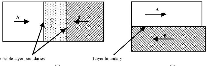
Figure 1. In Figure 1(a), due to the occluded region C, we can infer the occlusion relationship between the mo-tion regions A and B, while, in Figure 1(b), we cannot
[image:4.595.117.477.83.199.2]
(a) (b)
Figure 1. Illustration of moving regions (A,B) and occluded region (C). (a) The probable layer boundaries are determined by extending the moving region to the occluded region; (b) there is no occlusion region between layers A and B.
clude that the occlusion relationship hides behind the occluded regions, and identifying the occluding edges can reveal the occlusion relationship. The optical flow computation can usually identify the coarse occlusion regions as a by-product [15], which will be adopted in this paper.
The subspace segmentation approach described in sec-tion 2 is carried out on a given optical flow field instead of the image intensities. Due to the errors from the opti-cal field (e.g. aperture problem etc.), each resulting mo-tion layer contains two kinds of artifacts: (1) small iso-lated regions with texture and (2) dark holes over the image plane. It can be observed that a single hole in the middle of a foreground layer runs through to the back-ground layer. Similar problems also exist in the occluded regions. Moreover, the resulting boundaries of motion layers and their neighborhood are, in general, highly un-reliable areas. Therefore, the segmentation by the sub-space segmentation method and the occluded regions detected by the optical flow computation cannot offer a valid solution to the above two problems.
Consider the neighborhood of the layer boundaries. It can be observed that the occluded regions are involved in the neighborhood of the layer boundaries as shown in
Figure 1(a). The edges’ neighborhood contains the
wealthy intensity structures of image. This can provide us sufficient cues to find the layer boundaries and oc-cluding edges. We rephrase the problem of layer edge detection and depth ordering, and present our postpro-cessing procedure as follows.
The motion models of the layers are determined by the subspace segmentation approach described in section 2, while the layer boundaries and the layers of the occluded regions are undetermined. The problem we face here is how to determine the layer boundaries and infer the oc-clusion relationships. In order to do that, we will consider the intensity structures of each frame, the relevant occlu-sion region map (obtained by [15]) and the relevant boundary map of the initial motion layers (obtained by the subspace segmentation approach). Let us denote
in-tensity edge map as MI, occlusion region map as MO
and layer edge map as ML thereafter. The motion of
intensity edges dominates that of their neighborhood. It is straightforward to utilize the intensity structures of the neighborhood of the edges for detecting the layer boun-daries and inferring the occlusion relationship. The pro-posed post-processing procedure given below is per-formed over two successive frames, but evidence could be accumulated over an image sequence for a more ro-bust segmentation.
3.1. Construct Pending Areas
For each frame, we first determine some pending areas, which should involve all potential layer boundaries. Then, the detection of layer boundaries is carried out on the resulting pending areas accordingly. To this end, we place a set of windows w of size n n . along the edges of ML These small windows might be overlapped to
each other. Usually each window wi is determined by
the MO and ML without a fixed size, i.e. it is
ex-pected to be so large that the resulting set of windows can cover the occlusion regions MO and layer edge
map ML on the current frame. In our experiments, the
minimal size n of wi is set to 10 pixels.
3.2. Match Scores
Consider the resulting pending areas W
iwi, whichcontains many intensity edges lMI. The potential
layer boundaries are involved in MI. in terms of the assumption (4). Thus, for each window wi, we can
compute the profile of every point p, which is defined as a vector pf p
by sampling the intensity derivative inthe positive and negative directions of the intensity gra-dient at p. This is illustrated in Figure 2. The point
pro-file is then normalized as,
j j pf p pf p
pf p
. (1)According to the optical flow field, one can get a pair of corresponding points p and p respectively on two
A
A
B
B C
?
l
frame 1 frame 2
p
l
Normal line Refining & match score
[image:5.595.58.287.85.187.2]Match scores p
Figure 2. Illustration of point profiles and refining the matching point. Refining procedure is carried out as 1D search along the normal line on the frame 2.
successive frames. The match score is taken as the resi-dual error of their profiles as follows,
2 1 ( )
0 2
i i
pf p pf p
e p Exp
,
where is a reference distance and is determined em-pirically. When the point p is far away from layer boundaries, e0
p should approach one, i.e. the neighborhood of p obeys a single motion. Otherwise its neighborhood contains multiple motions. Furthermore, we can obtain other two match scores respectively along either side profile of the current point p, denoted as
1 , 2
e p e p . If point p belongs to a layer boundary, one of these two scores should approach one while the other should approach zero, otherwise both of them should approach one.
3.3. Matching
Because of the aperture problem, the motion of edges can only be determined in the direction normal to the edge. This means that the corresponding point p of the next frame (i1) lies on the normal line, which is the normal at point p on the current frame (i). This is useful as it restricts matching isointensity contour on the frame (i1) along the edge normal. In order to enhance the intensity edge matching, we add a new match score that is the re-sidual error e0
p of the profiles of p and p along the edge tangent line, which is shown in Figure 2.Refining the matching point p on the next frame (i1) is thus implemented as a 1D search based on the match score of
e0
p e0
p
along the direction of point
p’s gradient (i.e. the normal line) instead of point p’s gradient, which is also illustrated in Figure 2.After that,
one can re-compute the match scores e e e0, ,1 2 of the
points p and p in terms of their individual intensity gradients rather than the normal line.
3.4. Segmentation by Polysegment Alg.
Based on the match scores e e e0, ,1 2 in the pending areas
W , we apply the Polysegment algorithm as described in the Appendix respectively to the match scores of
0, ,1 2
e e e for the layer edge detection. There are two groups here, one is the group of layer edge points and the other is that of non-layer edge points. For each match score, we can thus get two cluster centers
( ) ( ) ( )
1 , 2 , 0,1, 2
i i i
i
. Moreover, to the points pW, there are eight cluster centers. The layer edge points should cluster around the two centers of
(0) (1) (2)
1 min , min , maxcent
and
(0) (1) (2)
2 min , max , mincent .
The segmentation of W is obtained as follows,
21, ,8
arg min j
j
i e p cent
, (2)
where e p
e e e0, ,1 2
p . On this basis, the points ofW can be classified into two groups, layer edge points and non-layer edge points.
3.5. Region Merging
For the group of non-layer edge points, one can merge most of small spurious regions in a big motion layer, i.e. merging small regions with a motion layer by comparing their areas with their individual neighbors’. This can lead to the connected layer. But it can be observed that the detected layer boundaries usually have discontinuities with the group of layer edge points, i.e. a set of layer edge segments. This is due to the fact that some layer edge points are incorrectly classified into the group of non-layer edge points. Based on the areas of the seg-mented layer regions, it is impossible to make a correct decision of region merging when these small regions may contain layer edge segments. This is because the layer edge segments indicate that the both sides should respectively occupy different motion layers and could not be merged into a single layer at anytime. These regions are thus left as the undetermined regions temporarily.
[image:5.595.87.262.271.317.2]the merging procedure should be terminated.
3.6. Depth Ordering
After region merging, one can obtain the desired bounda-ries of motion layers ML. If the occluded regions
be-long to a motion layer, this layer must be behind another one. Our problem can now be rephrased as HOW to as-sign the occluded regions to the known motion layers.
With the occlusion region map MO, one can first
de-termine which points of the layer boundaries belong to the occluding edges, since the layer boundaries involve the occluding edges. The worst case is that the points of the occluding edges are not within MO. But both side
profiles of these points should overlap with MO at that
moment. On this basis, one can determine the points of the occluding edges by checking if they are within MO
or their profiles overlap with MO. Since some points of
layer boundaries may not belong to the occluding edges, such as in Figure 1(b), the depth ordering can only carry
out on the detected occluding edges. Then, for the points of the occluding edges, one can extend their profiles in the direction of the intensity gradient to the known mo-tion layers for their profile labeling, i.e. inferring which layers both sides of the occluding edges respectively be-long to.
Furthermore, inferring the occlusion relationship can be fulfilled by comparing the match scores
1 , 2
e p e p of each point p of the occluding edges. This is because an occluded region only shares the same motion layer with one of the profiles of an occluding edge. The smaller match score corresponds to the real occlusion region. This implies that one side of an oc-cluding edge with the smaller match score is behind the other side, since it involves the occlusion region. In terms of the profile labeling of the occluding edge points, we can therefore find ordinal depth.
The Post-processing procedure is summarized as
follows:
1) Extracting the pending areas W on each frame; 2) Refining the corresponding points p on the next frame (i1), and then re-compute the match scores
0 , 1 , 2
e p e p e p ;
3) Applying the polysegment algorithm to the match scores of W for detecting the points of layer boundaries;
4) Merging the spurious regions for the continuous boundaries of the motion layers;
5) Determining the occluding edges in terms of MO;
6) Extending the profiles of the occluding edge points to the known motion layers for the profile labeling;
7) Comparing the match scores e1
p e, 2 p of theoccluding edge points p for depth ordering, i.e.
1 2
min e p e, p corresponds to the occluded region. This post-processing procedure and the subspace
seg-mentation approach described in section 2 constitute a complete algorithm of motion segmentation. Note that in our algorithm, the estimation of all the motion models in a scene is undertaken at the first procedure (i.e. subspace segmentation method), and the detection of the layer boundaries and depth ordering are carried out at the second procedure (i.e. post-processing procedure). This is different from the previous approaches. Usually the motion model estimation was mixed with the later processing. This makes the algorithms complicated and the implementation difficult.
4. Experiments and Analysis
Our algorithm was tested on several image sequences. In this section, the two results of the “flower garden” and “Susie calling” are presented. All programs have been implemented on the MatLab platform using a publicly available package—GPCA-PDA [16] and the optical flow code in [15]. All the image sequences used in our experiments are available at [17].
4.1. Flower Garden
In this experiment, we applied our motion segmentation approach to the flower garden sequence of resolution 175×120 pixels. The tree trunk in front of a garden is taken by a camera undergoing translation from the left to the right. Our goal is to determine the boundaries of the motion layers, and find the layer order over two succes-sive frames. Our approach found out two motion layers, the tree trunk and garden background.
Figure 3 gives the segmentation of the affine model
using the subspace segmentation approach described in section 2. It can be noted that the occlusion regions from the optical flow fields are crude, and contain many spu-rious small regions. The red arrows illustrate the possible occlusion regions in the successive frame 1 and 2. We show the results of motion segmentation of frame 1 in
Figure 3(1)-(3). Note that the occlusion regions in Fig-ure 3(2) and (3), which are not the layer boundaries, are
the interim areas between the foreground and background. It is impossible to determine the depth ordering using the obtained motion layers before determining the layers of the occluded regions. In addition, the resulting layer boundaries are also unreliable. Similar to the occluded regions, there are many small and isolated spurious re-gions on the obtained layers. We need to refine the layer boundaries and find out the layer order.
Figure 4 gives the segmentation results of the
frame 1 frame 2
[image:7.595.110.486.85.276.2](1). Occlusion regions (2). (3).
Figure 3. Motion segmentation results by the subspace segmentation approach only. (1) The occlusion regions from the opti-cal flow field between frame 1 and 2; (2) and (3) are the segmentation results only using the subspace segmentation approach described in section 2.
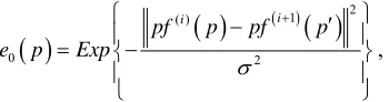
(1). Foreground (2). Background
(3). Intensity edge map (4). Occluding edges (red)
Figure 4. Refined and layered motion segmentation. (1) and (2) are the segmentation results; (3) the intensity edges of the image; (4) occluded region and occluding edges.
ground as shown in Figure 4(1). This is due to the fact
that the motion variance of this patch between the suc-cessive frames 1 and 2 is close to that of the “tree”, away from the background. If going through over multiple frames, the motion of this patch should be distinguished from the “tree”, since the motion of the ground is prone to be modeled by a single affine model. The intensity edge map of frame 1 is obtained by the Canny edge de-tector, and also shown in Figure 4(3). It can be observed
that the boundaries of motion layers are involved in the intensity edge map, e.g. the red arrows illustrate the cor-responding edges between the layer boundaries and the intensity edges of the image. Moreover, we also show the
occlusion edges (red) in Figure 4(4). Partial occluding
edges are not involved in the initial occlusion regions. But, the profiles of these edge points overlap with the occlusion regions. These points can thus be joined with the occluding edges. Additionally, it can be noted that the layer boundaries involve the occluding edges, but the layer boundaries are not always the occluding edges. Locating the occluding edges can help us find the depth ordering.
4.2. Susie Calling
[image:7.595.174.423.325.520.2]
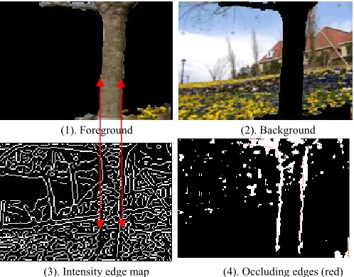
frame 1 frame 2 (1). Background (2). Phone regions
(3). Head region (4). Background (5). Phone regions (6). Head region
[image:8.595.103.493.82.306.2](7). Occluded region
Figure 5. The segmentation of the Susie calling. (1)-(3) are the results of the subspace segmentation method; (4)-(6) are the results of the post-processing procedure; (7) the layer boundary goes through the occluded regions.
pixels. It can be observed that the region of the phone is enwrapped by the head region. Our segmentation appro- ach aims at separating the phone region from the head region. The segmentation results are shown in Figure 5.
The region of phone is in front of the regions of head and background. The background region is behind the head region.
Due to the rich texture of the hair, the segmented head region contains many small holes, particularly in the hair area. It is difficult to determine the boundaries of the hair. For example, in Figure 5(2), a patch of hair image is
incorrectly classified into the group of the phone region. The post-processing could not merge this patch into the head region either, as shown in Figure 5(4)-(6). This is
because the detected layer edge segments goes through the occluded regions as shown in Figure 5(7). Moreover,
it has been judged that the regions of the phone and the hair patch are in front of the head region. This seems to be a bit strange. In general, the hair patch belongs to the head region. All the hair should be regarded as a whole body on the head and there is no occlusion to each other (unless the hairlines are considered). But it can be ob-served that the occluded regions overlying on the layer boundary appear at the bottom right of the image, i.e. around the boundaries between the shoulder and the hair. The motion of the hair is independent of that of the shoulder. The shoulder region is classified into the head region. Thus, it is acceptable to preserve this patch as an independent layer as shown in Figure 5(5).
5. Conclusions
In this paper, we proposed a novel approach for motion
segmentation based on the subspace segmentation tech-niques. The novelty is that by incorporating the intensity structures of images, our proposed approach can effec-tively detect the motion layer boundaries and the depth ordering. Different from the previous motion segmenta-tion approaches, our approach provides a non-iterative and global solution to motion segmentation under a uni-fied algebra framework, i.e. the generalized PCA [2,18].
However, it can be noted that our algorithm relies on a given optical flow field. In our experiments, many avail-able optical flow algorithms do not seem suitavail-able for the scenarios with a salient rotation element. This will re-strict the applications of our algorithm. It is crucial to further develop a robust optical flow algorithm. Our fu-ture work will aim to tackle this challenge.
REFERENCES
[1] R. Vidal and Y. Ma, “A Unified Algebraic Approach to 2-D and 3-D Motion Segmentation,” Journal of Mathe-matical Imaging and Vision, Vol. 25, No. 3, 2006, pp.
403-421. doi:10.1007/s10851-006-8286-z
[2] R. Vidal, Y. Ma and S. Sastry, “Generalized Principal Component Analysis (GPCA),” IEEE Transactions on Pattern Analysis and Machine Intelligence, Vol. 27, No.
12, 2005, pp. 1-15. doi:10.1109/TPAMI.2005.244 [3] J. Y. A. Wang and E. H. Adelson, “Layered
Representa-tion for MoRepresenta-tion Analysis,” IEEE Conference on Comput-er Vision and PattComput-ern Recognition, New York, 15-17
June 1993, pp. 361-366. doi:10.1109/CVPR.1993.341105 [4] R. Szeliski, S. Avidan and P. Anandan, “Layer Extraction
Trans-parency,” IEEE Conference on Computer Vision and Pattern Recognition, Hilton Head, 13-15 June 2000, pp. 246-253.
[5] M. J. Black and D. J. Fleet, “Probabilistic Detection and Tracking of Motion Boundaries,” International Journal of Computer Vision, Vol. 38, No. 3, 2000, pp. 231-245.
doi:10.1023/A:1008195307933
[6] P. Smith, T. Drummond and R. Cipolla, “Layered Motion Segmentation and Depth Ordering by Tracking Edges,”
IEEE Transactions on Pattern Analysis and Machine In-telligence, Vol. 26, No. 4, 2004, pp. 479-494.
doi:10.1109/TPAMI.2004.1265863
[7] A. S. Ogale, C. Fermuller and Y. Aloimonos, “Motion Segmentation Using Occlusions,” IEEE Transactions on Pattern Analysis and Machine Intelligence, Vol. 27, No.
6, 2005, pp. 988-992. doi:10.1109/TPAMI.2005.123 [8] D. J. Fleet, M. J. Black, Y. Yacoob and A. D. Jepson,
“Design and Use of Linear Models for Image Motion Analysis,” International Journal Computer Vision, Vol.
36, No. 3, 2000, pp. 171-193. doi:10.1023/A:100815620 2475
[9] W. Yu, G. Sommer and K. Daniilidis, “Multiple Motion Analysis: In Spatial or in Spectral Domain,” Computer Vision and Image Understanding, Vol. 90, No. 2, 2003,
pp. 129-152. doi:10.1016/S1077-3142(03)00011-0 [10] M. P. Kumar, P. H. S. Torr and A. Zisserma, “Learning
Layered Motion Segmentation of Video,” Proceedings of the 10th IEEE International Conference on Computer Vi-sion, Beijing, 17-20 October 2005, pp. 33-40. doi:10.110
9/ICCV.2005.138
[11] M. Irani, P. Anandan, J. Bergen, R. Kumar and S. Hsu, “Efficient Representations of Video Sequences and Their
Representations,” Signal Processing: Image Communica-tion, Vol. 8, No. 4, 1996, pp. 327-351. doi:10.1016/0923- 5965(95)00055-0
[12] M. Irani, B. Rousso and S. Peleg, “Computing Occluding and Transparent Motions,” International Journal of Computer Vision, Vol. 2, No. 1, 1994, pp. 5-16. doi:10.
1007/BF01420982
[13] G. Csurka and P. Bouthemy, “Direct Identification of Moving Objects and Background from 2D Motion Mod-els,” Proceedings of IEEE International Conference of Computer Vision, Kerkyra, 20-27 September 1999, pp.
566-571. doi:10.1109/ICCV.1999.791274
[14] T. Papadimitriou and K. I. Diamantaras, et al., “Video
Scene Segmentation Using Spatial Contours and 3D Ro-bust Motion Estimation,” IEEE Transactions on Circuits and Systems for Video Technology, Vol. 14, No. 4, 2004,
pp. 485-497. doi:10.1109/TCSVT.2004.825562
[15] A. S. Ogale and Y. Aloimonos, “A Roadmap to the Inte-gration of Early Visual Modules,” International Journal of Computer Vision, Vol. 72, No. 1, 2007, pp. 9-25. doi: 10.1007/s11263-006-8890-9
[16] Generalized Principal Components Analysis matlab codes available at http://perception.csl.uiuc.edu/gpca/ [17] Video sequences available at http://www.cipr.rpi.edu/
resource/sequences/
[18] R. Vidal, “Generalized Principal Component Analysis (GPCA): An Algebraic Geometric Approach to Subspace Clustering and Motion Segmentation,” Ph.D. Thesis, Electrical Engineering and Computer Sciences, Universi-ty of California at Berkeley, 2003.
Appendix
Segmenting Hyperplanes of Dimension K–1 in
K
R
Given a set of points
( )
1N
j K
j
X x R
in a homoge-neous coordinate system, and linear hyperplanes
1n K i i S R
of dimension ki dim
Si K1, weneed to identify Si. Usually the subspace is given as,
( )i 0, ( )i K
b x b R . Then, this hyperplane can be re- presented as,
K: T ( )i 0
i
S xR x b .
Furthermore, an arbitrary point x lies on one of the hyperplanes if and only if,
( ) 1 1 0 n T i n ix S x S x b
( ) 1 0 n T i n ip x x b
0 T n y c , where,
0 0 1 1 0 0 0
1 2 , 1 2 , , 1 1
T
n n n m
K K K K
y x x x x x x x x x R and m
n
c R is a coefficient vector consisting of a set of
monomials of { ( )i}
b and
1 ! ,
1 ! !
n K
m n K
K n
. For a
given point set X, we have a linear system on cn as
follows, (1) ( ) ( ) 0 ( ) T N
n n n
N T y x
L c c R
y x
(A1)
where, N m n
L R . When the number of hyperplanes n is known, cn can be obtained from the null space of
n
L . In practice, n is always determined in terms of Ln.
For a unique solution of the coefficient vector cn, it is
func-tion of variable n. In the presence of noise, let
irank L r when ni and 1
1 r r j j
, wherei
L is the data matrix with rankr, j is the jth sin-gular value of Li and is a given threshold.
For any x, we have pn
x c y xnT
. Each normalvector ( )i
b can be obtained from the derivatives of pn.
Consider the derivative of pn
x as follows
n
n T ( )i n ( )i T ( )jn
i
i j i
p x
p x x b b x b
x x
.For a point ( )l l
x S , ( )j T ( )l 0
j i
b x
for li. It can be noted that there is only one non-zero term in pn
x ,i.e.
( )l ( )i ( )j T ( )l 0 nj i
p x b b x
for li. Then, thenormal vector of Si is yielded as,
( ) ( ) ( ) l n i l n p x b p x (A2)
In order to get a set of points lying on each hyperplane respectively, so as to determine the corresponding nor-mal vectors b( )i , we can choose a point in the given
X close to one of the hyperplanes as follows,
( ) 0
arg min n n p x n p x i p x
, where xX (A3)
After given the normal vectors
( )ib , we can classify
the whole point set X into n hyperplanes in RK as
fol-lows,
( )
arg min T j , 1j
label x b j n (A4)
This algorithm is called GPCA-PDA Alg. in [2,18].
Polynomial Segmentation Algorithm
Consider a special case of piecewise constant data. Given N data points xR, we hope to segment them into an
unknown number of groups n. This implies that there exist n unknown cluster centers 1n, so that,
x1
xn
,which can be described in a polynomial form as follows,
0 1 0 n n kn i k
k i
p x x c x
(A5)To N data points, we have,
0 1 1 1 1 0 1 1 n n n n N N c x x L c c
x x
(A6)
where N (n 1)
n
L R and cRn1. Usually, the group
number is estimated as,
1
min : i i
n i (A7)
where i is the ith singular value of Li, which is the
collection of the first i1 columns of Ln, and is a
given threshold that depends on the noise level.
After solving the coefficient vector c of Equation (A6), we can compute the n roots of pn
x , whichcorres-pond to the n cluster centers { }n1 i i
. Finally, the seg-mentation of the date is obtained by,
21, ,
arg min j
j n
i x
(A8)