ISSN Online: 2327-4379 ISSN Print: 2327-4352
DOI: 10.4236/jamp.2019.78128 Aug. 23, 2019 1870 Journal of Applied Mathematics and Physics
Diffraction Pattern of a Rotated Grating
Pirooz Mohazzabi, Daniel J. Mattson, Joel Ambriz Ponce Jr.
Department of Mathematics and Physics, University of Wisconsin-Parkside, Kenosha, USA
Abstract
Diffraction patterns of a rotated grating are investigated from both theoretical and experimental points of view. It is shown that as the grating rotates, the angle of deviation of each diffracted line relative to the incident light goes through a minimum, and that the angle between any two successive diffracted lines goes through a minimum value which is the same for all adjacent dif-fracted lines. It is also shown that the angle between diffraction lines with
1
n= and n= −1 is not sensitive to small variations of the grating from being normal to the incident light. Finally, a method is suggested for deter-mining the line distance of a diffraction grating with high accuracy.
Keywords
Diffraction Pattern, Rotated Grating, Angle of Deviation
1. Introduction and Theory
Rotating diffraction gratings have a number of applications. For example, a pair of counter rotating diffraction gratings can be used in laser beam scanners for obtaining a linear scan rate for a flat field recorder [1]. The Doppler frequency shift in various diffraction orders produced as a result of a rotating radial fraction grating can be used for optical modulation [2]. Rotating all-glass dif-fraction gratings can be used as beam splitting frequency shifter in laser Doppler anemometers [3]. In this article, we study the general behavior of various dif-fracted lines as a result of rotation of the diffraction grating.
When a diffraction grating of line distance d is exposed to a light ray of wave-length λ, the general equation for the condition of constructive interference is given by [4]
(
sin sin)
d β− α =nλ (1)
where n is any integer, β is the angle of nth-order diffraction, and α is the angle of incidence. Both α and β are considered positive if measured coun-How to cite this paper: Mohazzabi, P.,
Mattson, D.J. and Ponce Jr., J.A. (2019) Diffraction Pattern of a Rotated Grating. Journal of Applied Mathematics and Phys-ics, 7, 1870-1876.
https://doi.org/10.4236/jamp.2019.78128
Received: July 14, 2019 Accepted: August 20, 2019 Published: August 23, 2019
Copyright © 2019 by author(s) and Scientific Research Publishing Inc. This work is licensed under the Creative Commons Attribution International License (CC BY 4.0).
DOI: 10.4236/jamp.2019.78128 1871 Journal of Applied Mathematics and Physics
terclockwise from the axis (normal to the diffraction grating) and negative if measured clockwise, as shown in Figure 1.
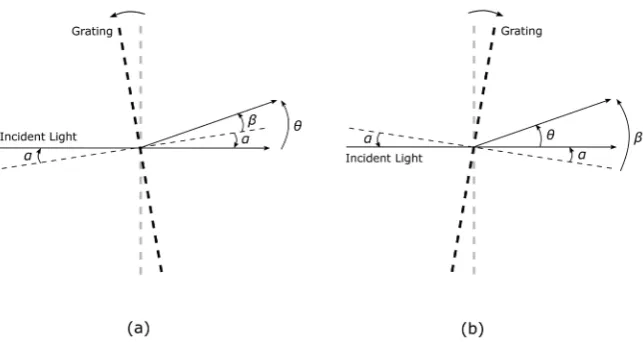
Now suppose that we illuminate a diffraction grating by a monochromatic ray of light of wavelength λ and then turn the grating, keeping the direction of the incident light fixed, starting from normal incidence, the angle through which the grating turns would become the angle of incidence for light, which is α in Eq-uation (1). However, instead of the diffraction angle β , let us study the angle of deviation θ between a diffracted beam and the incident beam, as shown in Figure 2. As in the case of α and β , the angle θ is positive if measured counterclockwise from the direction of incident light and negative if measured clockwise. Obviously, in terms of the deviation angle θ, Equation (1) can be written as
(
)
sin sin , 0, 1, 2,
d θ α+ − α=nλ n= ± ± (2)
[image:2.595.276.472.337.463.2]where α is negative if the grating turns counterclockwise (Figure 2(a)) and positive if the grating turns clockwise (Figure 2(b)).
Figure 1. Slant incidence of a monochromatic light on a diffraction grating. For the situation shown α and β1 are both positive.
Figure 2. A diagram showing the angle of deviation θ between a diffracted ray of light and the incident ray. The diffraction grating is rotated (a) counterclockwise (α<0) and
[image:2.595.213.535.507.678.2]DOI: 10.4236/jamp.2019.78128 1872 Journal of Applied Mathematics and Physics
The case n=0 is trivial and leads to θ =0. We are, however, interested in the higher-order diffractions and the behavior of θ as a function of α. We
shall only consider counterclockwise rotations of the diffraction grating (α<0) since clockwise rotations can be obtained from the former by a symmetry opera-tion on the experimental setup. From Equaopera-tion (2) we have
1
sin n sin
d λ
θ= − + α−α
(3) Let us investigate the behavior of this function, in particular, find out if there are any maxima or minima in θ,
2
d cos
1 d
1 n sin
d
θ α
α λ
α
= −
− +
(4)
This expression becomes zero when
2
1 n sin cos
d
λ α α
− + =
(5)
which reduces to
sin 2 n d λ
α = − (6)
and becomes infinity if
2
1 n sin 0
d
λ α
− + =
(7)
which reduces to
sin 1
n d
λ α
+ = ± (8)
In the last equation, the positive root will not be considered since it gives 0
α> (up to n=5 for the choice of λ =632.8 nm and d=3342 nm), cor-responding to a clockwise rotation. Therefore, the possibility of a minimum or maximum in Equation (3) exist only if one of the following conditions is satis-fied:
sin or sin 1
2
n n
d d
λ λ
α = − α = − − (9)
We now consider each case separately. Case 1: sin
2 n d λ α = −
For the counterclockwise rotations (α <0) that we are considering, we must have n>0. Furthermore, substituting the above equation into Equation (2), we obtain
(
)
sin
2 n d λ
DOI: 10.4236/jamp.2019.78128 1873 Journal of Applied Mathematics and Physics
Then adding the first of Equations (9) and (10) gives
(
)
sin θ α+ +sinα=0 (11)
or
2
2 sin cos 0
2 2
θ+ α θ
=
(12) which holds only if θ= −2α. It is easily verified that under this condition,
2 2
dθ αd >0, and hence θ is a minimum.
Case 2: sin 1 n d
λ α = − −
Clearly this can hold only if n<0 which corresponds to the diffracted rays below the normal to the grating (Figure 1). Substituting this result in Equation (1), we find sinβ= −1 or β = −π 2, which means that the diffracted ray is in the plane of the grating.
Therefore, our theoretical analysis shows that when the diffraction grating turns counterclockwise the diffracted rays with n>0 go through a minimum angle of deviation. The minimum angle of deviation for the nth-order diffracted beam takes place when the grating rotates through an angle αn relative to the
normal incidence, given by
1 sin
2
n
n d λ
α = − −
(13) The minimum angle of deviation for the nth-order diffraction is then given by
(
)
1min 2 2 sin
2
n n
n d λ
θ = − α = −
(14) There are no other minima or maxima in the angle of deviation.
2. Experiment and Results
In order to test these results, we used a diffraction grating with a line distance of 3342 10 nm
d = ± , and a 0.95 mW He-Ne laser (λ =632.8 nm). The line dis-tance of the grating was obtained by measuring it at ten different points of the grating, using the laser light.
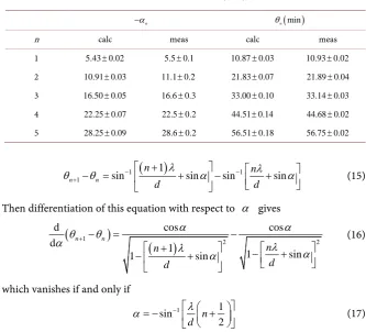
Table 1 shows the results of our measurements and their comparison with the calculated values. Each measured value reported in the table is the average of ten runs along with its standard deviation. The standard deviations of the theoretical values are calculated using propagation of errors and the standard deviation in d. As can be seen from Table 1, the agreement between the measured values and the calculated values is excellent.
DOI: 10.4236/jamp.2019.78128 1874 Journal of Applied Mathematics and Physics Table 1. Calculated and measured values of the rotation angle of the grating (−αn) at
which the angle of deviation becomes a minimum, θn
(
min)
. All angles are in degree.n
α
− θn(min)
n calc meas calc meas
1 5.43 0.02± 5.5 0.1± 10.87±0.03 10.93 0.02±
2 10.91 0.03± 11.1 0.2± 21.83 0.07± 21.89 0.04±
3 16.50 0.05± 16.6 0.3± 33.00 0.10± 33.14 0.03±
4 22.25 0.07± 22.5 0.2± 44.51 0.14± 44.68 0.02±
5 28.25 0.09± 28.6 0.2± 56.51 0.18± 56.75 0.02±
(
)
1 1
1
1
sin sin sin sin
n n
n n
d d
λ λ
θ θ − α − α
+
+
− = + − +
(15)
Then differentiation of this equation with respect to α gives
(
)
(
)
1
2 2
d cos cos
d 1 1 sin 1 sin n n n n d d α α θ θ
α λ λ
α α + − = − + − + − + (16)
which vanishes if and only if
1 1 sin 2 n d λ
α = − − +
(17) It can easily be verified that when this condition is met, θn+1−θn is a minimum.
Therefore, when α satisfies Equation (17), the angle between diffraction lines
of order n and n+1 becomes a minimum with a value given by
(
)
11 min 2 sin 2
n n
d λ
θ θ −
+ − =
(18) which is independent of n. Therefore the minimum angle reached between any two adjacent diffraction lines is the same.
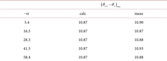
Table 2 shows the values of α and
(
θn+1−θn)
min calculated fromEqua-tions (17) and (18), respectively. In this case it was difficult to find the value of
α for which
(
θn+1−θn)
goes to a minimum by watching the diffracted beams,as both θn and θn+1 changed with α . We, therefore. measured θn and
1 n
θ + each as a function of α and then plotted θn+1−θn as a function of α.
The minimum of each graph did in fact take place at a value of α very close to that predicted by Equation (17). The measured values of
(
θn+1−θn)
min aregiv-en in the last column of Table 2.
DOI: 10.4236/jamp.2019.78128 1875 Journal of Applied Mathematics and Physics Table 2. Calculated and measured values of the minimum angle between adjacent diffraction line, and the rotation angles of the grating at which they occur. All angles are in degree.
(θn+1−θn)min
α
− calc meas
5.4 10.87 10.90
16.5 10.87 10.87
28.3 10.87 10.88
41.5 10.87 10.93
58.4 10.87 10.88
of the diffraction angles. In fact, it turns out that the angle between the diffrac-tion maxima with n=1 and n= −1 is not sensitive to small deviations of the grating from being normal to the incident beam. To see this we consider the an-gle between the diffraction maxima with n and −n:
1 1
sin sin sin sin
n n
n n
d d
λ λ
θ θ − α − α
−
−
− = + − +
(19) Taking the derivative of this angle with respect to α, we find
(
)
2 2
d cos cos
d
1 sin 1 sin
n n
n n
d d
α α
θ θ
α λ λ
α α
−
− = −
− + − −
(20)
which vanishes if and only if α =0. Therefore, the angle θ θn− −n having a
sta-tionary value at α =0, is not affected appreciably by small deviations of α from zero.
Finally, as an application of the above results, we rewrite Equation (14) as
(
min)
2 sin 2
n n
d λ
θ =
(21)
Since θn as a function of α has a very flat minimum, θn
(
min)
can bemeasured very accurately for a grating and hence the line distance d can be ob-tained from Equations (21) with high accuracy. Furthermore, in a single experi-ment data can be collected on several diffraction orders, resulting in a statisti-cally even more accurate measurement of d. In these measurements the task of making the diffraction grating perpendicular to the incident light, which is nor-mally required in the usual diffraction experiments, is eliminated.
3. Summary
mini-DOI: 10.4236/jamp.2019.78128 1876 Journal of Applied Mathematics and Physics
mum. Although this behavior has been reported by Lock [5], he only provided a semi-quantitative analysis of the problem based on two competing effects. Fur-thermore, Lock only considered the first- and second-order diffraction lines. In this work, we have provided a complete quantitative analysis of the problem and have considered up to the fifth-order diffraction.
Second, we have shown that the rotation angle of the grating that results in a minimum angle of deviation for a given diffracted line increases with the order of diffraction. As a result, the angle between any two successive diffracted lines first decreases and then increases, resulting in a minimum value which is the same for any two adjacent diffracted lines. This result has not been reported pre-viously.
Third, it is shown that the angle between diffraction lines with n=1 and 1
n= − is not sensitive to small variations of the grating from being normal to
the incident light, which justifies the commonly practiced procedure in diffrac-tion experiments, again, an observadiffrac-tion that is missing from previous investiga-tions.
Finally, we have suggested a new method for determining the line distance of a diffraction grating with high accuracy.
Acknowledgements
This work was supported in part by a URAP grant from the University of Wis-consin-Parkside.
Conflicts of Interest
The authors declare no conflicts of interest regarding the publication of this paper.
References
[1] Wyant, J.C. (1975) Rotating Diffraction Grating Laser Beam Scanner. Applied Op-tics, 14, 1057-1058. https://doi.org/10.1364/AO.14.001057
[2] Stevenson, W.H. (1970) Optical Frequency Shifting by Means of a Rotating Diffrac-tion Grating. Applied Optics, 9, 649-652. https://doi.org/10.1364/AO.9.000649
[3] Oldengarm, J. (1977) Development of Rotating Diffraction Gratings and Their Use in Laser Anemometry. Optics and Laser Technology, 4, 69-71.
https://doi.org/10.1016/0030-3992(77)90024-X
[4] Hecht, E. and Zajac, A. (1979) Optics. Addison-Wesley, Menlo Park, 357.
[5] Lock, J.A. (1985) The Rotated Diffraction Grating: A Laboratory Experiment. The