kink deformation. [doi:10.2320/matertrans.MI201216]
(Received November 26, 2012; Accepted January 24, 2013; Published March 8, 2013)
Keywords: magnesium alloys, long-period stacking/ordered phase, kink deformation, transmission electron microscopy
1. Introduction
Recently, Mg alloys with a small addition of TM (transition-metal atoms) and RE (rare-earth and Y atoms) have been of focused interests, since they are shown to reveal excellent mechanical properties such as strength greater than ³350 MPa with reasonable ductility, which can be realized by simply applying a conventional hot extrusion process for as-cast ingots.13) These excellent mechanical properties of the alloys are believed to be provided by long-period stacking/ordered (LPSO) phase,46) through its unique deformation behaviors referred to as“kink deformation”that causes the LPSO crystals to bend sharply by generating definite interfaces (i.e., kink-interfaces). It is generally known that kink deformation may preferably occur for anisotropic crystals owing to their limited slip systems such as an hcp crystal.7) Microscopic mechanism of the kink deformation was phenomenologically described by Hess and Barrett8)in terms of a sequential pile up of moving dislocations. In their model, dipole-pair dislocations are generated at buckling flexures, and then the dislocations with a same sign pile up to form a boundary across which the host crystals are sharply bended. Successive generations of such boundary lead to growing of kink bands. Later, Frank and Stroh9) further
discussed a mechanism of generating dipole-pair dislocations within grain interiors in the early stage of kinking. The dipole-pair generations and the pile-up behaviors of moving dislocations may fairly explain some representative features relevant to kink deformations; though, microscopic mecha-nism of kinking has not been fully understood yet because of significant lack of experimental investigations.
Regarding the plastic deformation behaviors of the LPSO-based MgZnY alloys, Hagihara et al.10,11) found that (0001)hcph1210ihcpbasal system provides a major slip mode, and other slip systems are restricted due to the anisotropic LPSO structures.1214) With the stress conditions that the Schmidt factor³0 with respect to the relevant slip planes,
deformation kinks seem to occur alternatively to account for the stress concentration. Kinking is generally known as a minor deformation mode in crystalline materials,15) but it appears to be an essential mode for the LPSO crystals, for which both the non-basal slip and twinning are strongly suppressed. Typical microstructures of the kink-deformation bands in the LPSO phase grains were shown to be represented by straight boundaries, across which the host crystals are sharply bended with rotational angles from 10 to 90 degrees.10,11,16)
During the microstructure investigations of the kink-deformed LPSO-based MgZnY alloy, we have occasionally found unique microscopic traces at the kink-boundaries, which are composed of multiply segmented kink-interfaces that are sequentially rotated with small angles to accomplish a large crystalline bending. This feature is reasonably interpreted as micro-kinking events. In the present work, we will describe details of micro-kinking structures and discuss their characteristics in terms of dislocation dipole-pair generations in the early stage of the kink deformation.
2. Experimental Procedure
The nominal composition of the MgZnY alloys used in the present work is Mg1 at%Zn2 at%Y (hereafter denoted Mg97Zn1Y2). Master alloy ingot was prepared by high
frequency induction melting of pure Mg (99.99 mass%), Zn (99.9 mass%) and Y (99.9 mass%) metals in a carbon crucible. Hot-extruded samples were prepared through an extrusion ratio of 10 at 623 K, with a ram speed of 2.5 mm s¹1 (see Yamasaki et al.,17) for further details of sample preparations). Thin foils for transmission electron microsco-py (TEM) observations were prepared by standard argon ion milling. Microstructures of the alloys were investigated with a JEM-2010 HC operating at 200 kV.
3. Results
the incident beam nearly along [1010] axis of the hcp-Mg matrix. In the image, a large number of kink interfaces are formed, dividing the LPSO phase grain into small distinct domains which are sequentially rotated in a same direction from left to right. This is confirmed by the corresponding electron diffraction pattern in Fig. 1(b), where the 000l reflections of the 18R-type LPSO crystals appear by rotating with respect to the common [1010]hcp axis up to about 36
degrees. Therefore, these micro-domain features are reason-ably interpreted as micro-kinking, which is essentially similar to those referred to as“sub-kink bands”.16)
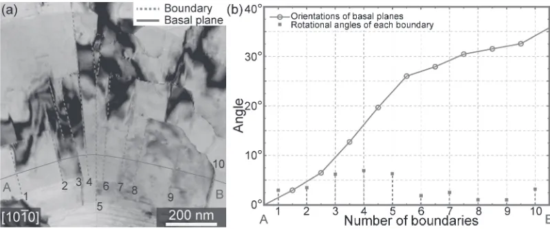
Figure 2(a) shows a magnified BF image of the micro-kinking region in the LPSO phase grain, in which the basal planes and the kink interfaces of each domain are represented by solid lines and dotted lines, respectively. It is seen that the distances between the kink interfaces are about several tens of nanometers apart from each other, and most of the interfaces are segmented and terminated within the LPSO crystals. By tracing the basal planes across the domains, the sequential rotation angles can be successfully measured, and the results are plotted in Fig. 2(b). It is clearly confirmed that all the basal planes rotate only in a clockwise along A to B in Fig. 2(a),
with the relevant rotational angles ranging from 17 degrees. These features may apparently be similar to the micro-twinning bands in some Mg alloys.18,19)However, it should be
noted in particular that the various rotation angles observed in Fig. 2(b) can never be explained by the primary and secondary twining of the LPSO crystals, suggesting that the micro-kinking is definitely different from the twinning event. Figures 3(a) and 3(b) show the BF images obtained from a part of Fig. 2(a), taken with two-beam conditions of g=1210 and g=00018; i.e.,a-excitation andc-excitation of the¡-Mg structure, respectively. Note that these excitation conditions just confirmed whether or not each of the dislocations possesses the relevant components. Namely, the precise burgers vectors of the dislocations can hardly be determined only from the present g·b analysis (e.g., the burgers vectors can either beh1210iorh1100iwhen successfully excited with g=1210). Because of this situation, we hereafter denote these dislocations asaA-dislocations andcA-dislocations, which do not represent any specific burgers vectors. In the image of Fig. 3(a), it is found that a number ofaA-dislocations are imaged as dark spots, which are semi-regularly arrayed along the kink interface.16) Localized appearances of the contrast
Fig. 1 (a): Bright-field TEM image obtained from a hot-extruded Mg97Zn1Y2alloy. (b): Electron diffraction pattern obtained from the
white-circle area in (a).
[image:2.595.107.488.68.261.2] [image:2.595.97.497.305.472.2]indicate that the dislocations are viewed as nearly edge-on conditions. It is noteworthy here that the aA-dislocations are not effectively excited at the adjacent kink interfaces in Fig. 3(a); this is perhaps due to the slight misorientations between the micro-kink domains. In fact, we indeed confirmed that the similar array of aA-dislocations was also emerged for other kink interfaces by slightly tilting the specimen to alter the excitation conditions. The relationship between dislocation densities at the interface and rotational angles across the kink interface is expressed by the equation;
tan½¼L=jbj ð1Þ
where the ½ is a rotational angle, L is an average interval length of dislocations, and«b«is an absolute value of burgers vector, respectively. For the kink interface in Fig. 3(b), ½ indicated by gray lines and L are measured to be about 2 degrees and 9 nm, respectively. Assuming b¼1=3h1210i,
«b«becomes 0.32 nm and hence the relevant½is calculated to be 1.9 degrees, which is almost equivalent to the observed value of 2 degrees.
Characteristic arrays of cA-dislocations are also formed in the vicinity of kink interfaces composed of the a A-dislocations, as indicated by white arrows in Fig. 3(b). Similar cA-dislocation arrays are frequently observed in the present kink-deformed specimen, even thoughcA-dislocations have been rarely observed for Mg alloys reported previ-ously.20) In Fig. 3(b), note that the cA-dislocations aligned
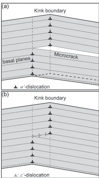
parallel to the basal planes, whose extensions will converge around the termination point of the kink-interface segment embedded within the grain interiors. It is also noteworthy that the cA-dislocation arrays can be traced by the relevant extra half planes (Fig. 3(c)), producing distinct line contrast along the basal planes, as frequently seen in Fig. 2(a). On the basis of this feature, we consider that thesecA-dislocations play an important role for the toughness of the LPSO-Mg alloys, as discussed below. Generally, it may naturally be expected that microcrack generations are an unavoidable consequence after the kink deformation, as schematically shown in Fig. 4(a).21) In fact, such microcracks have been frequently observed for several kink-deformed materials, e.g., hexagonal-BN,22)
SiC23) and Ti
3SiC2.24) For the LPSO crystals, however,
occurrence of microcracks seem to be effectively suppressed by generating the arrays of cA-dislocation, as illustrated in Fig. 4(b). Although a mechanism for emitting these
dislocations (perhaps within grain interiors) is not fully elucidated, the dislocation distributions in Fig. 4(b) fairly well explain the observed features as exemplified in Fig. 3. In any cases, such unique dislocation arrangements would contribute for avoiding microcracking and hence realizing a reasonable toughness of the LPSO-Mg alloys.
We also find a micro-kinking feature in a largely bended kink band. Figure 5(a) shows a BF image of a kink-deformed LPSO phase grain bended from bottom to top, whose rotational angle is estimated to be about 92 degrees from the electron diffraction patterns at X and Y regions. Looking at details of micro-kinks in Fig. 5(b), it is found that the microscopic features are almost similar to those described in
[image:3.595.94.502.70.205.2] [image:3.595.343.509.262.559.2]Fig. 2; domains divided by kink interfaces are sequentially rotated with small angles and all in a same direction, as confirmed by the relevant plot shown in Fig. 5(c). Accordingly, it is shown that micro-kinking is able to achieve a wide range of total bend angles, as observed for common kinking traced by singular sharp interfaces.
4. Discussion
We discuss the characteristics of the present micro-kinking in the LPSO crystals in terms of existing kink-deformation models.79)In the early stage of kink-deformation, one of the prominent role of dislocations are believed to be dipole-pair generations within a grain interiors, as illustrated in Fig. 6. As a consequence, a pair of kink interfaces composed of opposite edge dislocations will be generated, revealing a stepwise macroscopic feature of the kink deformation bands, as shown in Fig. 6. Note that, when all the kink interfaces are generated from dipole-pair dislocation walls, total rotation (bend) angles of the stepwise kink bands should appear to be zero. For the present micro-kinking structure observed in the largely bended kink bands, no set of dipole-pair dislocation walls was identified, and all the micro-kink domains are rotated along the same direction. Therefore, the
micro-kinking is hardly expected from the dipole-pair initiation models. Similar discussion was also made for micro-kinking feature in a kink-deformed Ti3SiC2.24)Although there is no
idea on how the dislocations have been generated in the early stage of micro-kinking in the LPSO crystals, it is worthwhile
Fig. 5 (a) Bright-field TEM image of the kink band taken nearly along [1210] direction. Electron diffraction patterns were obtained from the region represented as X and Y, respectively. (b) Magnified image of the rectangle region in (a). Interfaces and basal planes are represented by gray dotted lines and a solid line, respectively. Electron diffraction pattern was obtained from the white-circled area. (c): Plot of rotational angles of each kink interface.
[image:4.595.310.543.503.640.2]local stressfields significantly affect the microscopic features of kink bands. It may be presumed that, for the LPSO crystals, dipole-pair driven stepwise kinking preferentially occurs when the grains are attributed to a simple uniaxial compression stress.10,11) While, complicated kink deforma-tions including micro-kinking/rotational-kinking may occur when the grains are under multiple stress conditions such as represented by shear, bending, torsion, etc. Further inves-tigations are essentially necessary to clarify the microscopic mechanism of kink deformations of crystalline materials.
5. Conclusions
Microstructures of the LPSO phase kink bands formed in Mg97Zn1Y2 alloys have been investigated based on TEM
observations. We have found the unique microscopic features at the kink-boundaries, which are composed of multiply segmented kink-interfaces with small rotational angles; i.e., a micro-kinking features. The main results are summarized as follows.
(1) Electron diffraction patterns and BF-TEM images showed the occurrences of multiple kink interfaces which divide the LPSO phase grain into small domains. Based on the traces of the basal planes across the domains, it is confirmed that all the basal planes of the each domain rotate in a same direction with the relevant rotational angles smaller than 10 degrees, accomplish-ing a macroscopic large crystalline bend. These kinking features are apparently similar to the micro-twinning bands in Mg alloys; however, the presence of the various rotational angles suggests that the micro-kinking is different from the twinning phenomena. (2) Characteristic arrays of the dislocations were found
at the kink interfaces. The aA-dislocations are semi-regularly arrayed along the kink-interfaces with the various densities so as to rotate LPSO crystals across the kink-interfaces. The cA-dislocations are aligned parallel to the basal planes, whose extensions will converge around the termination point of the kink-interface segment embedded within the grain interiors. The characteristic arrangements of the cA-dislocations are expected to suppress the occurrence of micro-cracking, realizing the reasonable toughness of the LPSO-Mg alloys.
conducted in Research Hub for Advanced Nano Character-ization, The University of Tokyo, supported by MEXT. D. E was supported as a Japan Society for the Promotion of Science (JSPS) research fellows.
REFERENCES
1) Y. Kawamura and M. Yamasaki:Mater. Trans.48(2007) 29862992.
2) S. Yoshimoto, M. Yamasaki and Y. Kawamura:Mater. Trans.47(2006) 959965.
3) T. Itoi, T. Seimiya, Y. Kawamura and M. Hirohashi:Scr. Mater.51 (2004) 107111.
4) Y. Kawamura, K. Hayashi, A. Inoue and T. Matsumoto:Mater. Trans. 42(2001) 11721176.
5) A. Inoue, Y. Kawamura, M. Matsushita, K. Hayashi and J. Koike:
J. Mater. Res.16(2001) 18941900.
6) E. Abe, Y. Kawamura, K. Hayashi and A. Inoue:Acta Mater.50(2002) 38453857.
7) E. Orowan:Nature (London)149(1942) 643644.
8) J. B. Hess and C. S. Barrett: Trans. Metall. Soc. AIME185(1949) 599 606.
9) F. C. Frank and A. N. Stroh:Proc. Phys. Soc. London Sect. B65(1952) 811821.
10) K. Hagihara, N. Yokotani and Y. Umakoshi:Intermetallics18(2010) 267276.
11) K. Hagihara, Y. Sugino, Y. Fukusumi, Y. Umakoshi and T. Nakano:
Mater. Trans.52(2011) 10961103.
12) E. Abe, A. Ono, T. Itoi, M. Yamasaki and Y. Kawamura:Philos. Mag. Lett.91(2011) 690696.
13) H. Yokobayashi, K. Kishida, H. Inui, M. Yamasaki and Y. Kawamura:
Acta Mater.59(2011) 72877299.
14) D. Egusa and E. Abe:Acta Mater.60(2012) 166178.
15) A. G. Zhou and M. W. Barsoum:Metall. Mater. Trans. A40(2009) 17411756.
16) X. H. Shao, Z. Q. Yang and X. L. Ma:Acta Mater.58(2010) 4760 4771.
17) M. Yamasaki, K. Hashimoto, K. Hagihara and Y. Kawamura: Acta Mater.59(2011) 36463658.
18) H. Yoshinaga, T. Obara and S. Morozumi:Mater. Sci. Eng.12(1973) 255264.
19) Q. Yu, J. Zhang and Y. Jiang:Philos. Mag. Lett.91(2011) 757765.
20) J. Koike, T. Kobayashi, T. Mukai, H. Watanabe, M. Suzuki, K. Maruyama and K. Higashi:Acta Mater.51(2003) 20552065.
21) A. N. Stroh:Philos. Mag.3(1958) 625646.
22) S. Turan and K. M. Knowles:Phys. Status Solidi A150(1995) 227 237.
23) H. Suematsu, T. Suzuki, T. Iseki and T. Mori:J. Am. Ceram. Soc.74 (1991) 173178.
24) M. Barsoum, L. Farber and T. El-Raghy:Metall. Mater. Trans. A30 (1999) 17271738.
![Fig. 5(a) Bright-field TEM image of the kink band taken nearly along [1210�] direction](https://thumb-us.123doks.com/thumbv2/123dok_us/319582.530723/4.595.96.499.66.436/fig-bright-eld-tem-image-taken-nearly-direction.webp)
