Effects of Dual-Ion Irradiation on the Swelling of SiC/SiC Composites
Hirotatsu Kishimoto
1, Kazumi Ozawa
2, Sosuke Kondo
2and Akira Kohyama
1 1Institute of Advanced Energy, Kyoto University, Uji 611-0011, Japan2Graduate School Student, Graduate School of Energy Science, Kyoto University, Uji 611-0011, Japan
Silicon carbide (SiC) matrix composites reinforced by SiC fibers is a candidate structural material of fusion gas-cooled blanket system. From the viewpoint of material designs, it is important to investigate the swelling by irradiation, which results from the accumulation of displacement damages. In the fusion environment, (n,) nuclear reactions are considered to produce helium gas in SiC. For the microstructural evolution, a dual-ion irradiation method is able to simulate the effects of helium. In the present research, 1.7 MeV tandem and 1 MeV single-end accelerators were used for Si self-ion irradiation and helium implantation, respectively. The average helium over displacement per atom (dpa) ratio in SiC was adjusted to 60 appm/dpa. The irradiation temperature ranged from room temperature to 1400C. The irradiation-induced
swelling was measured by the step height method. Helium that was implanted simultaneously with displacement damages in dual-ion irradiated SiC increased the swelling that was larger than that by single-ion irradiated SiC below 800C. Since this increase was not observed above
1000C, the interaction of helium and displacement damages was considered to change above 800C. In this paper, the microstructural behavior
and dimensional stability of SiC materials under the fusion relevant environment are discussed.
(Received September 24, 2004; Accepted June 3, 2005; Published August 15, 2005)
Keywords: radiation damage, microstructure, dual-ion irradiation, SiC/SiC composites, fusion
1. Introduction
Fusion energy is one of the most desirable candidates as future energy resources. The energy efficiency of fusion is closely related to the blanket system. A gas-cooled blanket
operating above 1000C using SiC/SiC composites as
structural materials is expected to attain high energy efficiency. SiC materials with excellent mechanical proper-ties and microstructural stability at elevated temperature are
required under irradiation environments.1)It was difficult to
confirm the suitability of SiC/SiC composites as fusion materials, since the research on high-temperature irradiation effects were so limited. Other problems associated with employing SiC/SiC composites for fusion reactors were the synergistic effects of radiation damage and helium. The nuclear reaction by 14 MeV fast neutrons produces helium in SiC. Although the produced helium was expected to interact with the behavior of radiation damages, the precise details of
correlation were unclear.2)
The heavy-ion irradiation produces the cascade damage, which is similar to that of the 14 MeV fast neutron irradiation. The simultaneous irradiation of the heavy and helium ions is able to simulate the synergistic effects of cascade damage and helium. Thus the dual-ion irradiation
method has been employed in fusion materials research.3)
The other advantages of the dual-ion irradiation method have abilities of precise temperature control in a wide temperature range, time-saving during an experiment, and no radio-activity after the irradiation experiments. The microstructural
behavior of SiC at elevated temperatures above 1000C is not
well known. In this paper, the microstructural behavior and dimensional stability of SiC materials are investigated at very
high temperatures up to 1400C utilizing dual-ion irradiation
facility.
2. Experimental
2.1 DuET facility4)
Dual-Beam Material Irradiation Facility for Energy
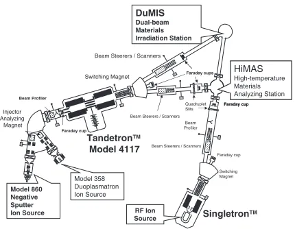
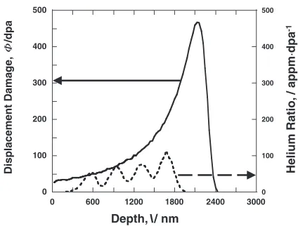
Tech-nology (DuET) Research Facility at the Institute of Advanced Energy, Kyoto University, was used for this research. For the irradiation experiments, the DuET facility with two accel-erators, 1.7 MeV tandem (Model 4117HC, HVEE B.V, Amersfoort, Netherlands) and 1 MeV single-end (HVEE B.V, Amersfoort, Netherlands), and two target stations were employed. Figure 1 shows the arrangement of equipments in the DuET facility. The target stations are located at the beamline junctions of the accelerators. The beams from both the accelerators intersect at the specimen surface in the target station. The tandem accelerator has a cesium sputter negative ion source (Model 860, HVEE B.V, Amersfoort, Nether-lands) for heavy-ion irradiation. Usually, the self-ion, Si ion for SiC, is selected to eliminate the effects of heavy-ion implantation. A single-end accelerator is used for helium implantation other than Si. An energy degrader is placed in the beamline to reduce the energy of helium ions in order to stop them at an appropriate depth in the target material. The depth profiles of displacement damages and helium concen-tration were calculated by TRIM codes using 5.1 MeV Si and 1 MeV helium ions as shown in Fig. 2. The implanted and
Beam Steerers / Scanners
Faraday cup TMP
TMP
TMP
TMP
TM
P
TMP
Injector Analyzing
Magnet Beam Profiler
Tandetron Model 4117
Switching Magnet Beam Steerers / Scanners
Switching Magnet
Singletron TM
TM Beam
Profiler Beam Steerers / Scanners
Quadruplet Slits
TMP Faraday cup
Faraday cups
Faraday cup
Faraday cup HiMAS High-temperature Materials Analyzing Station DuMIS
Dual-beam Materials Irradiation Station
Model 358 Duoplasmatron Ion Source
RF Ion Source Model 860
Negative Sputter Ion Source
[image:1.595.320.535.321.488.2]energy degraded helium ions were widely overlapped in the damaged range due to heavy-ion irradiation. The synergistic effects of displacement damages and helium can be inves-tigated from the microstructural behaviors in the overlapped range. Temperature control and measurement are also an important factor for analyzing the irradiation effects. Since the SiC research demands high temperature experiments
above 1000C, an additional graphite carbon heater was
attached to the specimen holder to realize high temperatures. A thermal-vision system (LAIRD3A, Nikon Co., Tokyo,
Japan) was used for in-situtemperature measurements. The
maximum temperature of this system was around 1500C.
2.2 Swelling investigation of SiC5)
Monolithic (3C)-SiC specimens produced by the
chemi-cal vapor deposition (CVD) process (Rohm and Hass Co., Woburn, USA) were used for the investigation of swelling. The disk-shaped specimens, size 3 mm in diameter and 0.25 mm in thickness, were cut and their surfaces were polished with diamond particles. The polished surface was covered with #200 molybdenum mesh. The irradiation experiments of single-ion (only Si ion) beam and dual-ion (Si ion and helium ion) irradiation were performed at up to 3 dpa. The irradiation temperature ranged from room
temper-ature to 1400C. The values of nominal flux and the helium
over dpa were110 3dpa/s and 60 appm/dpa,
respective-ly. The investigation of the swelling was performed by the step height method. The molybdenum mesh produced an unirradiated area on the surface. Steps were formed between the unirradiated and irradiated surfaces due to the swelling of irradiated SiC. Step heights were measured using an interferometric profilometry device (Micromap 128, Micro-map Co., Tucson, Arizona, USA), and the amount of swelling of SiC was calculated following the method reported in the
previous work.5)
2.3 Microstructural investigation of SiC/SiC compo-sites
The reinforcement of the SiC/SiC composites was attained by Tyranno-SA fiber (Ube Industries Co., Ube, Yamaguchi, Japan). This fiber is characterized by near-stoichiometric
composition and high crystallinity.6) The composites were
produced by the chemical vapor infiltration (CVI) method. Two kinds of interphases, namely pyrolytic carbon (PyC)
layer and C/SiC multilayer, were prepared.7)The composites
were then cut in square pieces and their surfaces were polished with diamond particles. The dimension of the
specimens was422mm3. A surface normal to the fiber
direction was selected for irradiation. The dual-ion irradi-ation was performed for these composites up to 100 dpa at
1000C. The flux and helium over displacement damage
ratios were110 3dpa/s and 60 appm/dpa, respectively. A
focused ion beam (FIB) processing was used for the preparation of TEM specimens from the irradiated SiC/SiC
composites.8) The thinned foils were cut off from the
materials and lifted using micro pick-up system. These foils were put on the carbon-film supported by copper grids. The microstructural investigation was carried out with a conven-tional JEOL JEM-2010 TEM.
3. Results
3.1 Swelling of irradiated-SiC
Figure 3 shows the swelling of -SiC under single-ion
irradiations at several irradiation temperatures. In the initial damage accumulation range, the swelling increases with an
increase in damage at all temperatures up to 1400C. The
swelling saturates to 3 dpa above 400C. The saturation could
not be confirmed at 200C. At 60C, the saturation occurred
at 1 dpa and the swelling reached to approximately 10%. The
amorphization in CVD-SiC irradiated at 60C was observed
by TEM. It was considered that amorphization caused a large
volume expansion at 60C.5) At temperatures higher than
400C, the saturation level of swelling tended to decrease
with increasing in irradiation temperature. This trend
continued up to 1400C. These swellings were considered
to be due to the accumulation of point defects. The temperature range showing characteristic microstructural behaviors of SiC are considered to be divided into three
stages,i.e., amorphization regime below 150C, point defect
regime below 1000C, and void swelling regime above
1000C.7,9)
0 100 200 300 400 500
0 100 200 300 400 500
0 600 1200 1800 2400 3000
Depth, l/ nm
Displacement Dama
g
e
,
/dpa
Φ
Helium Ratio,
/ appm
·
dpa
-1
Fig. 2 Depth profiles of displacement damage and helium ratio calculated by TRIM-98.
0.1 1 10
0.01 0.1 1 10
60°C
200°C
400°C
600°C
800°C
1000°C
1200°C
1400°C
Swelling, / %
Displacement Damage, Φ/dpa
Fig. 3 Temperature and displacement damage dependencies of swelling in
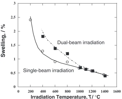
[image:2.595.62.274.70.231.2] [image:2.595.319.534.577.757.2]The behavior of saturated swelling under the single-ion irradiation and the effect of helium under the dual-ion irradiation are shown in Fig. 4. The irradiation dose rate was 3 dpa as in the Fig. 4. Under the single-ion irradiation, the saturated swelling decreased with an increase in the
irradiation temperature up to 1400C. The trend observed
in the dual-ion irradiated SiC was the same as that of the single-ion irradiated materials. But the absolute amounts of
swellings were increased by the presence of helium on-SiC
below 1000C. However, this increase in swelling due to
presence helium was not observed above 1000C. Thus, the
interaction between displacement damage and helium seems
to change above 1000C.10)
3.2 Microstructural evolution in SiC/SiC composites under dual-ion irradiation
Since SiC is a brittle material, SiC fiber reinforced SiC matrix composites have been developed to be employed as structural materials for fusion and fission systems. The fibers, matrix, and interphases in a SiC/SiC composite are affected by irradiation or damage accumulation. The swelling of SiC fibers often determines total performance of SiC/SiC composites. A highly crystallized SiC fiber was expected to have stable microstructure under irradiation environments; therefore, Tyranno-SA fibers having stoichiometric and crystallized structure were developed. Another important aspect was the performance of matrix/fiber interphase. In order to investigate the behavior of the interphase under irradiation environments, two kinds of interphases were developed. Figure 5 shows the TEM images of a pyrolytic carbon (PyC) monolayer interhase and a C/SiC multilayer interphase. Figure 5(a) shows a PyC interphase that is approximately 600 nm thick. The C/SiC multilayer in Fig. 5(b) has 5 thin carbon layers in the SiC matrix. Each carbon layer is approximately 25 nm thick and the diameter
of SiC fibers is approximately 10mm. Figure 6 shows a
cross-sectional TEM image of Tyranno-SA/multilayers/CVI-SiC composite after the dual-ion irradiation at 100 dpa and
1000C. The helium implanted range was between 400 nm
and 1900 nm depth from the specimen surface. Fractures and
the shrinkage of Tyranno SA fiber were not observed.11)The
dimensional changes of Tyranno SA fiber appeared to be the same as in the case of the CVI-SiC matrix. The multilayer interphase appeared to be stable because cracks and debondings of interphase were not observed. The thickness of each layer tended to decrease with an increase in the damage. This phenomenon suggests the possibility that a thin carbon layer may have been lost in a heavy dose irradiation environment. The cross-sectional TEM image of Tyranno-SA/PyC/CVI-SiC composites after the dual-ion irradiations
of up to 100 dpa at 1000C is shown in Fig. 7. The irradiated
range of the PyC interphase was apparently thicker than the unirradiated range. The border of irradiated and unirradaited range of interphases was broken during FIB processing in Fig. 7.
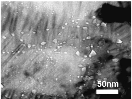
Although helium effects were not detected on the PyC interphase, implanted helium affected the microstructure of CVI-SiC matrix. Figure 8 shows a TEM image of the helium cavities in CVI-SiC matrix after the dual-ion irradiation at
1000C and 100 dpa. The amount of cavity swelling in the
CVI-SiC was calculated as approximately 0.3%.12) Some
very fine cavities were observed on the grain boundaries on Tyranno-SA fibers, although, their quantitative analysis was difficult owing to their extremely small size.
0 0.5 1 1.5 2 2.5 3
0 200 400 600 800 1000 1200 1400 1600
Dual-beam irradiation
Single-beam irradiation
Swelling, / %
Irradiation Temperature, T/ °C
Fig. 4 Temperature dependence on swelling of SiC dual- and single-ion irradiated to 3 dpa.
300nm
(a)
(b)
Fig. 5 TEM micrographs of interphases (a) pyrolytic carbon (PyC) layer (b) C/SiC multilayer.
500nm Dual-ion
irradiated range
Damaged rang
Matrix Fiber
[image:3.595.63.277.72.246.2] [image:3.595.310.543.73.216.2] [image:3.595.321.536.270.461.2]4. Discussion
The most important reason for the degradation of mechan-ical properties of early SiC/SiC composites was a large shrinkage of SiC fibers during the irradiation. The matrix and
fiber debonding resulted in this reduction.13) Since the
amorphization of SiC leads to a large volume expansion of SiC, the recent advanced SiC fibers including Tyranno-SA are crystallized very well to prevent the degradation of mechanical properties, which is due to the debondings at the carbon interphase. The swelling behaviors of CVI-SiC matrix and Tyranno-SA fiber were almost the same in this research. Although the crystallization of the amorphous SiC phase in fibers causes a large shrinkage of SiC fibers, the interphases fracture was not observed in this research. The crystallized SiC fibers such as Tyranno-SA, having stoichiometric composition, are considered not to shrink under the irradi-ation environment.
The helium effects on Tyranno-SA fibers were observed to be slightly different from those in the CVI-SiC matrix. Extremely small cavities were observed on the grain
boundaries in Tyranno SA. Thus, helium migration and helium cavity formation were assumed to occur above
1000C. The helium effects on the amount of swelling
disappeared above 1000C, as shown in Fig. 4. Below 800C,
since the swelling of dual-ion irradiated SiC was larger than that of single-ion irradiated SiC, the implanted helium was considered to be trapped at vacancies and prevent the progress of the recombination of interstitials and vacancies. The release of the trapped helium from vacancies is estimated
to commence at 800C.14)Thus, the void formation regime
may start above 800C and the helium cavity induced
swelling may occur above 800C. The released helium is
expected to migrate to grain boundaries and form helium cavities when the helium concentration on grain boundaries reaches a threshold. The CVI-SiC matrix was denser than the Tyranno-SA fibers, and had larger grains than Tyranno-SA fibers. Because the density of grain boundary on CVI-SiC matrix was less than that of the Tyranno-SA fibers, the density of trapping site for migrating helium in the CVI-SiC was also less than that of in the Tyranno-SA fibers. Thus, it was assumed that the number of helium cavities in the CVI-SiC matrix was greater than that in the Tyranno-SA fibers. The interphases did not debond from matrix and fiber, and thus a significant degradation of mechanical properties was not expected to occur in the Tyrrano-SA reinforced
compo-sites. The increase in swelling due to helium cavity at 1000C
and 100 dpa was calculated to be approximately 0.3%, which was not a significantly large expansion.
The mechanical properties of SiC/SiC composites depend on the performance of interphases. In this research, the trends in microstructural behavior of carbon interphases under the irradiation environment were clarified. The construction of carbon interphases also need to be improved for further research in this field. This research showed that a volume expansion and a slight reduction in thickness of a carbon layer occur simultaneously. The former phenomenon is supposed to be the result of an increase in the lattice spacing
of carbon layers,15)while the reason for the latter
phenom-enon is unclear and the slight swelling of SiC or the irradiation-induced mixing of carbon are suggested to be responsible for it.
5. Conclusion
The dual-ion irradiation research for SiC and advanced SiC/SiC composites was performed. The swelling of SiC depended on the irradiation dose, irradiation temperature, and implanted helium. The saturation swelling of SiC decreased with increasing in the irradiation temperature up
to 1400C. The helium existence increased the swelling
below 800C. Above 1000C, the helium effects were
observed as the formation of helium cavities in SiC. The advanced SiC/SiC composite using the crystallized SiC fiber reinforcements seems to have a fair dimensional and
micro-structural stability at 1000C after the dual-ion irradiation of
up to 100 dpa in this research.
Acknowledgement
The dual-beam ion irradiation experiment was carried out
300nm
Irradiated range
Unirradiated range
Matrix Carbon Fiber
IInterphase
Fig. 7 Swelling of Pyrolytic carbon (PyC) interphase after dual-ion irradiation at 1000C and 100 dpa.
50nm
[image:4.595.62.276.72.268.2] [image:4.595.61.276.322.483.2]with the assistance of Drs. H. Sakasegawa, K. H. Park, K. Jimbo, H. Suzuki, and H. Ogiwara, Institute of Advanced Energy, Kyoto University. The authors would like to extend their heartiest thanks to Dr. Y. Katoh at ORNL for his useful discussion and help.
REFERENCES
1) R. H. Jones, L. L. Snead, A. Kohyama and P. Penici: Fusion Eng. Des.
41(1998) 15–24.
2) P. Fenici, A. J. Frias Rebelo, R. H. Jones, A. Kohyama and L. L. Snead: J. Nucl. Mater.258–263(1998) 215–225.
3) S. Ishino: J. Nucl. Mater.239(1996) 24–33.
4) A. Kohyama, Y. Katoh, M. Ando and K. Jimbo: Fusion Eng. Des.51– 52(2000) 789–795.
5) H. Kishimoto, Y. Katoh, A. Kohyama and M. Ando: Effects of Radiation on Materials, ASTM STP-1405 (2001) 775–785.
6) T. Ishikawa, Y. Kohtoku, K. Kumagawa, T. Yamamura and T. Nagakawa: Nature391(1998) 773–775.
7) L. L. Snead, M. C. Osborne, R. A. Lowden, J. Strizak, R. J. Shinavski, K. L. More, W. S. Eatherly, J. Bailey and A. M. Williams: J. Nucl. Mater.253(1998) 20–30.
8) Y. Katoh, A. Kohyama and T. Hinoki: Eur. Conf. Comp. Mater. Sci. Technol. Appl.4(1998) 351–357.
9) S. Kondo, K. H. Park, Y. Katoh and A. Kohyama: Fusion Sci. Technol.
44(2003) 181–185.
10) H. Kishimoto, Y. Katoh, K. H. Park, S. Kondo and A. Kohyama:
Advanced SiC/SiC Ceramic Composites: Developments and Applica-tions in Energy Systems, Ceram. Trans.144(2002) 343–352. 11) H. Kishimoto, Y. Katoh and A. Kohyama: J. Nucl. Mater.307–311
(2002) 1130–1134.
12) S. Nogami, A. Hasegawa, K. Abe, T. Taguchi and R. Yamada: J. Nucl. Mater.283–287(2000) 268–272.
13) Y. Katoh, M. Kotani, H. Kishimoto, W. Yang and A. Kohyama: J. Nucl. Mater.289(2001) 42–47.
14) A. Hasegawa, B. M. Oliver, S. Nogami, K. Abe and R. H. Jones: J. Nucl. Mater.283–287(2000) 811–815.