Aspects of the Application of Electrochemistry to the Extraction of Titanium
and Its Applications
Derek Fray
1and Carsten Schwandt
1,21Department of Materials Science and Metallurgy, University of Cambridge, 27 Charles Babbage Road, Cambridge CB3 0FS, UK 2Department of Materials Science and Metallurgy, University of Nizwa, Birkat Al Mouz, 616 Nizwa, Oman
For over five decades the main route for the extraction of titanium has been the Kroll process. It is regarded as being expensive, labour intensive, reliant on a high quality feedstock, and environmentally unfriendly, but it has thus far not been possible to replace it. As a result the usage of titanium is still restricted to a few high end applications. During the past twenty years several new molten salt based electrochemical approaches for the reduction of titanium oxide have been introduced to meet these challenges, and these may, eventually, lead to novel extraction processes for titanium and other reactive metals. This paper summarises the many interesting concepts that underlie these electrochemical meth-ods, of which some have already advanced to the stage of substantial pilot plants whilst others are still being developed at the laboratory level. The paper also reviews the development of new materials for use as the anode in these processes. Finally, it touches upon the development of processes for the regeneration of oxidised titanium and for the welding of titanium under cathodic protection in cases where protective gas shielding is not possible. [doi:10.2320/matertrans.MK201619]
(Received September 2, 2016; Accepted November 14, 2016; Published January 16, 2017)
Keywords: titanium, extraction, electroreduction, electrorefining, regeneration, welding, molten salt, electrolysis, inert anode
1. Introduction
The vast majority of titanium (Ti) is produced by the Kroll process, which was developed in the late 1930s and success-fully commercialised in the 1950s1). In the main it comprises the steps of: carbochlorination of a high purity titanium diox-ide (TiO2) feedstock to titanium tetrachloride (TiCl4); chemi-cal reduction of the TiCl4 with magnesium (Mg) to Ti metal and magnesium chloride (MgCl2) as a by-product; removal of the MgCl2 and any unreacted Mg by vacuum distillation; and electrolysis of the MgCl2 in its molten form back to Mg and chlorine for subsequent reuse2). The Kroll process is obvious-ly a considerable achievement even though it suffers from various disadvantages: the plant has a high capital cost and a significant labour force; the process has a complex multi-step flowchart; it produces a product that requires vacuum melting before use; and its environmental impact is higher than that of aluminium and very much higher than that for steel. This is furthermore coupled with the difficulty of making alloys and powders. All these issues have limited the application of Ti to a few selected areas, such as aircraft, ships and submarines, chemical and desalination plants, medical and sports devices, jewellery, and some others where high value Ti components are the only suitable option. Interestingly, Kroll himself pre-dicted the swift replacement of his chemical process with an electrochemical one, but this has still not happened at the in-dustrial scale.
In recent years several electrochemical processes have been invented which may offer advantages over the Kroll pro-cess3–5). Processes based on the concept of cathodic reduction of TiO2 to Ti in molten salts include the OS process (chemical reduction of TiO2 with cathodically generated calcium)6), the EMR process (mediated reduction of TiO2 without direct contact to calcium)7), the FFC-Cambridge process (elec-tro-deoxidation of TiO2 without calcium formation)8,9), the SOM process (use of solid electrolyte to transport oxide ions from the molten salt electrolyte to the anode)10–14), and the MOE process (direct electrolysis of molten Ti oxides)15–17).
The main advantage of these processes is that they avoid the use of TiCl4. A process based on the concept of cathodic deposition of Ti from molten salts is the Chinuka process (combined electrowinning and electrorefining using a titani-um oxycarbide anode)18). The key benefit here is that this pro-cess can use cheaper oxide feedstock with a few percents of iron and other impurities. Overall these methods search for a better and more affordable Ti extraction process, and one whose product can be directly fed to 21st century technolo-gies such as near net shape fabrication and 3D printing.
If a cathodic reaction is being used in the extraction of Ti, there must obviously be an associated anodic reaction. In the OS process, the EMR process and the FFC-Cambridge pro-cess the anode is presently carbon, which reacts with the ox-ygen to yield carbon dioxide. The disadvantages of carbon are that it is consumed and generates carbon dioxide. This is an undesirable emission, and also it can dissolve in the mol-ten salt to form carbonate ions that can then react at the cath-ode to deposit carbon and decrease current efficiency. Conse-quently, an inert anode would be an advantageous feature of these new processes, and there have been considerable re-search efforts on this subject.
Once it was realised that the FFC-Cambridge process can reduce TiO2, as well as many other metal oxides, this also offered a way of removing the oxygen from oxidised Ti com-ponents and Ti scrap19). Furthermore it instigated a method for cathodically protecting Ti while being welded without the use of a protective gas shield.
The present paper will provide an up to date overview of the aspects related to the molten salt electrochemistry of Ti. This includes a brief presentation of new electrochemical processes for Ti winning, a summary of research activities on the development of new anode materials, and some aspects concerning the regeneration and welding of Ti components. Special Issue on New Proposals on Titanium Production and Molten Salts
2. Electrochemical Methods of Reducing Titanium Ox-ides
Over the years there have been numerous attempts at re-ducing Ti compounds electrochemically, in particular its chlorides. Some promising results have indeed been achieved, especially in the studies by Ginatta, where TiCl4 is fed into molten chloride salts at temperatures in excess of the melting point of Ti such that a liquid cathode product is formed20,21). It would seem however that processing costs have as yet been too high and current efficiencies too low for processes of this type to become economic.
A presumably more promising approach is based on the reduction of TiO2, because the oxide is easier to handle than the chloride, can readily be gained from naturally occurring ores such as ilmenite (FeTiO3), and even exists as a rather pure mineral resource in some places on the Earth. Elementa-ry thermodynamics shows that both calcium (Ca) and magne-sium (Mg) are able to reduce TiO2 to Ti, forming calcium oxide (CaO) and magnesium oxide (MgO) as the by-products respectively22).
TiO2+2Ca=Ti+2CaO ∆G◦=−291 kJ/mol at 900◦C
(1)
TiO2+2Mg=Ti+2MgO ∆G◦=−215 kJ/mol at 900◦C
(2) The main problem when carrying out the reduction in the sol-id state is that the TiO2 reactant becomes shielded by the CaO or MgO by-products, this slowing down the reaction or even stalling it. In addition, as solid Ti has the unusual ability to dissolve significant amounts of oxygen, the Ca/CaO or Mg/ MgO equilibria established during the reaction determine thermodynamically the final oxygen content that can be at-tained in the Ti. This may not be low enough for some appli-cations since residual oxygen renders the metal hard and causes it to undergo more rapid mechanical fatigue.
In order to overcome the above drawbacks, it is advanta-geous to carry out the reduction in a chloride melt. Particular-ly the use of Ca as the reductant in molten calcium chloride (CaCl2) improves the process substantially. This is because now the CaO by-product dissolves in the CaCl2 melt and does not block the TiO2 reactant, and also because the CaO content in the CaCl2 can be kept at levels far beneath saturation so that the CaO activity remains below unity and allows for smaller residual oxygen contents in the Ti to be established. In contrast, using Mg in molten magnesium chloride (MgCl2) does not provide these advantages because MgCl2 is not able to dissolve MgO to a significant extent. Overall, the higher thermodynamic driving force in the reduction process and the opportunity of using a chloride melt as the reaction medium, make Ca the preferred reductant despite the fact that it is more expensive than alternative reductants such as Mg.
Okabe and coworkers were the first to use in-situ electro-lytically generated Ca in CaCl2 as the reductant in the deoxi-dation of Ti metal23). In this way they were able to achieve exceedingly low dissolved oxygen contents in the Ti.
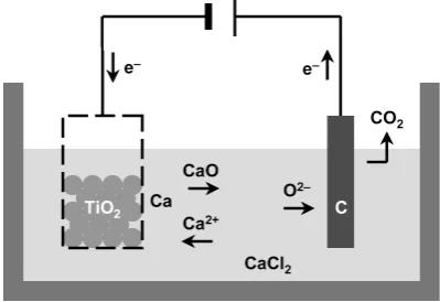
Ono and Suzuki developed the OS process6). In this, TiO 2, typically in the form of granules, is placed inside a wire mesh container and this arrangement is positioned inside a CaCl2
melt. The container is made the cathode versus a carbon an-ode, such that Ca is deposited electrolytically at the cathode and then reduces chemically the TiO2 to Ti. It is assumed that the CaO by-product dissolves in the CaCl2 melt, so that it can be re-electrolysed to release more Ca reductant and ensure the reaction progresses. The gas evolved at the anode is car-bon dioxide, provided the CaO content in the melt is suffi-ciently high, or else it is chlorine. A schematic of the electro-lytic cell arrangement is shown in Fig. 1.
Okabe and coworkers then developed the EMR process7). By this method, the TiO2 is reduced in a mediated way, i.e., without the Ca reductant being present directly at its surface. In the process, the molten salt is electrolysed in one section of the electrolytic cell to give Ca at an auxiliary nickel cathode, while the gases released at the carbon anode are carbon diox-ide and chlorine depending on melt composition. The Ca formed dissolves into the nickel giving a liquid alloy rich in Ca. This alloy is then used in a different section of the same reactor, where the Ca in the alloy ionises to give calcium ions and the electrons move around the external circuit to the TiO2 that is then reduced to Ti. This approach involves Ca at less than unit activity which is beneficial in terms of current effi-ciency, as discussed later. The cell arrangement is shown in Fig. 2.
Research in Cambridge led to the development of a some-what different electrolytic process, now known as the FFC- Cambridge process, named after its inventors, Fray, Farthing and Chen, and the place of its invention8,9). In this process, the reduction of TiO2, typically in the shape of a disc, is brought about by polarising it cathodically in a bath of molten CaCl2 versus a carbon anode, with the applied potential con-trolled such that the Ca activity is kept below unity at the cathode and no Ca metal is deposited. Under these condi-tions, ionisation of the oxygen in the TiO2 occurs. The oxide ions are expelled into the electrolyte and transport to the car-bon anode where they are discharged and carcar-bon dioxide is evolved. The set-up is shown in Fig. 3.
The overall reaction at the cathode of an FFC cell is simply the removal of oxygen from it by displacing oxide ions (O2−)
with electrons.
TiO2+4e−=Ti+2O2− (3)
It was possible experimentally to force the cathodic reduction
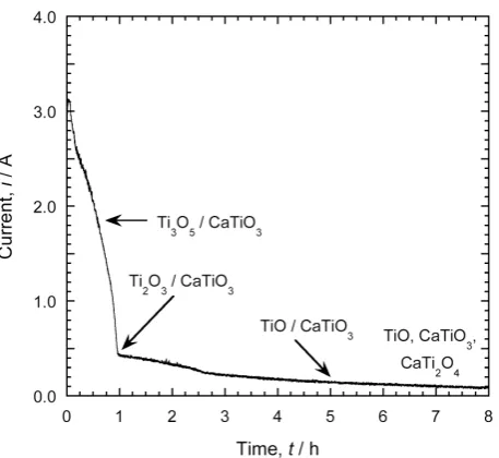
[image:2.595.326.526.615.752.2]to progress very slowly, by controlling the CaO in the CaCl2 melt at low levels of around 0.2 mol% and thereby setting up an oxide ion transport limitation across the electrolyte. In this way a current versus time curve could be recorded which, in combination with electron microscopic analyses, clearly re-veals the consecutive stages of the overall reduction24), as shown in Fig. 4.
This proves that the actual reaction sequence in the cathode is far more complex.
5TiO2+Ca2++2e−=Ti4O7+CaTiO3 (4)
4Ti4O7+Ca2++2e−=5Ti3O5+CaTiO3 (5)
3Ti3O5+Ca2++2e−=4Ti2O3+CaTiO3 (6)
2Ti2O3+Ca2++2e−=3TiO+CaTiO3 (7)
CaTiO3+TiO=CaTi2O4 (8)
CaTi2O4+2e−=2TiO+Ca2++2O2− (9)
TiO+2e−=Ti+O2− (10)
It is interesting to realise that no actual removal of oxygen from the cathode takes place in the first steps of the overall reaction, just a rearrangement of solid phases.
Along with the changes in phase composition, there are also considerable changes in the microstructure24,25), as seen in Fig. 5. These can affect the mechanical stability of the sol-id oxsol-ide body being reduced, especially at the CaTi2O4 stage where coarse elongated crystals are present that render the solid fragile.
The FFC-Cambridge process is a generic approach in that most of the oxides of the elements in the periodic table can be reduced provided these are less stable than CaO. Consequent-ly, over the last one and a half decades the reductions of a whole range of oxides to the respective metals have been re-ported in the literature. Interestingly, in most cases the reduc-tions seem to follow roughly similar paths as outlined above for TiO2, with a significant number of phases formed and de-composed intermittently. Detailed investigations revealing the reaction paths have been published for instance for the reductions of niobium oxide26), chromium oxide27), zirconi-Fig. 2 Schematic of the electrolytic cell used in the EMR process. The
set-up consists of two parts operated alternately. On the right hand side, cal-cium is formed and dissolved into nickel. On the left hand side, the ca-thodic reduction of titanium dioxide occurs through electrons travelling from the alloy along the outer circle while calcium ions are being released from the alloy into the electrolyte.
Fig. 3 Schematic of the electrolytic cell used in the FFC-Cambridge pro-cess. The cathodic reduction of titanium dioxide occurs through oxygen ionisation.
Fig. 4 Current versus time curve of an FFC reduction of titanium dioxide performed under conditions that impose a slow reaction24).
Fig. 5 Scanning electron micrographs illustrating the microstructural evo-lution of an FFC reduction of titanium dioxide performed under condi-tions that impose a slow reaction24). The stages shown are (a) TiO
[image:3.595.314.543.66.276.2] [image:3.595.68.272.67.212.2] [image:3.595.69.271.307.448.2] [image:3.595.306.547.330.483.2]um oxide28) and tantalum oxide29).
One very important finding was that alloys and intermetal-lics can be prepared directly by reducing a mixture of metal oxides. This gives the opportunity for creation of alloys that are difficult to make using co-melting, especially in cases where the boiling point of one element in the alloy is higher than the melting point of the other element. A further advan-tage is that the alloys are synthesised at temperatures around typically 800 to 900 C and thus do not undergo significant phase changes on cooling, unlike alloys prepared in the mol-ten state30–46). Rather surprisingly, low oxygen Ti alloys have been produced directly from synthetic rutile and processed by conventional and novel consolidation techniques such as iso-static pressing and 3D printing. The FFC-Cambridge process is currently being commercialised by Metalysis Ltd47).
One complication in the FFC-Cambridge process, and in-deed in all methods relying on the cathodic reduction of TiO2 in CaCl2 melts, is that Ca metal is soluble in molten CaCl2. Consequently, the activity of Ca created at any given cathodic potential leads to an amount of Ca dissolved in the melt. This imparts a degree of electronic conduction in the melt and thereby lowers current efficiency of the reduction process. As this effect increases substantially with more cathodic poten-tials, it is important not to have too high a potential at the cathode. This cannot be avoided completely in the reduction of TiO2 due to its high stability and very large current effi-ciencies cannot be reached. However, this is less of a problem for oxides that are less stable than TiO2. A further complica-tion in processes involving CaCl2 arises when a carbon mate-rial is used as the anode, as discussed later.
Quebec Iron & Titanium Inc. (QIT) have developed a vari-ation on the FFC-Cambridge process. In this, the metal oxide to be reduced and the metal produced are both in their liquid states. The oxide is typically a Ti based slag, which is placed in between a pool of a molten calcium fluoride based salt and a layer of molten Ti product, and carbon is used as the an-ode48).
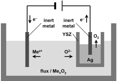
[image:4.595.326.527.70.209.2]Another method based on the cathodic reduction of metal oxides is the SOM process, as advanced by Pal and coworkers for a range of metals10–13) including Ti14). In this process, the metal oxide is dissolved in a fluoride flux, often a eutectic mixture of calcium fluoride and magnesium fluoride, and is reduced at and deposited onto a solid cathode. Alternatively, oxides that cannot be dissolved in a flux can be reduced in the form of solid bodies using cathode designs more similar to those in the OS process or the FFC-Cambridge process. The oxide ions released during the reduction dissolve in the mol-ten salt electrolyte, transfer into the solid oxide ion conduct-ing electrolyte based upon stabilised zirconia, and emerge on the opposite side of the ceramic membrane. There the oxide ions are oxidised and evolved as molecular oxygen on a pool of oxygen saturated molten silver serving as the anode. A concern might be that the Ti product is likely to be in equilib-rium with the oxygen in the electrolytes, thus preventing very low oxygen contents from being established in it. The SOM process is being commercialised by Infinium Inc. in Massa-chusetts49). A schematic of the cell arrangement is shown in Fig. 6.
A further method is the MOE process, as currently devel-oped in the Sadoway group15–17). This process starts from the
pure oxide, which is melted and electrolysed, without the use of any solvent, inside a very high temperature electrolytical cell. This approach has been successfully demonstrated for the formation of molten iron metal from molten iron oxide. It is, however, difficult to see how this could work for Ti, as this would be in contact with a molten phase containing oxygen. The MOE process is being commercialised by Boston Elec-trometallurgical Corporation50).
3. Anodic Reactions Involving the Evolution of Oxygen
A major complication in the FFC-Cambridge process, and in all other processes using the cathodic reduction in a CaCl2 melt in conjunction with a carbon anode, is caused by the anodic reaction that yields carbon dioxide (CO2).
C+2O2−=CO2+4e− (11)
The issue is that, unlike with the cryolite melt in the Hall- Héroult process, there is significant solubility of CO2 in the CaCl2 melt. Due to the presence of oxide ions in the electro-lyte it is likely that the CO2 occurs as carbonate ions (CO32−). These can diffuse to the cathode where they are reduced such that carbon is deposited and oxide ions are released.
CO2+O2−=CO32− (12)
CO32−+4e−=C+3O2− (13)
These reactions can continue for as long as CO2 is evolved at the anode, causing continuous carbon transfer through the electrolyte and carbon deposition at the cathode27,51).
An alternative reaction path might involve reducing the dissolved CO2 gas or CO32− ions with Ca that is also generat-ed at the cathode.
CO2+2Ca=C+2CaO (14)
CO32−+2Ca=C+2CaO+O2− (15) Again, the net result is the creation of carbon at the cathode from CO2 from the anode.
sions or by chemically reacting with the metal to form car-bides. Moreover the CO2 or CO32− reduction reactions cause parasitic currents through the electrolyte and thus lower cur-rent efficiency of the overall process. Interestingly, the carbon deposits formed via cathodic decomposition of CO32− ions are known to be of nanosized particles and tubes and may even find applications in high technology products52–57).
Due to these problems an inert, i.e., oxygen evolving, an-ode is needed with materials properties such as sufficient me-chanical and thermal stability, high electronic conductivity, resistance to attack by the electrolyte and oxygen, as well as electrochemical stability. This is a very demanding set of cri-teria that have never been met in the aluminium industry. However, CaCl2 should be less corrosive than cryolite, so the task might be simpler.
Doped tin oxide (SnO2) was considered a possible material for use as an inert anode. SnO2, doped with antimony oxide and copper oxide to enhance mechanical strength and elec-tronic conductivity, is used successfully in the glass industry as an electrode under conditions of alternating current in CaO containing glasses. In the CaCl2 melt as used in the FFC-Cam-bridge process, doped SnO2 was found to function satisfacto-rily as an anode for about 24 h, but then its performance dete-riorated because a layer of insulating calcium stannate gradu-ally built up around it and fingradu-ally halted the reaction58,59).
Calcium titanate (CaTiO3) was considered a further possi-bility. CaTiO3 had been found to form a thin layer around carbon anodes under certain experimental conditions in an FFC cell, indicating its stability in CaCl2 melts51). Pure CaTiO3 is a poor electronic conductor but suitable doping can enhance its conductivity. Adding oxides with a lower valency such as iron oxide (Fe2O3) only results in a minor increase in electronic conductivity60). However, incorporating highly electronically conducting calcium ruthenate (CaRuO3) was considered a better option, as this would bring in excess elec-trons. CaRuO3 has an identical crystal structure to CaTiO3 and both can form a complete range of solid solutions61). Fur-thermore, the electronic conductivity of these solid solutions increases with temperature so that at around 800 to 900 C it is more than sufficient for use as an anode62). Solid solutions of this type did indeed perform very well in a laboratory FFC cell, surviving trials of 150 h with minute wear rates63).
In the SOM process, the oxide ions in the CaCl2 melt, in-stead of being discharged immediately, are allowed to diffuse through a stabilised zirconia solid oxide ion conducting elec-trolyte10–14). The oxide ions are then discharged at an anode of molten silver, which has no stable oxide at elevated tem-peratures, and molecular oxygen is evolved. The possible dif-ficulties with this approach are the mechanical and electro-chemical stability of the ceramic membrane over extended periods of time and the scaling up from the laboratory to the industrial level.
In the oxide melts of the MOE process, two types of inert anodes have been tried, iridium metal15,16) and chromium al-loys17). Iridium can be used as an anode at elevated tempera-tures without the detrimental formation of insulating or vola-tile oxides because iridium oxide is unstable above about 1100 C. However, it is very costly which probably precludes it from general metallurgical use. Chromium alloys appear to be stable under anodic conditions for long times, probably
offering the best option for oxide melts at present. Unfortu-nately however, they do not appear to be suitable for CaCl2 melts as no stable protective film forms64).
4. Combination of Electrowinning and Electrorefining
There have been numerous attempts in the past to electro-win Ti from chloride melts, but no such process is viable due to the expensive high purity TiCl4 feedstock needed and the low current efficiency achieved. However, electrowinning of Ti from oxide feedstock would appear attractive, given that an examination of the cost of TiO2 as a function of impurities shows that TiO2 containing 10% of impurities is about an or-der of magnitude cheaper than TiO2 of 99.99% purity, and this may offset the cost caused by low current efficiency.
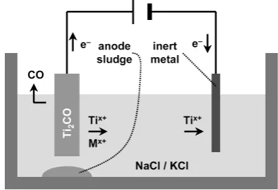
Earlier work in industry and academia had shown that pro-cesses using an electronically conducting Ti oxycarbide an-ode might be feasible65–75). Oxycarbide of approximate com-position Ti2CO can readily be prepared by reacting TiO2 with carbon at elevated temperatures in inert atmosphere, and then be used as the anode in a high temperature electrolytic cell with a molten chloride electrolyte. The Chinuka process, de-veloped in Cambridge along with an industrial partner, uses this approach, with low purity oxide as the feedstock and an inexpensive mixture of molten sodium chloride and potassi-um chloride as the electrolyte, in such a way that it combines electrowinning with electrorefining in the same cell18).
In the Chinuka process there is a sequence of ionisation reactions at the anode, in which elements such as calcium, magnesium and aluminium ionise into the molten salt along with the Ti, whereas elements such as silicon, chromium and iron are left behind forming an anode sludge. The driving force of the anodic reaction is enhanced by the concurrent release of carbon oxide gas. At the cathode, Ti deposits in preference to magnesium and calcium that build up in the melt, while the aluminium is removed as a volatile chloride. Current efficiency is relatively high as the valence state of the Ti in solution is between Ti3+ and Ti2+, instead of Ti4+ as found in processes using TiCl4. This largely suppresses back reactions with the Ti deposited and is a consequence of the reducing conditions in the preparation of the oxycarbide. The cell arrangement is shown in Fig. 7.
Discussions are ongoing with prospective partners from
[image:5.595.324.526.614.752.2]around the world to commercialise the Chinuka process. There is also considerable interest from the nuclear industry as the process would reduce the number of steps in treating used oxide fuel rods.
5. Other Processes
At the recent 13th World Conference on Titanium, other advances were mentioned but not described in detail5). These included an electrochemical process that produces Ti by a se-ries of layered membranes by Case Western Reserve Univer-sity, two processes that avoid the cyclical formation of unde-sired Ti ions by iMetalx Group and MER Corporation, and an electrochemical process for the production of high quality Ti powder by TIMET.
6. Removal of Alpha Case, Preventing Oxidation, and Welding in Air without Inert Gas
One of the problems with the fabrication and usage of Ti components is the formation of the alpha case when Ti is ex-posed to an oxidising environment, especially at elevated temperatures. The alpha case is a hard oxygen enriched me-tallic scale that grows due to the high solubility of oxygen in Ti giving rise to a solid solution of oxygen in Ti. The alpha case often needs to be removed from Ti components because it has inferior mechanical and fatigue properties compared with the pure metal. Conventionally, this is done either chem-ically by dissolving the scale in hydrofluoric acid based leachant or mechanically by grinding it away. The disadvan-tages of these treatments are in both cases that there is a slight change in the dimensions of the Ti component and that there are disposal problems of either highly corrosive acids or fine particles. A more suitable treatment would possibly be to re-generate Ti components electrochemically, i.e., by selectively removing the oxygen from the scale. The FFC-Cambridge process is well placed to achieve this. As with the reduction of solid oxides, the Ti artefact is made the cathode in a bath of CaCl2 and the oxygen is removed from its surface under a modest cathodic potential without Ca deposition. Proof of concept for this approach was published in 200119).
A better solution would be to prevent the oxidation of Ti components during processing or use in the first place. One way of achieving this is by applying a cover of flux, but com-mercial fluxes frequently contain fluoroborates and boric acid which should be reduced by Ti, thus bringing oxygen into it. Another way is to use an inert gas such as helium, which is expensive, or argon, which is cheaper but less efficient. Ca-thodic protection is a method that is applied extensively at ambient temperatures to preclude corrosion of predominantly steel constructions such as ships, pipelines and vessels. This is accomplished by having a moderate cathodic potential at the metal component to be protected versus a suitable anode. Recently this technique has been investigated as a means of prevention of oxidation of Ti76). Protection was successfully achieved by applying a cathodic potential to Ti metal cruci-bles, partially filled with molten CaCl2, against an anode of doped SnO2 or iridium, as the protected area did not undergo any noticeable oxidation or corrosion after harsh heat treat-ment. The technique was also successfully applied to protect
a molten Ti alloy.
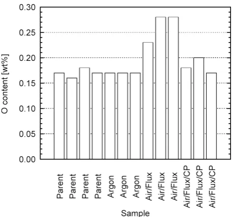
A considerably more exciting application is to use cathodic protection whilst welding Ti components in air. This would be instead of welding under a protective atmosphere provided by either a gas blanket or a gas filled cubicle, as done in estab-lished welding technologies. The concept was proven by spot welding Ti-6Al-4V alloy plates with an ytterbium fibre laser under a calcium fluoride based flux cover and polarising the Ti alloy against an iridium inert anode touching the salt flux. Analysing the Ti alloy after the welding experiments, it was found that the oxygen contents of the weld metal were very close to that in the starting material, while the nitrogen con-tents had increased very slightly77). The results for oxygen as determined by the hot extraction method are shown in Fig. 8.
7. Conclusions
In the past twenty years several new molten salt electro-chemical methods for the cathodic reduction of titanium di-oxide have been investigated. A few of these, the OS, FFC- Cambridge, SOM and MOE processes, have managed to gain further funding to advance work to a larger scale and market industrial grade quantities.
In all these processes one of the challenges has been to find an inert anode to avoid carbon dioxide generation and thus overcome the problem of carbon dioxide dissolution in some of the electrolytes. Progress has been made in this direction for both chloride and oxide melts, but research needs to con-tinue.
The Chinuka process, based on the electrowinning of tita-nium from titatita-nium oxycarbide anodes in molten chlorides, has been advanced aiming to enable the use of cheap impure titanium oxide feedstock. The process is now ready for scal-ing up.
[image:6.595.312.541.67.281.2]has been shown to be effective in removing the alpha case, stopping oxidation, and allowing the welding of titanium in air without the need of a protective gas.
REFERENCES
1) W.J. Kroll: Trans. Am. Inst. Min. Metall. Eng. 215 (1959) 546–553. 2) F. Habashi (ed.): Handbook of Extractive Metallurgy, vol. 2, (Wiley-
VCH, Weinheim, Germany, 1997) Chapter 22 Titanium, pp. 1129– 1180.
3) D.J. Fray: Int. Mater. Rev. 53 (2008) 317–325.
4) D.S. van Vuuren: J. S. Afr. Inst. Min. Metall. 109 (2009) 455–461. 5) M.A. Imam: JOM 68 (2016) 2492–2501.
6) R.O. Suzuki, K. Teranuma and K. Ono: Metall. Mater. Trans., B 34 (2003) 287–295.
7) I. Park, T. Abiko and T.H. Okabe: J. Phys. Chem. Solids 66 (2005) 410–413.
8) D.J. Fray, T.W. Farthing and Z. Chen: WO Patent 9964638 (1999). 9) G.Z. Chen, D.J. Fray and T.W. Farthing: Nature 407 (2000) 361–364. 10) U.B. Pal, D.E. Woolley and G.B. Kenney: JOM 53 (2001) 32–35. 11) A. Krishnan, X.G. Lu and U.B. Pal: Scand. J. Metall. 34 (2005) 293–
301.
12) A. Krishnan, X.G. Lu and U.B. Pal: Metall. Mater. Trans., B 36 (2005) 463–473.
13) U.B. Pal and A.C. Powell: JOM 59 (2007) 44–49.
14) M. Suput, R. DeLucas, S. Pati, G. Ye, U. Pal and A.C. Powell: Min. Proc. Extract. Metall. (Trans. Inst. Min. Metall. C) 117 (2008) 118– 122.
15) D.H. Wang, A.J. Gmitter and D.R. Sadoway: J. Electrochem. Soc. 158 (2011) E51–E54.
16) H. Kim, J. Paramore, A. Allanore and D.R. Sadoway: J. Electrochem. Soc. 158 (2011) E101–E105.
17) A. Allanore, L. Yin and D.R. Sadoway: Nature 497 (2013) 353–356. 18) S.Q. Jiao and D.J. Fray: US Patent 20160010232 A1 (2016).
19) G.Z. Chen, D.J. Fray and T.W. Farthing: Metall. Mater. Trans., B 32 (2001) 1041–1052.
20) M.V. Ginatta: US Patent 6074545 A (2000).
21) M.V. Ginatta: Ti-2003 Science and Technology, Proc. 10th World Conf. on Titanium, Hamburg, Germany, 2003, ed. by G. Lütjering and J. Al-brecht, (Wiley-VCH, Weinheim, 2004) pp. 237–244.
22) A. Roine: HSC Chemistry, Version 6.0, (Outokumpu Research Oy, Pori, Finland, 2006).
23) T.H. Okabe, M. Nakamura, T. Oishi and K. Ono: Metall. Trans. B 24 (1993) 449–455.
24) C. Schwandt and D.J. Fray: Electrochim. Acta 51 (2005) 66–76. 25) D.T.L. Alexander, C. Schwandt and D.J. Fray: Acta Mater. 54 (2006)
2933–2944.
26) X.Y. Yan and D.J. Fray: J. Electrochem. Soc. 152 (2005) E308–E318. 27) C. Schwandt and D.J. Fray: Z. Naturforsch. A 62 (2007) 655–670. 28) K.S. Mohandas and D.J. Fray: Metall. Mater. Trans., B 40 (2009) 685–
699.
29) R.P. Barnett and D.J. Fray: J. Mater. Sci. 49 (2014) 4148–4160. 30) X.Y. Yan and D.J. Fray: Adv. Funct. Mater. 15 (2005) 1757–1761. 31) X.Y. Yan and D.J. Fray: J. Alloy. Compd. 486 (2009) 154–161. 32) A.M. Abdelkader and D.J. Fray: Electrochim. Acta 55 (2010) 2924–
2931.
33) D.J.S. Hyslop, A.M. Abdelkader, A. Cox and D.J. Fray: J. Electrochem. Soc. 157 (2010) E111–E115.
34) Q. Xu, C. Schwandt and D.J. Fray: Adv. Mater. Res. 160–162 (2011) 1131–1135.
35) Y. Zhu, M. Ma, D.H. Wang, K. Jiang, X.H. Hu, X.B. Jin and G.Z. Chen: Chin. Sci. Bull. 51 (2006) 2535–2540.
36) Y. Zhu, D.H. Wang, M. Ma, X.H. Hu, X.B. Jin and G.Z. Chen: Chem. Commun. 24 (2007) 2515–2517.
37) J.J. Peng, Y. Zhu, D.H. Wang, X.B. Jin and G.Z. Chen: J. Mater. Chem. 19 (2009) 2803–2809.
38) K. Dring, R. Bhagat, M. Jackson, R. Dashwood and D. Inman: J. Alloy.
Compd. 419 (2006) 103–109.
39) R. Bhagat, M. Jackson, D. Inman and R. Dashwood: J. Electrochem. Soc. 155 (2008) E63–E69.
40) B. Jackson, M. Jackson, D. Dye, D. Inman and R. Dashwood: J. Elec-trochem. Soc. 155 (2008) E171–E177.
41) R. Bhagat, M. Jackson, D. Inman and R. Dashwood: J. Electrochem. Soc. 156 (2009) E1–E7.
42) B.X. Wang, R. Bhagat, X.Z. Lan and R.J. Dashwood: J. Electrochem. Soc. 158 (2011) D595–D602.
43) X.J. Liao, H.W. Xie, Y.C. Zhai and Y. Zhang: J. Mater. Sci. Technol. 25 (2009) 717–720.
44) X.L. Zou, X.G. Lu, C.H. Li and Z.F. Zhou: Electrochim. Acta 55 (2010) 5173–5179.
45) M. Anik, A.B. Aybar, N.B. Hatirnaz and D. Özdemir: J. Electrochem. Soc. 162 (2015) A1080–A1084.
46) K.H. Chen, Y.X. Hua, C.Y. Xu, Q.B. Zhang, C.C. Qi and Y.F. Jie: Ce-ram. Int. A 41 (2015) 11428–11435.
47) Metalysis: http://www.metalysis.com (accessed 2016-09-27). 48) F. Cardarelli: US Patent 20040194574 A1 (2004).
49) Infinium: http://www.infiniummetals.com (accessed 2016-09-27). 50) Boston Electrometallurgical Corporation: http://www.
bostonelectromet.com (accessed 2016-09-27).
51) C. Schwandt, D.T.L. Alexander and D.J. Fray: Electrochim. Acta 54 (2009) 3819–3829.
52) I.A. Novoselova, N.F. Oliinyk, S.V. Volkov, A.A. Konchits, I.B. Yan-chuk, V.S. Yefanov, S.P. Kolesnik and M.V. Karpets: Physica E 40 (2008) 2231–2237.
53) H.Y. Yin, X.H. Mao, D.Y. Tang, W. Xiao, L.R. Xing, H. Zhu, D.H. Wang and D.R. Sadoway: Energy Environ. Sci. 6 (2013) 1538–1545. 54) H.V. Ijije, C.G. Sun and G.Z. Chen: Carbon 73 (2014) 163–174. 55) J.W. Ren, J. Lau, M. Lefler and S. Licht: J. Phys. Chem. C 119 (2015)
23342–23349.
56) J.W. Ren, F.-F. Li, J. Lau, L. Gonzalez-Urbina and S. Licht: Nano Lett. 15 (2015) 6142–6148.
57) J.B. Ge, L.W. Hu, Y. Song and S.Q. Jiao: Faraday Discuss. 190 (2016) 259–268.
58) R. Barnett, K.T. Kilby and D.J. Fray: Metall. Mater. Trans., B 40 (2009) 150–157.
59) K.T. Kilby, S.Q. Jiao and D.J. Fray: Electrochim. Acta 55 (2010) 7126– 7133.
60) H. Iwahara, T. Esaka and T. Mangahara: J. Appl. Electrochem. 18 (1988) 173–177.
61) T. He and R.J. Cava: Phys. Rev. B 63 (2001) article number 172403. 62) S.Q. Jiao, K.N.P. Kumar, K.T. Kilby and D.J. Fray: Mater. Res. Bull. 44
(2009) 1738–1742.
63) S.Q. Jiao and D.J. Fray: Metall. Mater. Trans., B 41 (2010) 74–79. 64) C. Schwandt: unpublished results.
65) E. Wainer: US Patent 2722509 A (1955).
66) J.C. Withers and R.O. Loutfy: US Patent 20050166706 A1 (2005). 67) J.C. Withers, R.O. Loutfy and J.P. Laughlin: Mater. Technol. 22 (2007)
66–70.
68) J. Withers, J. Laughlin, Y. Elkadi, J. DeSilva and R. Loutfy: Key Eng. Mater. 436 (2010) 55–60.
69) J. Withers, J. Laughlin, Y. Elkadi, J. DeSilva and R. Loutfy: Key Eng. Mater. 436 (2010) 61–74.
70) S.Q. Jiao and H.M. Zhu: J. Mater. Res. 21 (2006) 2172–2175. 71) S.Q. Jiao and H.M. Zhu: J. Alloy. Compd. 438 (2007) 243–246. 72) S.Q. Jiao, X.H. Ning, K. Huang and H.M. Zhu: Pure Appl. Chem. 82
(2010) 1691–1699.
73) O.S. Kjos, G.M. Haarberg and A.M. Martinez: ECS Trans. 16 (2009) 229–237.
74) A.M. Martinez, K.S. Osen, E. Skybakmoen, O.S. Kjos, G.M. Haarberg and K. Dring: Key Eng. Mater. 436 (2010) 41–53.
75) O.S. Kjos, G.M. Haarberg and A.M. Martinez: Key Eng. Mater. 436 (2010) 93–101.
76) C. Schwandt and D.J. Fray: Metall. Mater. Trans., B 45 (2014) 2145– 2152.