Difference in Bioactivity, Initial Cell Attachment and Cell Morphology Observed
on the Surface of Hydroxyapatite Ceramics with Controlled Orientation
Takeshi Hagio
1;*1, Tomohiko Tanase
1;*2, Jun Akiyama
1;*3,
Masanori Umino
1;*4, Kazuhiko Iwai
1and Shigeo Asai
21Department of Materials, Physics and Energy Engineering, Nagoya University, Nagoya 464-8603, Japan 2Innovation Plaza Tokai Japan Science and Technology Agency, Nagoya 457-0063, Japan
Hydroxyapatite ceramics has been demonstrated to be an appropriate material for biomedical applications owing to its bioactivity and high biocompatibility. It has an anisotropic crystal structure that belongs to the hexagonal system, and two types of crystal planes mainly appear on its crystal, which are a-plane and c-plane. Since these two crystal planes are very different in atomic elements, numbers and arrangements, they exhibit different nature (anisotropy). For this reason, it is said that crystal orientation might be intensifying its bioactivity and biocompatibility. However, the differences in biological features on these two crystal planes are not fully clarified yet. In this study, we have conducted an assessment to reveal anisotropic biological features of hydroxyapatite by using hydroxyapatite ceramics with controlled orientation fabricated by slip casting under a magnetic field. Tanaseet al.have recently reported the difference in bioactivity on the two crystal planes by immersing crystal oriented hydroxyapatite ceramics into the simulated body fluid and found that c-plane oriented hydroxyapatite ceramics formed a precipitate layer earlier and thicker on its surface compared to a-plane oriented one. We first carried out Welch’s t-test on the difference in the thickness of the precipitate layer, reported previously to reveal the difference in bioactivity. Secondly, we conducted an osteoblast culture experiment on hydroxyapatite ceramics with controlled orientation to reveal the difference in initial cell attachment and cell morphology on the two crystal planes of hydroxyapatite using optical microscope observations. In the former case, the results of the Welch’s t-test indicated that the thickness of the precipitate significantly differed on each crystal oriented hydroxyapatite ceramics (P<0:05). In the latter case, initial cell attachment seemed to be better on the a-plane oriented hydroxyapatite ceramics and also the morphology of the osteoblasts seemed to be rounded on the a-plane oriented hydroxyapatite ceramics compared to the c-plane oriented one. [doi:10.2320/matertrans.MBW200836]
(Received October 29, 2008; Accepted January 23, 2009; Published March 25, 2009)
Keywords: hydroxyapatite, anisotropic biological features, crystal orientation, bioactivity, initial cell attachment, cell morphology
1. Introduction
Hydroxyapatite (HAp; Ca10(PO4)6(OH)2) is the major inorganic component of human hard tissues,1–6) and it is a bioactive and biocompatible material widely utilized in biomedical applications.1–8) It has an anisotropic crystal structure that belongs to the hexagonal system, and two types of crystal planes mainly appear on its crystal, which are a-plane and c-a-plane. Since these two crystal a-planes are very different in atomic elements, numbers, and arrangements, they exhibit different nature (anisotropy).1)For example, the c-plane of HAp is mainly occupied by negatively charged phosphoric acid groups that adsorbs the amino acids in proteins, while the a-plane of HAp is mainly occupied by positively charged calcium ions that adsorbs the carboxyl groups in proteins.9,10)For this reason, it is believed that the bioactivity and biocompatibility of polycrystalline HAp might be intensified by crystal orientation. In fact, the human hard tissues are composed of HAp nanocrystals that form a self-organized structure exhibiting crystal orientation in a particular direction.11)In the human long bone, for instance, the c-plane of HAp is oriented in the direction perpendicular to the longitudinal axis of the collagen fibril and the direction of the critical load.11) The crystal orientation enhances the anisotropic properties of HAp; thus, the natural hard tissues
must be selectively utilizing the anisotropic properties that depend on the two typical crystal planes of HAp. However, the difference in the biological features of each crystal plane of HAp has not been fully clarified yet.
On the other hand, it has been reported that the crystal orientation in materials can be controlled by applying an external magnetic field.12–14) Owing to the recent develop-ments in superconducting technology, controlling the crystal orientation using a magnetic field has been extended to non-magnetic substances including HAp.2–5,15,16)
In this study, we have carried out an assessment to reveal the anisotropic biological features of HAp by using HAp ceramics with controlled orientation fabricated by slip casting under a magnetic field. Tanaseet al.6)have recently reported the difference in the bioactivity of the two crystal planes by immersing crystal oriented HAp ceramics into the simulated body fluid, and they found that the precipitate layer formed earlier and thicker on the surface of c-plane oriented HAp ceramics than on the surface of a-plane oriented one. First, we carried out Welch’s two-tailed t-test on the difference in the thickness of the precipitate layer; by further analyzing the precipitate layers formed on samples used by Tanase et al. and by analyzing those formed on similar samples used in a duplicate experiment, to clarify the difference in bioactivity. Second, we con-ducted an osteoblast culture experiment on the HAp ceramics with controlled orientation to reveal the difference in the initial cell attachment and cell morphology on the two crystal planes of HAp by means of optical microscope observations.
*1Graduate Student, Nagoya University
*2Graduate Student, Nagoya University. Present address: TOHO Gas Co.,
LTD, Nagoya 456-8511, Japan
*3Graduate Student, Nagoya University. Present address: Institute for
Molecular Science, Okazaki 444-8585, Japan
*4Undergraduate Student, Nagoya University
2. Experimental Procedure
2.1 Fabrication of HAp ceramics with controlled ori-entation
Commercial powder of HAp (Taihei Chemical Industrial Co. LTD., HAp-200) was dispersed and suspended in ion-exchanged water using a polymeric dispersing agent. The particle size distribution of the initial HAp powder used in
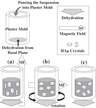
this study, measured using a laser scattering particle size distribution analyzer (HORIBA, LA-920), is shown in Fig. 1. The particles had a modal and median diameter of about 10mmand more than 90% of the particles had a diameter between 4–30mm. The prepared suspension was ground in an agate mortar using an automatic milling machine (Nitto Kagaku Co. Ltd., Type ANM1000) to disintegrate the aggregated particles.2,3) A well-dispersed slurry of the disaggregated HAp particles was obtained by milling the suspension for more than 14.4 ks (4 h). The slurry was then poured into plaster molds and slip cast inside the bore of a superconducting magnet generating a 10 T magnetic field in order to form HAp green compacts with controlled orienta-tion. In addition, slip casting was carried out in the absence of a magnetic field to prepare a green compact without controlled orientation as a control. The slip casting con-ditions are summarized in Fig. 2.
The crystal orientation of HAp under a magnetic field is expressed in terms of the magnetization energy U by the following equation.5)
U¼ 1
20B 2V
ð1Þ
Here,0,,B, andV are magnetic permeability in vacuum, magnetic susceptibility of HAp in the direction parallel to that of the external magnetic field, external magnetic flux
1 10 102
Particle Size / µm
10
0
Frequency / %
4 µm 30 µm Modal diameter
9.44 µm
Median diameter 10.07 µm
0 100
Cumulative % Passing / %
: Area of 90 % of the total
: Cumulative % Passing : Frequency
Fig. 1 Particle size distribution of HAp powder used in this study.
MF
(b)
rotation
Pouring the Suspension
into Plaster Mold
Dehydration from
Basal Plane
Plaster Mold
(c)
MF
(a)
Dehydration
Magnetic Field
MFHAp Crystals
[image:2.595.56.283.72.245.2] [image:2.595.144.455.408.758.2]density, and volume of the HAp crystal, respectively. Since the magnetic susceptibility perpendicular to the c-axis,?,
and that parallel to the c-axis, ==, are considered to be different (?6¼==) in hexagonal crystals, the HAp crystal rotates to minimize its energy. The magnetic susceptibility of HAp is anticipated to be?> ==(U?<U==),5)so HAp with a-plane orientation can be fabricated under a static magnetic field2–4,16)and HAp with c-plane orientation can be fabricated under a rotating magnetic field.5,15–17)
The fabricated green compacts were completely dried in the absence of a magnetic field and were subsequently sintered in an electric furnace. Their crystal orientation was then observed by X-ray diffraction (XRD; Rigaku Corp., cat. no. 2035G403) using Cu-K radiation, after their surfaces were polished with an abrasive paper of grade #2000.
2.2 SBF immersion test using crystal oriented HAp ceramics
The fabricated HAp ceramics- the a- and c-plane oriented HAp ceramics and the control- were immersed in a conven-tional simulated body fluid (c-SBF).18) After 43.2, 86.4, 172.8, and 259.2 ks (12, 24, 48, and 72 h) of immersion, the cross-section of HAp ceramics were observed using the scanning electron microscope (SEM: Keyence Corp., VE-7800). The thickness of the precipitate layer formed on the surface of the HAp ceramics was then measured. The measured values were assessed by conducting a statistical analysis called Welch’s two-tailed t-test to clarify the dif-ference in the bioactivity of the HAp ceramics. The thickness was measured at two randomly selected points from 8–12 SEM images collectively obtained from the further analyzed samples used by Tanase et al. and from the similarly characterized samples used in a duplicate experiment.
2.3 Osteoblast culture experiments using crystal orient-ed HAp ceramics
The osteoblastic cell line MC3T3-E1 (Riken BioResource Center, RCB1126) was used in this study. The cells were incubated in a petri dish with culture medium- -minimum essential medium (-MEM; Sigma) supplemented with 10% heat-inactivated fetal bovine serum (FBS; Sigma) and a small amount of penicillin-streptomycin solution (Sigma). The petri dish was placed in an incubator providing fully humidified atmosphere kept at 310 K with 5% carbon dioxide (CO2). The culture medium was changed every 2–3 days and the cells were passaged just before they attained a confluent density.
For the culture experiments, the cells were collected in a fresh medium after being washed with phosphate buffered saline (PBS; Sigma) and detached with 0.25% trypsin-EDTA solution (Sigma). The cells were then seeded on to the fabricated HAp ceramics placed in a 48-well culture micro-plate at a cell density of 26:5104 cells/well. After incubating for a certain time period, the cells were washed twice with PBS and fixed using ethanol. The cells were then stained using Giemsa stain solution to enable observation. The initial cell attachment efficiency was assessed after incubation for 10.8 ks (3 h) and the cell morphology was observed after incubation for 24 h by means of an optical microscope.
3. Results and Discussions
3.1 Characterization of the fabricated HAp ceramics
All of the fabricated HAp ceramics were discoid in shape with diameters of about 10 mm. Characteristics of the samples used for the SBF immersion test are described in Ref. 6).
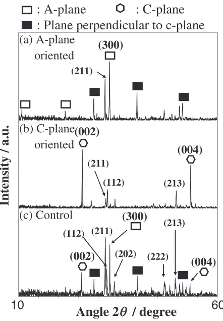
The XRD patterns of the three HAp ceramics used for the osteoblast culture experiments are shown in Fig. 3. The XRD pattern of the control (Fig. 3(c)) showed reflections corre-sponding to various crystal planes and the major intensified peaks were similar to those in the reference data (HAp: JCPDS #73-0293), indicating that the control had a random orientation. The XRD pattern of HAp ceramics fabricated by slip casting under a static magnetic field showed intense reflections corresponding to (300); the a-plane, and planes perpendicular to the c-plane; planes relatively close to the a-plane (with inclination angle smaller than 20 degrees), while the reflections corresponding to the c-plane could be barely observed (Fig. 3(a)). In contrast, the XRD patterns of HAp ceramics fabricated by slip cast under a rotating magnetic field had intense reflections corresponding to (002) and (004); the c-planes, while the reflections corresponding to other planes were significantly suppressed (Fig. 3(b)). These results indicate that a- and c-plane oriented HAp ceramics were fabricated successfully. After the XRD analysis, the three HAp ceramics were buff-polished with alumina particles of 0.3mm (Praxair Surface Technologies, Inc., alumina polishing compound) to reduce the effect of surface
Intensity / a.u.
10
60
Angle 2
θ
/ degree
(211)(112) (211)
(a) A-plane
oriented
(b) C-plane
oriented
(c) Control
: A-plane
: C-plane
: Plane perpendicular to c-plane
(213)
(213)
(300)
(300)
(002)
(004)
(002)
(004)
(222)(202) (211)
(112)
[image:3.595.317.538.72.390.2]roughness on cell attachment. Next, the ceramics were sterilized in an autoclave and subsequently irradiated by ultra violet light for at least 1.8 ks (0.5 h).
3.2 Statistical analysis of difference in thickness of precipitate layer
Figure 4 shows the average thickness of the precipitate layer, along with the 95% confidence interval, formed on the two crystal oriented HAp ceramics after being immersed in the SBF for 12, 24, 48, and 72 h. The result of Welch’s two-tailed t-test is summarized in Table 1. The results revealed that the thickness of the precipitate layer formed on the crystal oriented HAp ceramics immersed in the SBF was significant at the significant level ¼0:05, i.e., P<0:05, in every case assessed here.
Two questions arise from the obtained results. The first one is, why does the precipitate layer form earlier and is thicker on the c-plane oriented HAp ceramics than that formed on the a-plane oriented ones? The second question is, why is the 95% confidence interval wider in the case of the c-plane oriented HAp ceramics than that in the case of the a-plane oriented ones? The former question may be explained by the difference in the growth mechanism and/or that in the surface charge on the two crystal planes of HAp. The growth mechanism on the two crystal planes of HAp has been explained by Onumaet al.19–21)According to their study, the crystal growth mechanism on the a-plane is a combination of step flow mechanism and two-dimensional nucleation, while that on the c-plane is a multiple two-dimensional nucleation. Such difference in the growth mechanism may have caused the significant difference in the thickness of the precipitate layer. As for the surface charge, Tanahashi et al.22) have investigated the surface
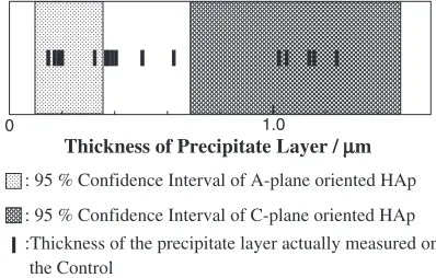
functional group dependence on apatite formation on self-assembled monolayers (SAMs) in the SBF and have reported that SAMs of alkanethiols having negatively charged groups such as phosphoric groups (-PO4H2) and carboxyl groups (-COOH) strongly induced apatite forma-tion, while the positively animo groups (-NH2) did not strongly induce apatite formation. Since the a-plane of HAp is positively charged and the c-plane is negatively charg-ed,9,10)we may anticipate that this polarization difference is another reason why the thickness of the precipitate layer formed on the two crystal oriented HAp ceramics differed. In fact, the thickness of the precipitate layer formed on the control varied over different regions, showing polygonal shapes that well resembled the shapes of individual grains observed on the etched surface of the control (see Ref. 6)). Figure 5 shows the thickness of the precipitate layer formed on the control immersed in the SBF for 72 h along with the 95% confidence interval of the a- and the c-plane oriented HAp ceramics. It can be observed that the thickness of the precipitate layer is distributed widely between the maximum value of 95% confidence interval of the c-plane oriented HAp ceramics and the minimum value of 95% confidence interval of the a-plane oriented HAp ceramics. Thus, it may be inferred that the thickness of the precipitate layer formed is dependent on the nature of individual crystal planes of HAp. The latter question may also be explained by the different growth mechanism on the two crystal planes of HAp. Since the growth mechanism on the a-plane is a combination of step flow mechanism and two-dimensional nucleation, the precipitate layer must have formed gradual-ly, meaning that perhaps the precipitate layer forms quite uniformly. Meanwhile, since the growth mechanism on the c-plane is a multiple two-dimensional nucleation, the nucleation must have taken place throughout the surface, meaning that the precipitate layer forms scabrous compared to that on the a-plane oriented one. In addition, we can say that the growth rate of the precipitate layer is much larger on the c-plane oriented HAp ceramics compared to that on the a-plane oriented one from Fig. 4. This large growth rate on the c-plane perhaps enhanced the asperity of the surface. Actually, the standard deviation of the thickness of the precipitate layer was approximately 2 times larger on the c-plane than that on the a-plane. We perhaps measured this asperity, and this may have appeared in the results as the wider confidence interval on the c-plane oriented HAp ceramics.
12
Immersing Time / h 0
1.0
Thickness of Precipitate Layer /
µ
m
: A-plane oriented
: C-plane oriented
24 48 72
[image:4.595.325.524.73.200.2]Fig. 4 Relation between the immersing time and thickness of precipitation layer with 95% confidence interval.
Table 1 Results of Welch’s two-tailed T-test on difference in thickness of precipitate layer at the significant level of¼0:05.
Immersion Time/hour
P-value/-12 0.0042 (<0:05) 24 0.0118 (<0:05) 48 0.0005 (<0:05) 72 0.0011 (<0:05)
0 1.0
Thickness of Precipitate Layer / µm
: 95 % Confidence Interval of A-plane oriented HAp
: 95 % Confidence Interval of C-plane oriented HAp :Thickness of the precipitate layer actually measured on
the Control
[image:4.595.73.273.76.225.2] [image:4.595.46.292.302.367.2]3.3 Initial cell attachment on the crystal oriented HAp ceramics
The initial cell attachment efficiency was calculated after incubating for 3 h by dividing the number density of cells observed in an image taken using the optical microscope by the number density of cells seeded into the well. The results are shown in Fig. 6. It can be observed that the initial cell attachment efficiency on the a-plane oriented HAp ceramics was higher than that on the control, while that on the c-plane oriented one was lower than that on the control. This may be a result of the difference in the absorbability of proteins of the two crystal planes of HAp. Acidic proteins are believed to be adsorbed on the a-plane, while basic proteins are believed to be on adsorbed the c-plane.9,10) In this study, perhaps, selective adsorption of bovine serum albumin (BSA; an acidic protein) in the FBS, which was added to the medium, occurred on the a-plane oriented HAp ceramics, and that might have promoted initial cell attachment. Kawachi et al.7)reported that porous HAp having a larger surface area of a-plane showed higher absorbability of albumin as compared to the isotropic HAp. Further, Bernards et al.8) reported that the biggest impact on MC3T3-E1 cell binding to HAp was found in the case of substrates with adsorbed BSA among bone sialoprotein (BSP), bone osteopontin (OPN) and BSA, and they concluded that BSA influences the adhesion and prolifer-ation of osteoblasts to HAp. However, a further investigprolifer-ation on other effects such as those of cell adhesive proteins is required.
3.4 Cell morphology
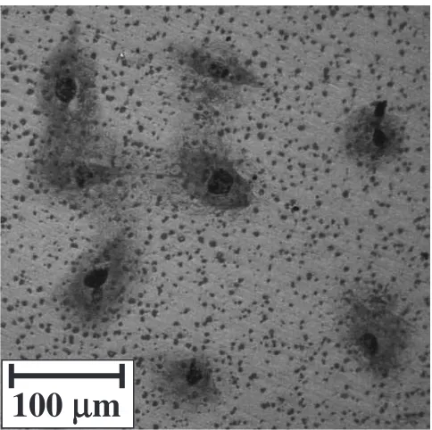
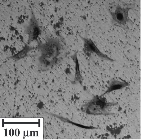
Figures 7–9 show images of the Giemsa-stained cells on the three HAp ceramics after incubating for 24 h. The cells morphology was observed from the images. It appeared that the morphology of the cells on the a-plane oriented HAp ceramics was more rounded as compared to that of the cells on the c-plane oriented ones, as shown in Figs. 7 and 8. In contrast, the cells on the c-plane oriented HAp ceramics appeared to be elongating its nueraxons, as shown in Fig. 8. Both types of cells appeared to co-existed on the control, as shown in Fig. 9, without showing distinct partiality to either. The difference in the cell morphology observed here may have been caused by the difference in step of growth after the initial cell attachment or by the affinity between cell adhesion proteins and the atoms dominating the crystal planes.
However, further investigations are required to understand this phenomenon.
4. Conclusion
In this study, we have conducted two assessments to reveal the anisotropic biological features of HAp by using crystal oriented HAp ceramics fabricated by slip casting under a magnetic field. One was Welch’s t-test conducted on the difference in the thickness of the precipitate layer formed on crystal oriented HAp ceramics immersed in SBF, as recently
:A-plane oriented
:C-plane oriented
:Control
0 1.0
Initial Cell Attachment
Efficiency /
-Fig. 6 Initial cell attachment efficiency on three substrates.
100
µ
m
Fig. 7 Image of MC3T3-E1 cells incubated for 24 h on A-plane oriented HAp ceramics.
100
µ
m
[image:5.595.306.548.70.311.2] [image:5.595.70.270.74.207.2]reported by Tanase et al., to clarify the difference in the bioactivities on the two crystal planes of HAp. The other was the cell culture experiment of MC3T3-E1 on crystal oriented HAp ceramics to reveal the difference in initial cell attach-ment and cell morphology on the two crystal planes of HAp by means of optical microscope observations. By conducting such assessments, the following results were obtained.
(1) There was significant difference in the thickness of the precipitate layer between the a-plane oriented HAp ceramics and the c-plane oriented ones (P<0:05). (2) The thickness of the precipitate layer appeared to be
dependent on the nature of individual crystal planes of HAp.
(3) The initial cell attachment efficiency of MC3T3-E1 was higher on the a-plane oriented HAp ceramics as compared to that on the c-plane oriented ones. (4) The crystal orientation of HAp appeared to affect the
cell morphology of MC3T3-E1.
Acknowledgement
This research was partially supported by Iron and Steel Institute of Japan and JSPS Asian Core Program ‘‘Construc-tion of the World Center on Electromagnetic Processing of Materials’’.
REFERENCES
1) H. Aoki: Surf. Sci.10(1989) 96–101.
2) K. Inoue, K. Sassa, Y. Yokogawa, Y. Sakka, M. Okido and S. Asai: Mater. Trans.44(2003) 1133–1137.
3) Y. Sakka, K. Takahashi, N. Mastuda and T. S. Suzuki: Mater. Trans.48
(2007) 2861–2866.
4) Y. Sakka, K. Takahashi, T. S. Suzuki, S. Ito and N. Matsuda: Mater. Sci. Eng. A475(2008) 27–33.
5) J. Akiyama, M. Hashimoto, H. Takadama, F. Nagata, Y. Yokogawa, K. Sassa, K. Iwai and S. Asai: Mater. Trans.46(2005) 203–206. 6) T. Tanase, J. Akiyama, K. Iwai and S. Asai: Mater. Trans.48(2007)
2855–2860.
7) G. Kawachi, S. Sasaki, K. Nakahara, E. H. Ishida and K. Ioku: Key Eng. Mater.309–311(2006) 935–938.
8) M. T. Bernards, C. Qin and S. Jiang: Colloid. Surf. B64(2008) 236– 247
9) T. Kawasaki: J. Chromatogr.151(1978) 95–112.
10) T. Kawasaki, S. Takahashi and K. Ikeda: Eur. J. Biochem.152(1985) 361–371.
11) T. Nakano, K. Kaibara, Y. Tabata, N. Nagata, S. Enomoto, E. Marakawa and Y. Umakoshi: Bone31(2002) 479–487.
12) H. Morikawa, K. Sassa and S. Asai: Mater. Trans. JIM 39(1998) 814–818.
13) T. Taniguchi, K. Sakka and S. Asai: Mater. Trans. JIM 41(2000) 981–984.
14) M. Tahashi, M. Ishihara, K. Sassa and S. Asai: Mater. Trans.44(2003) 285–289.
15) J. Akiyama, M. Hashimoto, H. Takadama, F. Nagata, Y. Yokogawa, K. Sassa, K. Iwai and S. Asai: Mater. Trans.46(2005) 2514–2517. 16) T. Kimura: Polymer J.35(2003) 823–843.
17) J. Akiyama, H. Asano, K. Iwai and S. Asai: J. Japan Inst. Metals71
(2007) 108–112.
18) T. Kokubo and H. Takadama: Biomaterials27(2006) 2907–2915. 19) K. Onuma, A. Ito, T. Tateishi and T. Kameyama: J. Cryst. Growth154
(1995) 118–125.
20) N. Kanzaki, K. Onuma, A. Ito, K. Teraoka, T. Tateishi and S. Tsutsumi: J. Phys. Chem. B102(1998) 6471–6476.
21) K. Onuma, N. Kanzaki, A. Ito and T. Tateishi: J. Phys. Chem. B102
(1998) 7833–7838.
22) M. Tanahashi and T. Matsuda: J. Biomed. Mater. Res. 34 (1997) 305–315.
100
µ
m
[image:6.595.49.290.73.312.2]