Numerical Study on LiCaAlF
6Czochralski Crystal Growth
Zhong Zeng
1;2, Jingqiu Chen
1, Hiroshi Mizuseki
2, Hiroki Sato
3;4, Kiyoshi Shimamura
1;5,
Kyoko Ichinoseki
2, Tsuguo Fukuda
2;3and Yoshiyuki Kawazoe
21
Department of Engineering Mechanics, Chongqing University, Chongqing 630044, P. R. China
2Institute for Materials Research, Tohoku University, Sendai 980-8577, Japan
3Institute of Multidisciplinary for Advanced Materials Research, Tohoku University, Sendai 980-8577, Japan 4NEC TOKIN Corporation, Tsukuba 305-0875, Japan
5Waseda University, Tokyo 169-0051, Japan
Czochralski crystal growth (CZ) is one of the most important single crystal growth techniques. A numerical study on LiCaAlF6(LiCAF)
crystal in CZ is conducted, and three criteria, which concern with growth rate, interface shape and the instability of convection, for estimating an optimal crystal rotation are adopted. Based on a simplified CZ model with Marangoni convection included, the effect of the variable experimental parameters, such as crystal size and melt heightetc., on the optimal crystal rotation is investigated by means of the finite volume method.
(Received November 5, 2003; Accepted December 9, 2003)
Keywords: marangoni convection, buoyancy convection, numerical simulation, Czochralski technique, crystal growth
1. Introduction
The Ce-doped fluoride single crystal LiCaAlF6 (Ce:Li-CAF) is a leading candidate for tunable all-solid-state lasers in the ultraviolet wavelength region. The output energy of laser fabricated with the Ce:LiCAF single crystal depends on its size, and therefore growing large high-quality single crystal is vital. The present numerical study is motivated initially by exploring the optimal growth condition of 2-inch (5.08 cm) LiCAF crystal after a initial success on the 1-inch crystal growth experimentally,1)and up to now, 2-, 3-, and
finial 4-inch LiCAF single crystals have also been grown.2,3)
Due to the complex growth conditions in CZ and combined interaction of buoyancy, forced convection and capillary flow, it is very expensive and time-consuming to explore optimal crystal condition experimentally. The difficulty increases dramatically with increasing crystal size, because the convection tends to be unstable. Numerical simulation technique is becoming a promising effective and low-cost measure to help understanding the heat and mass transport in CZ, and therefore, to guide crystal growth experiment.
Striation in a grown crystal deteriorates the crystal quality, and oscillatory convection in the growing process should be responsible for it. To achieve a striation-free homogenous crystal, retaining a steady convection is important. Besides, a large pulling rate is necessary for high yield, but unsuitable large pulling rate will result in the failure of the crystal growth.
A flat or at least a relative flatter melt-crystal interface is crucial for growing a high-quality fluoride crystal. Crystal rotation is an effective measure to control convection and the interface shape. The inversion (from convex to concave) of the interface shape is often taken as a critical condition experimentally, and the desirability of a flat interface has motivated theoretical, numerical and experimental investi-gations on the hydrodynamics of melt associated with the shape of the crystal-melt interface.4–14)To date, many reports of the critical conditions for the flat interface and the inversion of interface shape have been published in the
literature, but most of these studies have focused on the oxide rather than fluoride crystal. Because of the complex growth conditions and non-linear phenomena in the crystal growth process, the optimal parameters of crystal growth for different materials and growth conditions are difficult to be obtained by an empirical formulation or other simple ways.
In the present paper, the criteria for estimating the optimal crystal rotation are proposed. The results are expected to guide experiments to reduce experimental cost for exploring the final optimal growth parameters.
2. Mathematical and Physical Models
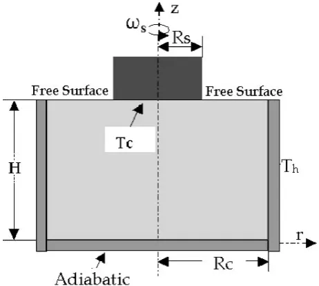
Although the great development in the computer and numerical technologies as well as theories related to crystal growth, it is still impossible to predict precisely the real experimental process with the detail including the appear-ance of inclusion, crack, facet etc. Exact experimental conditions cannot be duplicated completely in a numerical study. A complex model with many trivial details may lead to the difficulty in its result analysis. Therefore, a simplified CZ model typically for the study of unsteady three-dimensional (3D) convection in CZ as shown in Fig. 1 is adopted here. Using the scalesRc,=Rc,2=Rc2 for length, velocity, and
pressure, where and stand for thermal diffusivity and density, the governing equations within the Boussinesq approximation read:
r u ¼0;
@u=@tþ ðu rÞuPrr2u¼ rPþRaPrTnz @T=@tþ ðu rÞT r2T ¼0:
The applied boundary conditions are
z ¼0 :@T=@z¼u ¼v¼w ¼0
r ¼Rc:T ¼Th;u ¼v¼w ¼0
z ¼H
and
05r5Rs:T¼Tc;v ¼w¼0;u¼!sr
z¼H
and
Rs<r5Rc:@T=@z¼w ¼0;@u=@z
¼ Ma½ð1=rÞ@T=@;@v=@z ¼ Ma@T=@r
The dimensionless temperature isT ¼ ðTTcÞ=Twith T ¼ThTc. Other dimensionless parameters include the
Prandtl number Pr¼v=, Rayleigh number Ra¼ TgRc3=v, and Marangoni number Ma¼kTRc=
ðvÞ, wherestands for linear expansion coefficient,vfor kinematic viscosity and gfor the gravitational acceleration. The finite volume method with staggered grids is adopted. The discretization of unbalanced surface tension is same as in Refs. 16–18).
3. Results
Validation of our code and grid resolution for both 2D and 3D cases have been examined, and a 100100 grid is adopted for the 2D cases and a685050grid is used for the unsteady 3D cases.19)The physical properties of LiCAF melt are taken from Refs. 20, 21); the Prandtl number Pr is
1.4, which is smaller than Pr for oxide (Pro(10)) and larger than Pr for semiconductor materials (Pro(0.01)). The geometrical and temperature parameters are measured or evaluated from the experimental conditions for 2-inch (5.08 cm) LiCAF crystal growth, which are referred to as CONDITION 1 in Table 1. The effects of geometrical parameters and temperature difference T on optimal growth are investigated under the conditions listed in Table 1. The crystal diameter can be well controlled automatically with the automatic servo-control systems as adopted in Refs. 1–3) Both pulling rate and crystal rotating rate are prescribed and, in general, are fixed in the all growth process of real crystal growth experiment. As in Refs. 1–3) crystal diameter is controlled automatically by adjusting temperature due to the action of weight sensor in automatic servo-control system. To achieve a striation-free fluorite crystal with high yield, the criteria for the optimal crystal rotation are proposed as below:
(I) a large growth rate,
(II) a flat or relatively flat non-concave melt-crystal interface,
(III) steady convection.
Because the unsteady convection is always undesirable, it should be avoided. In the investigation of criteria (I) and (II), convection is initially assumed to be axisymmetric and steady, and a 2D calculation is performed to save CPU time. Criterion (III) is investigated by unsteady 3D simulations, which are much more time-consuming Criterion (II) is suitable for the present fluoride crystal; however it should be modified for the semiconductors. Based on the previous experimental and theoretical studies, keeping flat interface of crystal-melt is crucial in governing crystal quality. Non-flat interface could be the principal reason for the generation of dislocations and consequently for many undesirable effects such as inhomogeneous distribution of impurities, strains, cracks, low-angle grain boundaries, gas bubble entrapment, facetetc.4–14,22–24)At the melt-crystal interface, latent heatQ
L
is released during solidification and appears as a source term in the energy balance at the solidification interface as
KmjrTmj þQL¼KsjrTsj
A largerQLindicates that more latent is released, and thus
implies a larger growth rate for a fixed crystal size, which is controlled automatically in the automatic servo-control system. A smaller temperature gradient on the melts side
[image:2.595.53.284.72.279.2]Fig. 1 Model of Czochralski crystal growth.
Table 1 Conditions used in this numerical study.
CONDITION 1 2 3 4 5 6 7 8 9 10
T(k) 50 50 50 50 50 50 60 70 50 50
Rc(mm) 50 50 50 50 50 50 50 50 30 75
Rs=Rc 0.5 0.4 0.6 0.5 0.5 0.5 0.5 0.5 0.5 0.5
H=Rc 1 1 1 0.3 0.5 0.8 1 1 1 1
1(rpm) 40 45 35 45 35 35 45 45 60 30
2(rpm) 20 30 15 5 10 20 20 20 30 10
3(rpm) 14 50 10 73 35 16 14 15 >60 7
optimal!s 14 30 10 5 10 16 14 15 30 7
[image:2.595.48.552.643.756.2]results in a largerQLand therefore a larger growth rate if the
temperature gradient on the crystal side remains unchanged. Experimentally, pulling rate for a prescribed crystal size can be adjusted in some degree, however there is a limit for the growth rate, and which is decided by QL¼ KsjrTsj
KmjrTmj. Without losing generality, we assume the crystal
size (required by experiment) and KsjrTsj (under a stable
thermal supply system) as constants roughly. It is obvious that the maximum pulling rate is mainly decided by
KmjrTmj. An equilibrium can be arrived for pulling rate=0
under the condition as KmjrTmj ¼KsjrTsj or QL ¼0, and
also the possible maximum pulling rate is decided by
KmjrTmj, which is controllable by convection in melt. Here,
we define the dimensionless average heat flux q (from the melt to melt-crystal interface) to investigate the effect of crystal rotation on the growth rate:
q¼
Z2
0
ZRs
0 @T
@zr drd
Rs2
:
Marangoni convection is reported by Jing et al.25) to be
responsible for the formation of the 3D spoke pattern on the free surface in 3D numerical simulations, and Hintzet al.26)
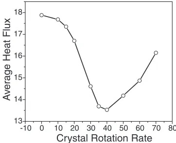
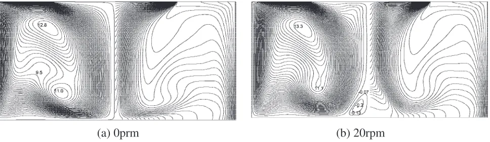
presented that Marangoni convection causes a different 2D flow pattern from the comparison of experiments with water and silicon oil. However, Marangoni convection has typically been ignored in most of the previous model simulations. In the present study, however, the role of Marangoni convection is investigated. As shown in Fig. 2, Marangoni convection results in a shift in the vortex center. The convection structure is similar to the experimental and numerical results of Ref. 26) (compare Fig. 2 with Figs. 2–4 in Ref. 26)). For crystal growth, the most important region nears the interface of the crystal-melt, and Marangoni convection plays an important role here. Under CONDITION 1, a 24%–25% relative error for q is found when Marangoni convection is ignored. This indicates the importance to include Marangoni convection in the CZ model.27)Figure 3 shows a rotating rate around 40 rpm is the choice if only criterion (I), a large growth rate, is considered under the assumption of steady 2D convection.
Wu et al.24) proposed a relative temperature function to evaluate the interface shape, however it does not support readers the image of interface directly. Although the
melt-crystal interface is not simulated directly in our model, we propose a method to evaluate the interface shape from the temperature distribution near melting temperature. The melt-crystal interface is an iso-temperature surface (ITS) ofT ¼
Tm(melting temperature, the solution effect on the melting temperature is ignored here), and the change in shape of the ITS in the neighborhood of the interface forT ¼Tmshould
be continuous. Therefore, the shape of the ITST ¼Tmþ
0:0005is adopted to ascertain the interface withT¼Tm.
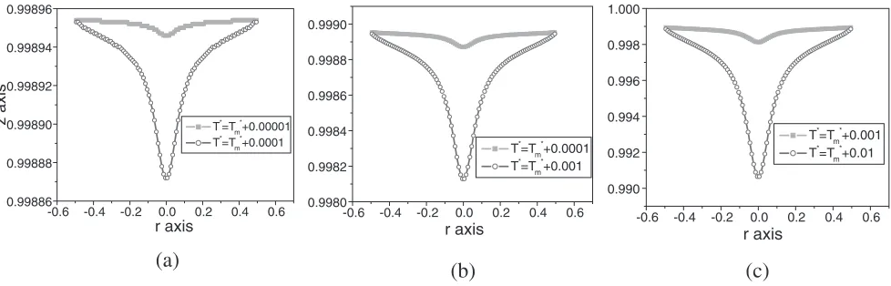
By observing the shape of the ITS forT ¼Tmþ0:00001,
T¼Tmþ0:0001, T¼Tmþ0:001 and T ¼Tmþ
0:01in Fig. 4, we can confirm that ITS varies continuously, and therefore we can estimate the shape of melt-crystal interface qualitatively with ITS T ¼Tmþ0:0005. The
deviation caused by the model of flat crystal interface in the simulation disappears if a real flat melt-crystal interface is realized, and therefore the model will be valid to search for the optimal crystal-rotating rate with the criterion of a flat melt-crystal interface. In the present model, thermal con-duction in the crystal is ignored in the investigation of interface shape, because convection is much stronger than diffusion and conduction in mass and heat transfer, and therefore convection dominates the final interface shape. With the same simulation parameters as in Ref. 28), the ITS
T¼Tmþ0:0005in Fig. 5 is comparable with Figs. 7–9 of Ref. 28), which indicates that the present model excluding thermal conduction in the crystal and also the detail on
(a)
(b)
Fig. 2 Contour plot of temperature (right side) and stream line (left side) for (a) buoyancy convection only and (b) both buoyancy and Marangoni convection under CONDITION 1 without crystal rotation.
-10 0 10 20 30 40 50 60 70 80 13
14 15 16 17 18
A
v
er
age Heat Flux
Crystal Rotation Rate
[image:3.595.62.538.72.206.2] [image:3.595.335.516.263.410.2]crystal growth rate etc. (crystal growth rate is typical very small, e.g.0.8 mm/h for the experiment in our investigated cases) can still be used to evaluate reasonably the interface shape.
As shown in Fig. 6, the shape of the ITS becomes fatter with increasing crystal rotation rate !s between 0–20 rpm,
and the convex cone near the axis becomes sharper and deeper. When!sis increased to 30 rpm, the convex cone near
the axis becomes larger and shape of the surface away from
the center combines both concave and convex structures as in Fig. 7(c). With further increment of !s to 35 rpm, a wavy
interface comprised of 3 concave and 4 convex surfaces as in Fig. 7(d) is observed, and a single concave interface appears with further increase in!sas in Fig. 7(e). Neither an ideal flat
interface nor a trend towards an ideal flat interface is observed in the present study. The optimal value of !s is
about 20 rpm when criteria (I) and (II) for optimal growth under CONDITION 1 are considered.
-0.6 -0.4 -0.2 0.0 0.2 0.4 0.6
0.99886 0.99888 0.99890 0.99892 0.99894 0.99896
z axis
r axis T*
=Tm *
+0.00001 T*
=Tm *
+0.0001
-0.6 -0.4 -0.2 0.0 0.2 0.4 0.6
0.9980 0.9982 0.9984 0.9986 0.9988 0.9990
T*
=Tm *
+0.0001 T*
=Tm*
+0.001
r axis -0.6 -0.4 -0.2 0.0 0.2 0.4 0.6
0.990 0.992 0.994 0.996 0.998 1.000
T*=Tm *
+0.001 T*
=Tm*
+0.01
r axis
(a)
(b)
(c)
Fig. 4 Shape of the iso-temperature line forT¼TmþaandT¼Tmþ10afor (a)a¼0:00001, (b)a¼0:0001and (c)a¼0:001. It
indicates the continuously change of iso-temperature line near crystal-melt interface.
z Axis
-0.6 -0.4 -0.2 0.0 0.2 0.4 0.6 0.670
0.672 0.674 0.676 0.678 0.680
0 rpm
r Axis
z Axis
-0.6 -0.4 -0.2 0.0 0.2 0.4 0.6 0.670
0.672 0.674 0.676 0.678 0.680
5 rpm
r Axis
z Axis
-0.6 -0.4 -0.2 0.0 0.2 0.4 0.6 0.670
0.672 0.674 0.676 0.678 0.680
6 rpm
r Axis
z Axis
-0.6 -0.4 -0.2 0.0 0.2 0.4 0.6 0.670
0.672 0.674 0.676 0.678 0.680
11 rpm
r Axis
Fig. 5 Shape of the iso-temperature lineT¼Tmþ0:0005used to evaluate the shape of the interface under the conditions of Ref. 15).
-0.6 -0.4 -0.2 0.0 0.2 0.4 0.6
0.990 0.991 0.992 0.993 0.994 0.995 0.996 0.997 0.998 0.999 1.000
z axis
r axis
s0 s10 s20 s30 s35
[image:4.595.56.545.73.230.2] [image:4.595.75.523.290.472.2] [image:4.595.87.509.526.633.2]Buoyancy causes the melt to flow upwards near the warm crucible wall and downwards beneath the crystal. The unbalanced surface tension drives hot melt from the warm crucible to the cold crystal at the free surface, and therefore convection is enhanced as shown in Fig. 2. The rotating crystal draws the melt underneath the crystal and throws it outward in the radial direction. This force convection weakens buoyancy and Marangoni convection. With increas-ing !s, this suctioning force increases and the downstream
flow near the axis is gradually weakened. Finally, an upstream flow is formed near the axis at the bottom of the crucible as shown in Fig. 8(b).
The effects of the geometrical parameters and temperature differenceTfor criteria (I) and (II) are investigated, and the results are listed in Table 1. There are several typical interface shapes suggested from the T¼Tmþ0:0005
[image:5.595.49.289.74.169.2]surface in the present study and the sketches are shown in
Fig. 7. Under the assumption of steady 2D convection, no ideal flat interfaces are realized by crystal rotation in our study, and a wavy interface, a mixed convex-concave interface shape, appears before a completely concave one. This is consistent with the report of Ref. 28) for large crystal growth, where a much more complex model is adopted to study the crystal-melt interface.
The experimental result as shown in Fig. 4 of Ref. 5) demonstrates the tendency for interface transition from the initial convex, to wavy interface, and finial concave interface with the reduction of the melt height under same temperature boundary condition and fixed crystal rotating rate. The present numerical simulation supports the experimental result in Ref. 5). The present result also indicates that to keep same interface shape, the crystal rotation rate should be decreased gradually with the decrement of the melt height, however a steep change of crystal rotation rate is believed to be harmful for the crystal quality. The automatic servo-control system for crystal growth as in Refs. 1–3) could perhaps relieve the problem partially, because it can adjust temperature automatically to control diameter, and also the crystal growth is stopped at almost 60% solidification fraction as in Ref. 3).
Retention of steady convection is crucial to avoid striation in a grown crystal. Therefore a series of unsteady 3D numerical simulations are conducted. The results indicate that the convection is steady and axisymmetric without crystal rotation, and it remains steady axisymmetric flow with crystal rotation up to a critical value, then it loses instability to become unsteady 3D convection with increasing further the crystal rotation. Figure 9 shows the iso-surface of
(a) (b) (c)
(d) (e) (f)
Fig. 7 Sketch of interface shapes speculated from iso-temperature line
T¼Tmþ0:0005with different crystal rotation rate under
CONDI-TION 1, except (f) which is under CONDICONDI-TION 4.
(a)
(b)
(c)
(d)
Fig. 9 Iso-surface of temperatureT¼0:8for one period of oscillatory with!s¼20under CONDITION 1.
(a) 0prm
(b) 20rpm
[image:5.595.55.539.468.609.2] [image:5.595.85.512.670.769.2]temperature (T¼0:8), which exhibits unsteady 3D con-vection features for!¼20rpm, and the convective feature is consistent with the report in Ref. 29). The critical crystal rotation rate !critical is 14 rpm< !critical<15 rpm for the
instability, and therefore the optimal rotating rate 3 for criterion (III) is about 14 rpm. The resulting critical crystal rotation under other investigated conditions for the convec-tive instability is listed in the Table 1. The detailed discussion of unsteady 3D convection is presented in Ref. 19).
In the present numerical study, Marangoni convection is found to stabilize convection. Instead of a critical crystal rotation rate of 14 rpm<!critical<15 rpm for convection
instability with the model including Marangoni convection, the resulting3for criterion (III) is less than 10 rpm when Marangoni convection is ignored.
By considering criteria (I), (II) and (III) for optimal growth, the optimal crystal rotation rate is about 14 rpm. For real crystal growth, !s¼10rpm was adopted in the
successful experiment for the growth of 2-inch (5.08 cm) high-quality LiCAF single crystal.2)
Based on the parameter study as shown in Table 1, the results indicate that although three criteria are adopted to determine the optimal crystal rotating rate, criteria (II) and (III) are much more crucial than criteria (I). In the case of CONDITION 1, which approximates 2 inches (5.08 cm) LiCAF crystal growth experiment, the optimal crystal rotation rate is decided finally by the criterion (III), critical crystal rotating rate for the convective instability. However, criterion (II) becomes more important with decreasing crystal size (refer to CONDITION 1, 2 and 9 in Table 1). With the reduction of the melt height, the critical crystal rotating rate
3for the convective instability increases,e.g.3in Table 1 increases from 14 rpm for H=Rc¼1to 16 rpm for H=Rc¼ 0:8, to 35 rpm forH=Rc¼0:5, and to 73 rpm forH=Rc¼0:3
(the resolution for 3 is 1 rpm). On the contrary, 2 in Table 1 decreases with the reduction of the melt height, this conclusion is consistent with the experimental result as shown in Fig. 4 of Ref. 5), where Fig. 4 demonstrated that the interface of crystal-melt changed from initial convex to wavy interface and finial concave interface with the reduction of the melt height. The empirical formula as in Refs. 6, 22, 23) for interface inversion also demonstrated that2decreases with the melt height H. The different tendency for2and3
determines that2becomes more important with decreasing melt height. In the investigated parameter range, the variation of the temperature difference does not result in an obvious change of the optimal crystal rotating rate (refer to CONDITION 1, 7 and 8 in Table 1).
The present numerical study is based on an ideal model, but real experiment is more complex. For LiCAF crystal growth experiment, crystal rotation of 15 rpm and 10 rpm had been applied successfully to 1 inch (2.54 cm) and 2 inches (5.08 cm) crystal growth, respectively,1,2) but when crystal
rotation of 8 rpm is applied to 3 inches crystal growth as in Ref. 3), inclusion appears in the lower part of grown crystal. By increasing crystal rotation rate to 12 rpm for 3-inch case in experiment, crack formed in the grown crystal, and it was solved by change temperature conditions.3) The possible reason for the formation of inclusion in Ref. 3) was speculated to be the interface instability during the crystal
growth, and if the speculation is correct, based on the present study, reducing gradually the crystal rotation rate smoothly is a possible solution of the inclusion, and a concave interface to melt as in Fig. 1 of Ref. 3) is observed, which is speculated to be caused by a concave melt-crystal interface toward to melt. Unfortunately, this proposal cannot be checked right now because the crystal-rotating rate cannot be adjusted automatically by the growth machine in Refs. 2–3 and it is impossible to guarantee crystal rotation slowly and smoothly with a manual way due to its very long growth time (in days and weeks), and it is believed to be harmful for the crystal quality by changing crystal rotation steeply.
In the further study, a global model including radiation in the whole growth system and analysis of thermal stress in crystal should be combined, the theory and model to predict inclusion and crack should also be developed, however it is a long road to the finial success for predicting optimal growth conditions precisely, which is applicable directly into large high-quality crystal growth, by numerical simulation, be-cause the challenge is not only the development of related theory and model, but also the much higher requirement in computational capability of computer and faster algorithm for large crystal growth, where convection probably accesses the turbulence regime with increasing crystal size. Although the convective instability is controllable by adjusting crystal rotation in the present study, it is maybe unavoidable with increasing crystal diameter. Applying the magnetic field can control convection effectively for semiconductor and metal crystal growth, but it is not suitable for fluoride crystal growth, therefore a new technology for convection control should be developed for the further larger high-quality fluoride crystal growth in the future.
4. Conclusion
The optimal crystal rotation for LiCAF crystal growth by the CZ technique is investigated by numerical techniques. The model study indicates that a relatively but never ideally flat interface for 2-inch LiCAF crystal is realized by crystal rotation, and this conclusion is consistent with Ref. 28) for large-size crystal growth. The parameter study is conducted by varying only one parameter in each simulation as shown in Table 1, the result demonstrates that 2 for criterion (II) decreases with the increment of the crucible sizeRc, ratio of
Rs=Rc, and decrement of the melt height; the critical crystal
rotating rate3for the convective instability increases with decreasing melt height and crystal size. For a larger size crystal growth by CZ technique, in addition to controlling a flat or relative flatter interface of crystal-melt, retaining a steady convection is also crucial to determine the optimal crystal-rotating rate.
Acknowledgements
supported by the National Natural Science Foundation of China (Grant No. 10302032).
REFERENCES
1) K. Shimamura, S. L. Baldochi, I. M. Ranieri, H. Sato, T. Fujita, V. Mazzocchi, C. B. R. Parete, C. V. Santilli, N. Sarukura and T. Fukuda: Journal of Crystal Growth223(2001) 383.
2) K. Shimamura, S. L. Baldochi, N. Mujilatu, K. Nakano, Z. Liu, N. Sarukura and T. Fukuda: Journal of Crystal Growth211(2000) 302. 3) K. Shimamura, H. Sato, A. Bensalah, H. Machida, N. Sarukura and T.
Fukuda: Journal of Alloys and Compounds343(2002) 204. 4) P. W. Mokruchnikov: Crystal Reseach and Technology 34 (1999)
1169.
5) M. T. Santos, J. C. Rojo, A. Cintas, L. Arizmendi and E. Dieguez: Journal of Crystal Growth156(1995) 413.
6) S. H. Lee, Y. L. Kim, S. H. Cho and E. P. Yoon: Journal of Crystal Growth125(1992) 175.
7) J. R. Carruthers: Journal of Crystal Growth36(1976) 212.
8) V. Nikolov, K. Iliev and P. Peshev: Journal of Crystal Growth 89
(1983) 324.
9) J. P. Fontaine, G. P. Extremet, V. Chevrier and J. C. Launay: Journal of Crystal Growth139(1994) 67.
10) N. Kobayashi: Journal of Crystal Growth52(1981) 425.
11) J. Trauth and B. C. Grabmaier: Journal of Crystal Growth112(1991) 451.
12) H. Kopetsch: Journal of Crystal Growth102(1990) 505.
13) A. Hirata, M. Tachibana, Y. Okano and T. Fukuda: Journal of Crystal Growth128(1993) 195.
14) T. A. Kinney, D. E. Bornside, R. A. Brown and K. M. Kim: Journal of Crystal Growth126(1993) 413.
15) S. M. Pimputkar and S. Ostrach: Journal of Crystal Growth55(1981) 614.
16) Z. Zeng, H. Mizuseki, K. Shimamura, T. Fukuda, Y. Kawazoe and K. Higashino: Journal of Crystal Growth234(2002) 272.
17) Z. Zeng, H. Mizuseki, K. Higashino, K. Shimamura, T. Fukuda and Y. Kawazoe: Mater. Trans.42(2001) 2322.
18) Z. Zeng, H. Mizuseki, K. Shimamura, T. Fukuda, K. Higashino and Y. Kawazoe: International Journal of Heat and Mass Transfer44(2001) 3765.
19) Z. Zeng, J. Q. Chen, H. Mizuseki, K. Shimamura, T. Fukuda and Y. Kawazoe: Journal Crystal Growth,252(2003) 538.
20) S. Brandon: Modelling and Simulation in Materials Science and Engineering5(1997) 259.
21) V. J. Fratello and C. D. Brandle: Journal of Crystal Growth109(1991) 329.
22) V. Nikolvo, K. Iliev and P. Peshev: Journal of Crystal Growth 89
(1988) 313.
23) V. Nikolvo, K. Iliev and P. Peshev: Journal of Crystal Growth 89
(1988) 324.
24) X. B. Wu, X. Geng and Z. Y. Guo: Journal of Crystal Growth169
(1996) 786–794.
25) C. J. Jing, N. Imaishi, T. Sato and Y. Miyazawa: Journal of Crystal Growth216(2000) 372.
26) P. Hintz and D. Schwabe: Journal of Crystal Growth222(2001) 343. 27) Z. Zeng, J. Q. Chen, H. Mizuseki, T. Shishido, K. Ichinoseki and Y.
Kawazoe: Journal of Thermal Science11(2002) 348. 28) H. Kopetsch: Journal of Crystal Growth102(1990) 505.