Hi NicalonTM Fiber Reinforced CVI SiC Matrix Composites: I Effects of PyC and PyC SiC Multilayers on the Fracture Behaviors and Flexural Properties
6
0
0
Full text
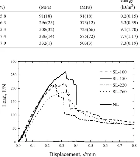
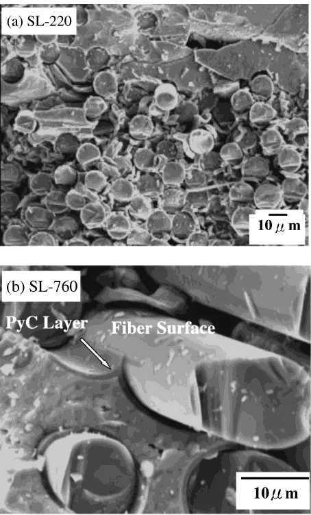
(2) Hi-NicalonTM Fiber-Reinforced CVI-SiC Matrix Composites:. 2569. Table 1 The Hi-NicalonTM /SiC composites with single PyC interlayer.. NL SL-100 SL-150 SL-220 SL-760. Interlayer structure and thickness (nm). Mass density (Mg/m3 ). Porosity. PLS. UFS. (%). (MPa). (MPa). Fracture energy (kJ/m2 ). F/M F/C100(14) /M F/C150(21) /M F/C220(31) /M F/C760(116) /M. 2.51(0.03) 2.48(0.02) 2.52(0.02) 2.44(0.03) 2.41(0.03). 15.8 16.3 15.3 17.4 17.9. 91(18) 296(25) 508(32) 386(14) 332(1). 91(18) 573(12) 723(66) 575(72) 503(3). 0.2(0.15) 5.3(0.39) 9.1(1.70) 7.7(1.17) 7.3(0.19). 2.2 Three point bending test Three bending bars were prepared from each composite. The bars were cut parallel to one of the fiber bundle directions of the fabric cloth using a diamond wheel and both the tensile and compression surfaces were ground using diamond slurry. The final dimension of the bars was L30 × W 4.0× ∼ T 1.5 mm3 . Certain bars were side-surface polished for SEM (scanning electron microscope) examination after the tests. Three-point bending tests (with a support span of 18 mm) were conducted at room temperature. The crosshead speed was 0.0083 mm/s.. 300. 200. 150. 3. Results and Discussion 3.1 Composites with single PyC interlayer Four different composites with single PyC layers of thickness from 100 nm to 760 nm were fabricated, as listed in Table 1, as well as a composite without interlayer. In the column for interlayer structure and thickness in the table, the capital letters, F, M, and C, stand for the fiber, the matrix and the PyC layer, respectively. Included in the parenthesis are the standard deviations in the table. The mass density was obtained from each bending specimen’s mass and volume. The porosity was calculated by: υp = 1 − υf − υPyC − (ρC − υf ρf − υPyC ρPyC )/ρSiC where: υi and ρi are respectively the volume fractions and densities of fibers, PyC, composite, and CVD-SiC. υPyC was estimated from the carbon interlayer thickness. The densities of PyC and CVD-SiC were 2.23 and 3.21 Mg/m3 in this calculation. Typical load-displacement curves of the composites are shown in Fig. 1. Composite NL, in which no intentional interlayer was deposited, exhibited a quite low load maximum. NL. 100. 50. 0 0.0. 2.3 Microstructure characterization All the composites and the morphologies, thicknesses, and uniformities of the interlayers were examined using the JEOL JIM-6700F. The interlayer thickness was measured on the SEM images from 6 areas at the cross-section of each composite with an estimated resolution of ∼ 10 nm. The fracture surfaces, interfacial debonding behavior and fiber pullout lengths were also observed with SEM. Sidepolished specimens were used to observe the propagation/deflection of transversal cracks at fiber/matrix interface. Specimens that did not completely separate during the bending tests were carefully broken apart by hand so that the fracture surfaces could be examined.. SL-100 SL-150 SL-220 SL-760. 250. Load, F/N. Specimen I.D.. 0.1. 0.2. 0.3. 0.4. 0.5. 0.6. 0.7. 0.8. Displacement, d/mm Fig. 1 Representative load-displacement curves of the composites without and with single PyC layers.. and displayed brittle failure, with no signs of toughening. The employment of PyC layers significantly improved the flexural behaviors. All the load-displacement curves of the PyC layered composites displayed several common features: 1) an initial linear region, reflecting the elastic response of the composites, followed by 2) a nonlinear domain of deformation until the load maximum, due mainly to the matrix cracking, interfacial debonding and fiber sliding, and individual fiber failures, 3) quick drop(s) of the load after reached its maximum, perhaps because of the failure of a significant fraction of the fibers, and then a gradual decrease of the load. Different load maximums are shown in Fig. 1 for the various composites. SEM fracture surface examination revealed a smooth and flat fracture surface of composite NL, with no evidence of fiber/matrix debonding and fiber pullout. Debonding and fiber pullouts were observed on the fracture surfaces of all the PyClayered composites, as shown typically in Fig. 2(a). The fiber pullout length was about several micrometers. High magnification SEM images examination revealed that fiber/matrix debonding and interfacial crack deflection in all the PyC layered composites predominantly occurred at the fiber surface, as shown in Fig. 2(b) for composite SL-760. Longer fiber pullout (> 10 µm) is also exhibited in this image. The flexural properties are summarized in Table 1. All the properties, proportional limit stress (PLS), ultimate flexural strength (UFS), and fracture energy were determined from the load-displacement curves according to ASTM C 134197.14) The PLS was the stress corresponding to a 0.01% offset strain. Fracture energies were obtained from the areas below.
(3) 2570. W. Yang et al.. Fig. 3 PyC layer thickness dependence of the PLS and UFS for composites with single PyC layers.. Fig. 2 SEM fracture surface images of (a) composite SL-220 showing debonding and short fiber pullouts and (b) composite SL-760 showing interfacial debonding and crack deflection at fiber-PyC layer interface.. the load-displacement curves till the load maximums. Various flexural properties were exhibited by the composites. Since the composites were fabricated using the same CVI process with the same 2D plain-woven Hi-Nicalon fabric as the reinforcement with similar fiber volume fraction, the PyC layer thickness is considered to be the main reason causing the difference of flexural properties, ignoring the effects of densities due to the very small difference of the densities among the composites. Figure 3 relates the PLS and UFS to the PyC layer thickness. The value of PLS and UFS of composite without layer is essentially the same, and is the lowest one among all the composites. Both the PLS and UFS were improved by the use of PyC layers. The strength increased quickly with increasing the layer thickness up to 150 nm, beyond which decreased gradually. When the PyC layer is thicker than ∼ 200 nm, the PLS and UFS showed little decrease with the PyC layer thickness. The highest individual specimen PLS and UFS were 539 MPa and 789 MPa, obtained from composite SL-150, which was deposited with 150 nm-thick PyC interlayer. This composite also yielded the largest fracture energy of 9.1 kJ/m2 , as shown in Table 1. These indicate an optimum PyC layer thickness of ∼ 150 nm to maximize the flexural properties. Similar results have been reported with 1D Nicalon/PyC/SiC minicomposites and. 2D plain-woven Nicalon/SiC composites.5, 9) The best tensile properties (for the 1D minicomposites) and flexural properties (for the 2D composites) were obtained with carbon coating thickness of ∼ 200 nm and ∼ 170 nm, respectively. As clarified by Naslain,9) the main functions of the interface in a continuous fiber reinforced ceramic matrix composite are to transfer the load from the matrix to the fibers to take the advantages of the strong reinforcement fibers and to deflect the matrix cracks at the interface to gain the composites improved fracture tolerance. The load transfer function generally requires strong enough fiber/matrix bonding while weaker bonding is better for deflecting impinge matrix cracks at interface through interfacial debonding. The interfacial strength can be modified through the deposition of a carbon interlayer due to its compliant nature. It was found8) that the interfacial shear strength of plain-woven NicalonCG(commercial grade) fiber-reinforced CVI-SiC matrix composites decreased with increasing the carbon interlayer thickness. Thicker carbon layer absorbs more residual radial clamping stress in the fiber, and hence, results in decreased interfacial shear strength. Therefore, it is likely that the 150 nm PyC layer yielded the present composite SL-150 an interfacial strength that might provide a best balance between load transfer and matrix crack deflections at the interface, and therefore, resulted in the highest flexural strength of the composite among all the composites. For CVI-SiC/SiC composites, the residual radial clamping stress in the fiber is mainly from the thermal residual stress (TRS) resulting from different thermal expansion during process. The radial coefficient of thermal expansion (CTE) of Hi-Nicalon fiber at ambient temperature is 3.5 × 10⁻⁶ K−1 ,13) versus slightly smaller value of 3.2 × 10⁻⁶ K−1 13) for the Nicalon-CG fiber. The CTE of typical CVD(chemical vapor deposition)-SiC is 4.6 × 10⁻⁶ K−1 ,13) much larger than both the two fibers. Therefore, a residual radial clamping stress is exposed to the fibers in both Hi-Nicalon and Nicalon-CG reinforced CVISiC/SiC composites. Smaller TRS is estimated in CVI-HiNicalon/SiC composites than in CVI-Nicalon/SiC composites due to smaller mismatch of CTE between Hi-Nicalon fiber and CVD-SiC. Thus, thinner compliant interlayer is expected in CVI-Hi-Nicalon/SiC composites to absorb the TRS. This might provide an explanation for the difference of above op-.
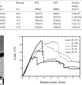
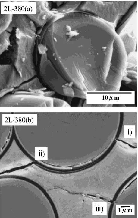
(4) Hi-NicalonTM Fiber-Reinforced CVI-SiC Matrix Composites: Table 2. 2571. The Hi-NicalonTM /SiC composites with PyC-SiC multilayers.. Specimen I.D.. Interlayer structure and thickness (nm). Mass density (Mg/m3 ). Porosity. PLS. UFS. (%). (MPa). (MPa). Fracture energy (kJ/m2 ). 2L-125 2L-380 3L-80 3L-50 4L-50. F/SiC250(41) /C125(18) /M. 2.42(0.02) 2.41(0.02) 2.52(0.02) 2.51(0.03) 2.44(0.04). 18.4 18.4 15.3 15.6 17.8. 342(57) 294(28) 368(14) 353(41) 222(24). 640(5) 563(52) 518(61) 482(62) 344(26). 5.9(0.47) 11.8(2.93) 7.3(1.01) 5.2(1.31) 2.9(2.01). F/SiC250(42) /C380(57) /M F/C80(13) /SiC150(25) /C70(16) /M F/C50(8) /SiC150(23) /C50(11) /M F/SiC50 /C50 /SiC100 /C50 /M. 250. 2L-125 2L-380 3L-80 3L-50 4L-50. Load, F/N. 200. 150. 100. 50. 0 0.0. 0.1. 0.2. 0.3. 0.4. 0.5. 0.6. 0.7. 0.8. Displacement, d/mm Fig. 4. SEM image of composite 2L-380 showing the interlayers.. timum carbon layer thickness for the two composite systems, slightly thinner for Hi-NicalonTM /SiC composites. The debonding and crack deflection predominantly occurred at the very surface of the Hi-NicalonTM fibers. This indicated a weaker bonding at the fiber-PyC interface rather than at the PyC-matrix interface, presumably due to a graphite layer or very thin oxide layer formation on the as-received HiNicalonTM fiber surface.15) 3.2 Composites with PyC-SiC multilayers The interlayer structures and densities as well as porosities of composites with PyC-SiC multilayers are given in Table 2. Five composites were fabricated with various PyC-SiC multilayers. Figure 4 shows SEM image of the interlayers of composite 2L-380. A SiC layer of 250 nm in thickness was deposited on the fibers before the deposition of a 380 nm-thick PyC layer. SEM interlayer examination of the other multilayered composites also confirmed a successful deposition of the PyC-SiC multilayers with rather good through-thickness uniformity, as indicated in Table 2. The load-displacement curves of the multilayered composites are shown in Fig. 5, which exhibits similar features as those for single PyC layered ones. Figure 6 shows the SEM images of a pulled out fiber (Fig. 6(a)) and transverse crack deflections and propagations at interfaces (Fig. 6(b)) of composite 2L-380. Both images were taken from areas near to the tensile surface of the specimen. Figure 6(b) was taken from the side-surface of the specimen that was pre-polished before the bending test. Figure 6(a) revealed that the surface of the pulled out fiber was partially. Fig. 5 Representative load-displacement curves of the composites with PyC-SiC multilayers.. covered with interlayer flakes, which indicates that the matrix cracks were double deflected by the multilayers and the fiber surface. Several interfacial cracking behaviors are demonstrated on Fig. 6(b): i) crack was arrested by the PyC layer. ii) crack was deflected by SiC sub-layer. iii) crack was deflected at the fiber surface. Similar interfacial cracking behavior was also observed from the fracture surface of another bi-layered composite, 2L-125. Crack deflection and propagation within the multilayers was also observed on the fracture surfaces of composite 3L-80 and 3L-50, but not found on the fracture surface of composite 4L-50. Matrix cracks in composite 4L-50 mostly went directly through the multilayers and were deflected at the fiber-interlayer interface, as that of single PyC layered composites. The PLS, UFS and the fracture energy of composites with multilayers were also extracted from the load-displacement curves and are listed in Table 2. Although various flexural properties were demonstrated by the multilayered composites, no obvious effect of multilayers on the flexural strength could be noticed compared with that of single PyC layered composites. Similar results have been drawn by Bertrand, et al.,12) and Besmann, et al.,16) However, as shown before, much complex interfacial cracking and debonding behaviors were demonstrated on the fracture surface of the multilayered composites. The interfacial debonding and cracking behaviors of composites 2L-125 and 2L-380 indicate that the deposition of a 250 nm-thick isothermal CVI-SiC layer on asreceived Hi-Nicalon fibers prior to PyC layer could control the fiber/matrix debonding and fiber sliding within the SiCPyC layers rather than at the very fiber surface. This would.
(5) 2572. W. Yang et al.. Fig. 7 First PyC layer thickness dependence of the PLS and UFS of the Hi-Nicalon/SiC composites.. Fig. 6 SEM images of composite 2L-380 displaying the debonding and interfacial crack deflection and propagation behaviors (Fig. 6(b): i) crack was arrested by the PyC layer. ii) crack was deflected by SiC sub-layer. iii) crack was deflected at the fiber surface).. be helpful for preventing the fibers from degradation when applied under severe conditions such as high temperature oxidation environment. In addition, although the multilayered composites did not show clear trend of larger fracture energies than those of single PyC layered ones except composite 2L-380 that yielded the largest fracture energy, 11.8 kJ/m2 , among all the composites, a contribution to toughness can be expected from the multilayers due to the complex interfacial cracking behaviors. The SEM fracture surface examinations revealed that although different interfacial debonding and cracking behaviors were exhibited by the multilayered composites, the first PyC layer to the fiber demonstrated the most frequent debonding. When SiC layer was first coated on the fiber (2L-125, 2L-380, and 4L-50), debonding occurred at the SiC-PyC layers interface except composite 4L-50, in which the SiC layer thickness was very thin. When the first layer was PyC (composites 3L-80, 3L-50), debonding occurred mostly at the fiber/PyC layer interface although simultaneous debonding and crack deflections at the SiC-PyC layers interface were also often observed. These observations suggest that the first carbon layer near to the fiber is a relatively weak link in the multilayered composites, and thus, has significant affection on the interfacial properties. Rebillat et al.10) has also reported that the. interfacial characteristics seemed to be related to the thickness of the first carbon layer on the fibers in as-received Nicalon fiber reinforced CVI SiC/SiC composites with (C-SiC)n interlayers. Therefore, the PLS and UFS of the multilayered composites were related to the first PyC layer thickness and the results are given in Fig. 7. Figure 7 shows that considering the standard deviations of both PyC layer thickness and flexural strengths, the PLS and UFS of the multilayered composites fit quite well into the trends for those of composites with single PyC layers, which indicates that the mechanical properties of the composites are largely affected by the first PyC layer. This is in agreement with the fracture surface observation that the first PyC layer demonstrated the most frequent debonding. Although the first PyC layer demonstrated the most frequent debonding, the flexural properties and interfacial cracking behaviors studies showed that the stiff SiC sub-layer in the multilayered composites could provide more chance for the deflection or branching a matrix crack without the loss of the flexural strength of the composites. Therefore, it is possible to design SiC/SiC composites with multilayers in which compliant sub-layer(s) such as PyC is used for modifying the interfacial strength while stiff sub-layer(s) such as SiC is used for controlling the interfacial cracking behaviors. This stiff layer(s) can also, to some extent, protect the reinforcement fibers (especially when it is first deposited on the fibers) and the compliant layer(s) from environmental attacks when the material is appropriately selected. Care should be taken on the amount or thickness of the first compliant layer for desired interfacial bonding and therefore, desired mechanical properties of the composites. 4. Conclusions 2D plain-woven CVI-Hi-NicalonTM /SiC composites with single PyC interlayers of different thickness and with various PyC-SiC multilayers have been developed. The flexural properties and the effects of the various interlayers were investigated. The conclusions are: (1) PLS and UFS of the composites displayed close dependence on the first PyC layers. Both the PLS and UFS showed sharp increase with the increase of the PyC layer.
(6) Hi-NicalonTM Fiber-Reinforced CVI-SiC Matrix Composites:. thickness till ∼ 150 nm, and then decreased gradually. When the PyC layer was thicker than ∼ 200 nm, the PLS and UFS showed little change via the PyC layer thickness. The optimum PyC layer thickness has been defined to be ∼ 150 nm, in terms of flexural properties. (2) Fiber pullouts were observed for all the interlayered composites. Debonding and crack deflection predominantly occurred at the fiber-PyC layer interface for single PyC layered composites. Various interfacial debondings and crack deflections were observed for composites with PyC-SiC multilayers. (3) The flexural strength was not significantly affected by the multilayers which contain stiff SiC sub-layer(s). The SiC sub-layer showed the ability to control the interfacial cracking within the multilayers rather than at the fiber surface. Therefore, it is possible to design SiC/SiC composites with multilayers in which compliant sub-layer(s) such as PyC is used for modifying the interfacial strength while stiff sub-layer(s) such as SiC is used for controlling the interfacial cracking behaviors, resulting in possible further improved performances (against environment attacks) of the composites when the interphase materials are appropriately selected. Acknowledgements This work was supported by the CREST, Japan Science and Technology Corporation.. 2573. REFERENCES 1) T. Noda, H. Araki, F. Abe and M. Okada: J. Nucl. Mater. 191–194 (1992) 539–43. 2) D. Brewer: Mater. Sci. & Eng. A261 (1999) 284–291. 3) L. L. Snead, R. H. Jones, A. Kohyama and P. Finici: J. Nucl. Mater. 219 (1995) 55–62. 4) T. M. Besmann, D. P. Stinton, E. R. Kupp, S. Shanmugham and P. K. Liaw: J. Mater. Res. Soc. Symp. Proc. 458 (1997) 147–159. 5) R. A. Lowden: Ceram. Trans. 19 (1991) 619–630. 6) R. N. Singh and S. K. Reddy: J. Am. Ceram. Soc. 79 [1] (1996) 137– 147. 7) R. W. Rice, J. R. Spann, D. Lewis and W. Coblenz: Ceram. Eng. Sci. Proc. 2 [7–8] (1981) 683–701. 8) E. Lara-Curzio, M. K. Ferber and R. A. Lowden: Ceram. Eng. Sci. Proc. 15 [5] (1994) 989–1000. 9) R. Naslain: Ceram. Trans. 58 (1996) 23–29. 10) F. Rebillat, J. Lamon, R. Naslain, E. Lara-Curzio, M. K. Ferber and T. M. Besmann: J. Am. Ceram. Soc. 81 [9] (1998) 2315–2326. 11) C. Droillard and J. Lamon: J. Am. Ceram. Soc. 79 [4] (1996) 849–858. 12) S. Bertrand, P. Forio, R. Pailler and J. Lamon: J. Am. Ceram. Soc. 82 [9] (1999) 2465–2473. 13) W. Yang: Development of CVI Process and Property Evaluation of CVISiC/SiC Composites, Doctoral thesis, Institute of Advanced Energy, Kyoto University, 2002. 14) ASTM C 1341–97 (2000) 509–526. 15) Y. Katoh, A. Kohyama, T. Hinoki, W. Yang and W. Zhang: Ceram. Eng. & Sci. Proc. 21 [3] (2000) 399–406. 16) T. M. Besmann, E. R. Kupp, E. Lara-Curzio and K. L. More: J. Am. Ceram. Soc. 83 [12] (2000) 3014–3020..
(7)
Figure
Related documents
The total coliform count from this study range between 25cfu/100ml in Joju and too numerous to count (TNTC) in Oju-Ore, Sango, Okede and Ijamido HH water samples as
In the study presented here, we selected three rep- resentative pathogenic PV mAbs cloned from 3 different PV patients: F706, an anti-Dsg3 IgG4 isolated by heterohybridoma, F779,
19% serve a county. Fourteen per cent of the centers provide service for adjoining states in addition to the states in which they are located; usually these adjoining states have
National Conference on Technical Vocational Education, Training and Skills Development: A Roadmap for Empowerment (Dec. 2008): Ministry of Human Resource Development, Department
In this section we introduce primitive recursive set theory with infinity (PRSω), which will be the default base theory for the rest of this thesis (occasionally exten- ded by
HCC is developing in 85% in cirrhosis hepatis Chronic liver damage Hepatocita regeneration Cirrhosis Genetic changes
This essay asserts that to effectively degrade and ultimately destroy the Islamic State of Iraq and Syria (ISIS), and to topple the Bashar al-Assad’s regime, the international
The encryption operation for PBES2 consists of the following steps, which encrypt a message M under a password P to produce a ciphertext C, applying a
