<2/ 0795,<376 70 574/-=4,9 -47=.; 36 ;839,4
1,4,>3/;
-I?NC 4LQGOC .L@@O
, <FCOGO ;Q@JGPPCB DLN PFC .CENCC LD 8F. ?P PFC
=KGRCNOGPU LD ;P ,KBNCSO
&$$)
0QII JCP?B?P? DLN PFGO GPCJ GO ?R?GI?@IC GK 9COC?NAF+;P,KBNCSO*0QII<CTP
?P*
FPPM*##NCOC?NAF!NCMLOGPLNU"OP!?KBNCSO"?A"QH#
8IC?OC QOC PFGO GBCKPGDGCN PL AGPC LN IGKH PL PFGO GPCJ*
FPPM*##FBI"F?KBIC"KCP#%$$&'#&%(
<FGO GPCJ GO MNLPCAPCB @U LNGEGK?I ALMUNGEFP
The Formation of Molecular Clouds in Spiral Galaxies
Clare Louise Dobbs
University of St Andrews
Submitted for the degree of Ph.D.
DECLARATION
I, Clare Louise Dobbs, hereby certify that this thesis, which is approximately 45,000 words in length, has been written by me, that it is the record of work carried out by me and that it has not been submitted in any previous application for a higher degree.
February 15, 2007
I was admitted as a research student in October 2003 and as a candidate for the degree of PhD in October 2003; the higher study for which this is a record was carried out in the University of St Andrews between 2003 and 2006.
February 15, 2007
In submitting this thesis to the University of St Andrews I understand that I am giving permission for it to be made available for use in accordance with the regulations of the University Library for the time being in force, subject to any copyright vested in the work not being affected thereby. I also understand that the title and abstract will be published, and that a copy of the work may be made and supplied to any bona fide library or research worker, that my thesis will be electronically accessible for personal or research use, and that the library has the right to migrate my thesis into new electronic forms as required to ensure continued access to the thesis. I have obtained any third-party copyright permissions that may be required in order to allow such access and migration.
February 15, 2007
I hereby certify that the candidate has fulfilled the conditions of the Resolution and Reg-ulations appropriate for the degree of Ph.D. in the University of St Andrews and that the candidate is qualified to submit this thesis in application for that degree.
THE UNIVERSITY OF ST. ANDREWS
Clare Louise Dobbs
Submitted for the degree of Ph.D.
February 15, 2007
University of St Andrews
ABSTRACT
THE UNIVERSITY OF ST. ANDREWS
Submitted for the degree of Ph.D.
February 15, 2007
ABSTRACT
ACKNOWLEDGMENTS
My thanks go mostly to my supervisor, Ian Bonnell. His help over the last 3 years, remarkable enthusiasm and constant encouragement have been invaluable. I would also like to thank Jim Pringle, who collaborated on some of this work, and clarified much of the discussion of the dynamics in Chapter 4. I further acknowledge UKAFF (UK Astrophysical Fluids Facility) for granting me large amounts of computer time to run many of these simulations.
CONTENTS
Declaration i
Abstract ii
Acknowledgments iii
1 Introduction 1
1.1 Overview . . . 1
1.2 The Interstellar Medium . . . 2
1.3 Molecular clouds: Observations . . . 4
1.3.1 Tracers of molecular gas and HISA . . . 4
1.3.2 Molecular cloud surveys in the Milky Way . . . 5
1.3.3 CO observations in external galaxies . . . 9
1.4 Molecular clouds: Theories . . . 11
1.4.1 Lifetimes of molecular clouds . . . 14
1.5 Previous numerical work . . . 15
1.6 Outline of Thesis . . . 16
2 Smoothed Particle Hydrodynamics 18 2.1 The SPH equations . . . 18
2.2 SPH and shocks . . . 20
2.2.1 Viscosity switch . . . 20
2.2.2 XSPH . . . 21
2.4 Particle penetration . . . 23
2.4.1 Particle penetration with different Mach number shocks . . . 23
2.4.2 Increasing the source term . . . 26
2.4.3 Particle penetration dependence on the XSPH parameter . . . 27
2.4.4 Varying the initial distribution . . . 27
2.5 Comparison with analytical solutions . . . 28
2.5.1 Isothermal shocks . . . 30
2.5.2 Adiabatic shocks . . . 31
2.6 Summary of SPH, XSPH,αSPH andαXSPH . . . 33
3 The Velocity Dispersion in Molecular Clouds 37 3.1 Turbulence and structure in molecular clouds . . . 37
3.2 Numerical simulations of clumpy, fractal and uniform shocks . . . 39
3.2.1 Shock tube test . . . 40
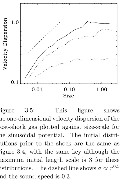
3.2.2 Sinusoidal potential . . . 40
3.2.3 Morphology of the shocks . . . 41
3.2.4 Velocity dispersion . . . 42
3.2.5 Oblique shocks . . . 46
3.2.6 Mass loading . . . 48
3.3 Analytical models . . . 50
3.3.1 Collision of two clumps . . . 50
3.3.2 Multiple collisions of clumps . . . 53
3.4 Summary . . . 55
4 Gas Dynamics in a Spiral Potential 56 4.1 Spiral Galaxies . . . 57
4.2 Spiral Density Waves . . . 58
4.3 Galactic Potential . . . 59
4.3.1 Comparison with the Milky Way . . . 60
4.5 Initial conditions and details of simulations . . . 62
4.6 Overall view of simulations . . . 63
4.6.1 Density and structure of disk . . . 66
4.6.2 Evolution of highest resolution run . . . 67
4.6.3 Location of the spiral shock . . . 67
4.7 The dynamics of spiral shocks . . . 69
4.7.1 Structure formation in the spiral arms . . . 70
4.7.2 Spacing of clumps . . . 77
4.7.3 The velocity dispersion in the spiral arms . . . 77
4.8 Spurs and feathering . . . 78
4.8.1 The formation of spurs . . . 78
4.8.2 Interarm features in spiral galaxies . . . 84
4.8.3 Comparison with other numerical and theoretical work . . . 84
5 The Formation of Molecular Clouds 86 5.1 The formation of H2 . . . 86
5.1.1 Molecular gas density . . . 88
5.1.2 Application to simulations . . . 90
5.2 Dependence of H2 formation on temperature . . . 92
5.3 High resolution simulation . . . 94
5.3.1 Molecular gas and spiral arms . . . 96
5.3.2 Dependence of H2 formation on total disk mass and photodissocia-tion rate . . . 96
5.4 Observational comparison of molecular cloud properties . . . 99
5.5 Summary . . . 101
6 Molecular cloud formation in a multi-phase medium 104 6.1 Details of the multi-phase simulation . . . 104
6.2 Structure of the disk . . . 105
6.2.2 Properties of molecular gas clumps . . . 111
6.2.3 Interarm and spiral arm molecular gas . . . 114
6.3 Summary . . . 117
7 Conclusions and Future Work 118
7.1 Conclusions . . . 118
CHAPTER 1
Introduction
1.1
Overview
The problem of molecular cloud formation has been central to research in star formation and the interstellar medium (ISM) for the last 30 years or so. The benefits of studying molecular cloud formation are fundamental to both. Any theory of star formation depends on the physical properties of molecular clouds. Consequently the outcome from theoretical or numerical results, such as the initial mass function, is related to the initial conditions assumed. The ideal way to investigate star formation, in particular with numerical simu-lations, is thus to explicitly include molecular cloud formation and continue calculations to star forming scales. Then both the properties of molecular clouds, and their influence on star formation, can be monitored as the clouds evolve. Understanding molecular cloud formation will also provide a clearer indication of the nature and physics of the ISM. Is gas in the ISM on the verge of forming molecular clouds spontaneously or are triggering events usually required? This will depend on the dominant physics e.g. gravity, turbu-lence, spiral shocks, feedback, which governs molecular cloud formation. Does a significant fraction of the ISM need to be cold HI or even pre-existing molecular gas for molecular cloud formation to occur? Finally, the process(es) of molecular cloud formation could also explain the spiral structure of galaxies, most clearly identified by the youngest star forming regions. What is the relation between spiral structure and molecular clouds? Does spiral structure decide the location of molecular clouds, or does self regulating star formation produce spiral structure?
Some recent attempts have been made to accommodate the ISM, star formation and spiral structure into a self consistent theory (Elmegreen, 2002; Krumholz & McKee, 2005). Turbulence and self gravity are prevalent in current ideas, following the leading theoretical work of the last 2 or 3 decades by Elmegreen and others, and the results of numerical simulations of interstellar turbulence (Elmegreen & Scalo, 2004). These theories aim to predict the star formation rate from the large scale properties of the galaxy, in particular to find a theoretical explanation for the observed Kennicutt (Kennicutt, 1989) law
SF R∝Σα (1.1)
of Equation 1.1 depends on the molecular cloud properties which determine how much of the ISM will be unstable to star formation.
Observationally, molecular clouds were first detected in the early 1970s (e.g. Solomon et al. 1972; Scoville & Solomon 1973) and surveys since the 1980s have analysed their properties and distribution in the Galaxy. Until recently, there has been little numerical work on molecular cloud formation, largely because of the computational requirements and complex chemistry involved. Numerical studies have predominantly focused on star formation, following the evolution of a molecular cloud (e.g. Bate 1998; Stone et al. 1998; Klessen & Burkert 2001; Bate et al. 2003; Dobbs et al. 2005). Some authors are now tak-ing a step back and modelltak-ing the condensation of molecular clouds (Glover & Mac Low, 2006b) or cold HI regions (Audit & Hennebelle, 2005; Heitsch et al., 2005) in turbulent gas. Accurately simulating molecular cloud formation on galactic scales is still some way off. However this thesis makes one of the first attempts to model this problem. Hydrody-namical simulations of a galactic disk are described, which reveal the formation of dense clouds in the ISM. A criterion based on the chemistry of interstellar shocks is applied to show when they will contain molecular gas.
The rest of the introduction provides a brief summary of the properties and en-vironment of the ISM before concentrating on molecular clouds. The main results from observational surveys and theories regarding molecular clouds are discussed.
1.2
The Interstellar Medium
The interstellar medium consists predominantly of neutral atomic (HI), molecular (H2) and
ionized (HII) hydrogen. In our own Galaxy, approximately 70% of the ISM is hydrogen, 1% dust and the rest mostly helium. Overall the ISM is thought to contain 1/10 of the total mass present in stars and gas. Galaxies can contain varying degrees of molecular gas - with substantial HI and very little H2, or vice versa. For radii between 1.7 kpc and
8.5 kpc in the Galaxy, the mass of HI is 1−1.5×10⁹ M
(Dame, 1993; Wolfire et al.,
2003) and the mass of H2 is 6 ×10⁸ M (Bronfman et al., 2000). Figure 1.1 shows the
variation in the HI and H2 (azimuthally averaged) surface density with radius for the
Galaxy (Wolfire et al., 2003), which is qualitatively typical of spiral galaxies. Though not included in Figure 1.1, nearly all of the gas in the centre of spiral galaxies is molecular. With increasing radius, the H2 surface density decreases exponentially, although Heyer
et al. (1998) find that there is a sharp cut-off beyond the Perseus arm (at galocentric radii
&12 kpc). There is some controversy as to whether undetected H2lies in the outer regions
of galaxies (Allen, 2004), in which case there may be a substantial amount of H2 which is
not currently observed. The density of dust, on which the formation of H2 is dependent
(Chapter 6), is largely proportional to the total gas density.
The components of the ISM span a wide range of temperatures and densities, but the distribution of atomic hydrogen is usually described by a 3 phase medium, following the model of McKee & Ostriker (1977). The different components have temperatures of approximately T = 100 K (the cold neutral medium (CNM)), T = 104 K (the warm
Figure 1.1: The surface column density of HI, H2 and total HI + H2 are shown for the
Galaxy (Wolfire et. al., 2003). For comparison, the surface density of HII at 8.5 kpc is 0.3 M pc−2.
cosmic ray and photoionization heating and collisional cooling with metals such as CII, OI and CI. Presumably gas outside these regimes is undergoing a transition from one phase to another, or is the result of dynamical interaction between different phases. Simulations of the ISM suggest up to 1/3 of the gas is in the unstable regime between the CNM and WNM (Piontek & Ostriker, 2005; Audit & Hennebelle, 2005). Supernovae eject the hot diffuse gas into the ISM, which fills large regions between the colder clouds. The amount of gas present in each component is not easy to determine observationally, however estimates of the filling factors, densities and scale heights are shown in Table 1.1 using the values in Cox (2005) (the WNM was split into 2 different density components). The last column is a simple estimate of the percentage by mass of each component. As the filling factors only add up to 0.46, there appears to be considerable ’empty space’, possibly permeated by an even more diffuse, hotter component of gas (Cox, 2005). The cold HI contains most of the mass but occupies a very small fraction of the volume. At present, this gas is the most likely precursor to molecular clouds, which, located within CNM clouds, have an even smaller filling factor.
In the McKee & Ostriker (1977) model, the hot diffuse gas pervades much of the galactic disk, embedded with cold clouds. However, in addition the ISM contains many remarkable structures such as supershells, cavities and tunnels, of which some may be linked to supernova remnants or OB associations, whilst others remain unexplained. The ISM is now recognised as highly turbulent (Elmegreen & Scalo, 2004) since average velocity dispersions in the gas exceed the thermal sound speeds (Boulares & Cox, 1990). These two observations have lead to an alternative view that the distribution of the ISM is essentially fractal in nature (Elmegreen, 1997).
Molecular clouds are the coldest, most dense regions of the ISM. The typical density of molecular clouds is 100−105 cm−3 and their temperature is usually 10-20 K, although
Component Scale height Density Filling Factor Estimated % of
(pc) (cm−3) ISM by mass
CNM 120 30 0.013 58
WNM (a) 300 1 0.194 29
WNM (b) 400 0.36 0.174 9
HIM 1000 0.3 0.083 3
Table 1.1: Table showing properties in relation to the distribution of the different compo-nents of atomic hydrogen in the ISM. The scale heights, densities and filling factors are taken from Cox (2005).
dense cores embedded in the molecular clouds, usually of order 1 pc or less in size and containing several M or more. The vast majority of star formation takes place in Giant
Molecular Clouds1 (GMCs), of mass > 104 M
(Blitz & Williams, 1999). The range of
observed masses of molecular clouds nevertheless extends from <10 Mto 107 M, with
sizes of <1 pc (Heyer et al., 2001) to 100 pc or more (Dame et al., 1986). As sites of star formation though, GMCs are considered of most relevance. The majority of GMC’s are thought to contain star formation; the cloud G216-2.5 is one of the only GMCs that have been observed locally without star formation (Maddalena & Thaddeus, 1985).
1.3
Molecular clouds: Observations
1.3.1 Tracers of molecular gas and HISA
The H2molecule, of which molecular clouds predominantly consist, is extremely stable, and
cannot be detected directly in a cold molecular cloud. Over 100 more complex molecules have been detected in the ISM, formed on dust grains in a similar way to H2, but with
much lower abundances. These include HCN, SiO, C2, H20 and CS, but most observations
measure CO (J=1-0) emission, since 12CO is easily excited and the most abundant of
molecules after H2. Other molecular tracers are sometimes used to study the denser
regions and internal structure of molecular clouds where 12CO becomes optically thick
e.g. CS observations to trace parsec-scale molecular cloud structure (Greaves & Williams, 1994), or HCN to detect starless cores (Yun et al., 1999). The estimated abundance of the tracer molecule is usually used to determine a conversion factor between the integrated luminosity and the H2 column density.
12CO has been used most extensively for observations of molecular clouds, although
it is now argued that 12CO may not accurately trace H
2. 12CO is in fact so abundant that
the densest cloud cores become saturated in 12CO emission (Lada et al., 2006).
Conse-quently, calculations of the mass of molecular clouds with the assumption of a constant H2 to CO conversion factor may be inaccurate. The most recent surveys e.g. the FCRAO
Galactic Ring Survey (Jackson et al., 2006), have instead used the 13CO isotope, which
is believed to be a better tracer of the H2 column density, but an analysis of molecular
1
There is no actual definition of a GMC, but the convention used in this thesis is that GMCs have a mass
of H2greater than>10 4
clouds from these surveys is not available yet. There are also concerns that CO may not trace H2 in low density regions. Allen & Lequeux (1993) examine dust clouds in M31
away from ongoing star formation. These clouds emit faint CO, but are expected to have masses of 107 M
. They conclude that the molecular gas is too cold to be able to detect
higher levels of CO emission, and further suggest cold molecular gas is abundant in the outer regions of the Galaxy (Lequeux et al., 1993). High latitude molecular clouds are found in the Galaxy without CO emission (eg. Blitz et al. (1990)), but these tend to be lower mass (10 M) diffuse clouds.
The main observational technique with which to compare molecular emission is dust extinction mapping. The extinction can be measured from star counts, by comparing the number of stars in a region of a molecular cloud to those in an unobscured part of the sky, below a certain magnitude threshold (e.g. Bok 1956; Encrenaz et al. 1975; Dickman 1978a; Lada et al. 1994). More recently the extinction has been measured from near IR color excess, the change in color of background stars due to extinction. The column density is assumed proportional to the extinction, so density profiles of molecular cloud cores can be found (Alves et al., 2001, 1998). This process is now starting to be applied to Galactic and extragalactic molecular clouds (Lada et al., 2006). HI can also be used to compare the densities of molecular clouds determined from CO observations. Photodissociation regions (PDRs) lie on the edge of molecular clouds where molecular gas is being converted to atomic gas by photodissociation from young stars. By equating the photodissociation rate with the formation rate of molecular hydrogen, the overall density of atomic and molecular gas can be ascertained (Allen et al., 2004).
The observations of HISA (HI self absorption) clouds of cold atomic hydrogen are likely to be very relevant for future studies of molecular cloud formation. The HISA clouds are denser and colder than usual for atomic hydrogen in the ISM, suggesting they may represent a transition from atomic to molecular gas (Klaassen et al., 2005; Kavars et al., 2005; Gibson et al., 2005). These features are revealed when cold (<100 K) atomic hydrogen is situated in front of a background HI medium (100 −150 K) and dips are observed in the HI emission. The difficulty lies in distinguishing real features from changes in the background emission, as well as requiring the geometry that both the HISA and the background emission lie along the line of sight. The Canadian Galactic Plane Survey (Taylor et al., 2003) has provided mapping of HISA in the Perseus arm (Gibson et al., 2000, 2005) and 70 HISA complexes have been analysed in the Southern Galactic Plane (Kavars et al., 2005). Some, but not all of the HISA clouds are also associated with CO emission and therefore molecular hydrogen, although again a significant fraction of the gas may be molecular without producing CO emission (Klaassen et al., 2005).
1.3.2 Molecular cloud surveys in the Milky Way
The main large-scale CO surveys of the Galaxy include the Massachusetts-Stony Brook CO Galactic Plane Survey (Solomon et al., 1985), Columbia CO survey (Cohen et al., 1986), the FCRAO Outer Galaxy Survey (Heyer et al., 1998) and Bell Laboratories 13CO Survey
to map the most massive clouds (>105 M
). Collaborators have since mapped the entire
Galaxy in CO (Dame et al., 2001).
The CO emission is measured by the antenna radiation temperature, TR∗, recorded in 3 dimensional coordinates (l, b, vlsr), the galactic longitude (l), galactic latitude (b) and velocity with respect to the local standard of rest (vlsr). Molecular clouds are identified as topologically closed surfaces above a threshold temperature, TR∗. Whilst the coordinates (l, b) determine the direction of the molecular cloud, the distance to the cloud is measured using l and vlsr. The distance is usually calculated assuming a flat rotation curve. The cloud is assumed to be at a distance along the line of sight where the observed vlsr is the same as the vlsr from the rotation curve. As discussed in Chapter 4, velocities depart significantly from circular rotation in the spiral arms due to spiral shocks. Including a modified rotation curve can give significantly different distance measurements (Kothes et al., 2003).
Assuming circular velocities, for a line of sight outside the solar circle, there is one possible distance for observed coordinates (l, b, vlsr), whilst within the solar circle, their are 2 possible solutions. Other information, such as the proximity to HII regions or the size of the cloud are then necessary to determine the most likely distance for clouds in the inner regions of the Galaxy (Dame et al., 1986). For a line of sight roughly tangent to the solar circle, e.g. along the Sagittarius arm, the vlsr of the clouds are likely to be similar, leading to velocity crowding. Consequently larger values of TR∗, ∼3−4 K are necessary to identify features from the background emission for the inner Galaxy and only larger molecular clouds (e.g. > 103 M
(Lee et al., 2001) or > 104 M (Solomon & Rivolo,
1989)) can be detected. The FCRAO survey on the other hand maps a region beyond the solar circle so velocity crowding does not occur (asuming circular velocities). With TR∗ = 1.4 K (Heyer et al., 1998), clouds as low as 10 M can be detected. However there
are fewer high mass clouds towards the Outer Galaxy where there is much less molecular gas, the largest in their survey ∼2×10⁵ M.
The mass can be calculated from the CO luminosity, by
MCO=
µXSD2
M
(1.2)
with MCO in solar masses,µ the mean molecular weight, S the apparent CO luminosity (integrated over velocity and solid angle) in K km s−1 sr andD the distance to the cloud in cm. X is the conversion factor to determine the column density of H2 from the CO
luminosity N(H2)/W(CO)∼2×1020 cm−2 K−1 km−1 s. An average value ofX has been
calculated from various techniques; star counts (Dickman, 1978b), color excess (Lombardi et al., 2006), radiative transfer models (Plambeck & Williams, 1979) andγ rays (Bloemen et al., 1984; Strong et al., 1988). However the underdetection of CO at both low densities, where CO is dissociated more readily than H2, and in high density cores, where 12CO is
Figure 1.2: The main spiral arms in the Galaxy, as mapped by Vallee (2005). The range of 2 molecular cloud surveys are shown, the Massachusetts-Stony Brook survey (blue) and the FCRAO outer galaxy survey (red). The Bell Labs CO Survey also maps the first quadrant. The circle shows a 1 kpc ring which contains the Orion, Moneceros, Ophiculus, the Coalsack, Taurus, Chamaeleon, Lupus and Perseus clouds selected for most studies of molecular clouds and star formation. These are generally located in the Orion arm, a shorter section of spiral arm in which the Sun is located. There is some uncertainty in the distances to the spiral arms, and the black trapezium represents a section of the Galaxy where the structure is unknown.
the cloud coordinates (Solomon et al., 1985). Principal component analysis (PCA) has also been used, which extracts more spatial and velocity information from the complex structure of molecular clouds (Heyer & Schloerb, 1997).
Bearing in mind the uncertainties in detemining molecular cloud data, and the different techniques applied by observers, these surveys have revealed similar properties of molecular clouds. The rest of this section provides an overview of the distribution and main features of molecular clouds.
Since spiral arms are generally defined by the presence of star formation, molecular clouds are expected to be located in the spiral arms of a galaxy. There are 2 notable differences apparent in the distribution of molecular clouds in relation to the spiral struc-ture: 1. The GMCs appear more concentrated in the spiral arms than smaller clouds; 2. Clouds in the Outer Galaxy are more concentrated in the spiral arms. Dame et al. (1986) detect GMCs of masses>5×10⁵ M
, which clearly trace the Sagittarius arm. The GMCs
appear more randomly distributed towards the inner Scutum and 4 kpc spiral arms, al-though there are few objects in their survey. Stark & Lee (2006) compare the distance of clouds of >105 M
and <105 M from the spiral arms, showing that the smaller clouds
are systematically less confined to the spiral arms. The arm-interarm ratios of molecular clouds vary from 5:1 in the Inner Galaxy (Solomon & Rivolo, 1989) to 13:1 towards the Carina arm (Grabelsky et al., 1987) and over 25:1 towards the W3, W4, W5 complex (Digel et al., 1996; Heyer & Terebey, 1998). The strong concentration of molecular clouds to the spiral arms in the Outer Galaxy may be related to the decrease in the fraction of molecular gas with radius.
Two major characteristics of molecular clouds are the velocity dispersion relation and the mass power spectrum. These properties appear remarkably consistent from the different surveys, as well as for external molecular clouds (Section 1.3.3). The velocity dispersion varies with the size of the molecular cloud according to σ ∝r0.5 for the Inner
Galaxy clouds (Dame et al., 1986; Solomon et al., 1987), and is observed for clouds down to sizes of 10 pc (below which the velocity dispersion is approximately constant with size) in the FCRAO survey (Heyer et al., 2001). The velocity dispersion size-scale relation for the clouds observed by Solomon et al. (1985) is plotted in Figure 1.4. This relation is also observed over size-scales down to < 0.1 pc within individual molecular clouds (e.g. Larson (1981); Myers (1983)). The consistency of this law over many scales (Heyer & Brunt, 2004), and comparison with the relation σ∝L1/3 for Kolmorogov turbulence, has
prompted the view that the molecular clouds are turbulent (Larson, 1981).
The mass power spectra dN/dM ∝ Mγ is also similar for molecular clouds in the Milky Way, with γ in the range 1.5-1.8 (Solomon et al., 1987; Heyer et al., 1998). The steepness of the power law indicates that the bulk of the molecular gas lies in the larger GMCs. Again the consistency of this law down to smaller scales has implied that the formation of molecular clouds may be hierarchical or fractal in nature. Further discussion of the internal structure and dynamics of molecular clouds is included in Chapter 3.
Figure 1.4: The velocity dispersion is plotted as a function of size scale, using data for 273 molecular clouds from Solomon et. al., 1987. The fitted line shows the relationσ(v) =S0.5
km s−1.
Outer Galaxy survey clouds of < 103 M
, where Mvir >> MCO. However, molecular clouds are becoming increasingly viewed as turbulent transient features which, with feed-back from young stars, are far from equilibrium (Section 1.4.1). Computer simulations of cloud collapse show that the gravitational, kinetic, magnetic and thermal energies may be similar although the cloud itself is not in equilibrium (Ballesteros-Paredes & Vazquez-Semadeni, 1995). A GMC may even be unbound overall, with star formation occurring in gravitationally bound clumps within the cloud (Williams et al., 1995; Ballesteros-Paredes, 2004; Clark & Bonnell, 2004).
1.3.3 CO observations in external galaxies
Data sets of molecular clouds are now available for several galaxies in the local group, including the spirals M31 and M33. Further CO measurements indicate the distribution of molecular gas in M51, M81 and M83, and several of the largest GMCs can be resolved. External GMCs are much easier to distinguish spatially than in the Galaxy, where molec-ular clouds are observed only in the Galactic plane. Although only a small number of molecular clouds have been resolved in external galaxies, and only the largest molecular clouds can be observed, the first comparative studies are starting to be made (Blitz et al., 2006).
the Magellanic Clouds appear to be similar to M31, M33 and the Milky Way, although they are very different types of galaxies. The mass spectra of GMCs are very similar in the Milky Way, M31 and the Magellanic Clouds, with γ in the range if 1.5 to 1.8 (Blitz et al., 2006). There is some evidence for variation though, as M33 has a steeper mass spectrum of γ ∼2.5 (Engargiola et al., 2003), and from dust extinction measurements, γ ∼2.3 for NGC5128 (Lada et al., 2006).
M51, the Whirlpool Galaxy, is probably the most studied of external spiral galaxies. M51 is a grand design galaxy with a high molecular gas content, well defined spiral arms and a strong density wave. Approximately 85% of the total mass is found to lie in the spiral arms (Aalto et al., 1999), and at least 75% of the total gas mass is molecular (Garcia-Burillo et al., 1993). The molecular emission in M51 shows density wave streaming motions (Chapter 4) and is coincident with dust lanes associated with a spiral shock (Vogel et al., 1988). This strongly suggests that the density waves trigger the formation of GMCs from pre-existing molecular gas (since there is no time delay between the shock and the formation of H2), and subsequently the formation of stars. The Hα emission, a product
of recent star formation, is generally observed downstream from the molecular gas (Vogel et al. (1988) estimate an offset of 300pc), implying a time delay between the formation of GMCs and the formation of stars. GMCs are observed in M51 with masses of well over 107 M, although the largest GMCs, are often termed GMAs (Giant Molecular
Associations) as these may consist of several smaller GMCs. Rand & Kulkarni (1990) identify 26 GMAs in M51, of which 20 lie on the arms - though there is a good possibility that interarm GMAs may be associated with spurs (Aalto et al., 1999) connected with the spiral arms (Chapter 4). The atomic hydrogen, which is observed to trace the spiral arms downstream from the molecular gas, may be present in the ISM entirely as a by-product of photodissociation (Tilanus & Allen, 1989).
The galaxy M33 shows very different behaviour. As little as 2% of the total gas mass in M33 is molecular, and there are no GMCs of mass > 5×10⁵ M (Engargiola
et al., 2003). The lack of larger clouds leads to a steeper mass spectra than observed in the Galaxy. The GMCs are observed to lie on filaments of dense HI, which mainly trace irregularly shaped spiral arms (Figure 1.5). Interestingly, approximately 1/4 of GMCs in M33 do not contain active star formation (Engargiola et al., 2003), a fraction which appears large when compared with molecular clouds in the local vicinity.
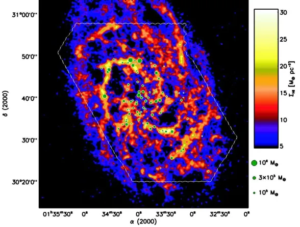
Figure 1.5: Colour image of H I 21 cm emission in M33 from Deul & van der Hulst (1987) with molecular clouds from Engargiola et. al., 2003. The areas of the molecular clouds have been scaled to represent the relative masses of the clouds. This image is taken from Engargiola et. al., 2003
1.4
Molecular clouds: Theories
The formation of GMCs can occur in essentially 3 different ways (see also reviews in Elmegreen (1990, 1996) and references therein):
- Agglomeration of smaller cloudlets through random collisions
The collisional model was first proposed by Oort (1954), and a theoretical anal-ysis followed in Field (1965). GMCs are conceived to form through the agglomeration of smaller clouds, which are in hydrodynamical equilibrium in the ISM. The clouds are more dense than the ambient ISM and therefore collisions between them are regarded as ballistic. Assuming that clouds are most likely to coalesce as a result of a collision, the mass spectrum of the clouds is dn/dM ∝ M−1.5 in equilibrium (Field & Saslaw, 1965;
Field & Hutchins, 1968; Taff & Savedoff, 1972; Handbury et al., 1977), similar to observa-tions. The long lifetime determined for these clouds (Scoville & Hersh, 1979; Kwan, 1979) corresponded with the supposed longevity of molecular clouds from observational results at the time (Section 1.4.1).
Colliding flows or a spiral shock potentially provide situations where the agglomera-tion of GMCs from molecular gas could occur (Pringle et al., 2001; Clark & Bonnell, 2006). Rather than random collisions between clumps, the clumps interact more frequently ac-cording to a potential or the Mach number of the shock. Cloud collisions subject to shear forces in a gravitational potential are found to produce a mass spectrum more similar to observations (Das & Jog, 1996). Recent simulations (Clark & Bonnell, 2006) also indicate that the mass spectrum of colliding clumpy flows produces a Salpeter type mass spectrum, consistent with star forming clumps, although slightly steeper than currently observed for molecular clouds.
- Instabilities in the ISM: Gravitational, thermal and magnetic
For a thin disk to be gravitationally stable against axisymmetric perturbations re-quires the Toomre parameter (Toomre, 1964) Qto be>1. For a gaseous disk,
Qg = κσ
πGΣ (1.3)
whereκis the epicyclic frequency,σ is the velocity dispersion and Σ is the surface density. Usually galaxies are found to have Qg ∼1 (Kennicutt, 1989; Martin & Kennicutt, 2001; Boissier et al., 2003), whilst lower values of Qg are expected to produce vigorous star for-mation (Li et al., 2005). There are 2 scenarios for gravitational collapse in spiral galaxies: In one case, transient instabilities in the gas and stars lead to simultaneous star and spiral arm formation (Goldreich & Lynden-Bell, 1965), typical of multi-arm flocculent galax-ies. The second is that gas compressed to higher densities behind a spiral shock becomes gravitationally unstable (Elmegreen, 1979; Cowie, 1980, 1981; Balbus & Cowie, 1985; Bal-bus, 1988; Elmegreen, 1994b). The latter was first proposed by Elmegreen (1979), who considered a magnetic cylinder parallel to a spiral arm. Comparisons with the observed properties of dust lanes behind shocks indicated that such a cylinder would be unstable. Subsequent analysis determined a Toomre-type parameter for a gas disk subject to a spiral potential, inclusive of the density enhancement in the spiral arms (Balbus & Cowie, 1985). The growth of density perturbations occurs in the compressed gas providing σ ≤ 7 km s−1.
The above gravitational instabilities predict the formation of 106
−107 M
com-plexes, with a regular spacing of 0.5-2 kpc along the spiral arms, assuming a sound speed of several km s−1 (Elmegreen, 1979; Balbus & Cowie, 1985; Elmegreen, 1994b). This agrees with the largest clouds observed in galaxies (Elmegreen & Elmegreen, 1983; Garcia-Burillo et al., 1993).The formation of low mass clouds from this model is unclear though. One pos-sibility is to include cooling during cloud collisions, which reduces the sound speed of the gas and thereby length scale of the collapse (Elmegreen, 1989). Many authors also discuss the condensation of ’cold’ clouds through thermal instabilities in uniform gravitationally stable gas (e.g. Field 1965; Parravano 1987).
gravitational Jeans instability (Kim et al., 2002, 2001). Theoretical analysis also concludes that gravitational collapse will dominate magnetic pressure in cloud formation (Elmegreen, 1982).
- Forced compression of the ISM by supernovae, turbulence or spiral wave shocks
Observations of bright stars situated on the edge of bubbles or arcs are often as-sociated with the triggering of star formation by supernovae or HII regions (e.g. Oey & Massey 1995; Deharveng et al. 2003; Oey et al. 2005). This star formation is often attributed to the compression of anexisting molecular cloud by shock waves from ioniza-tion fronts from OB stars (Elmegreen & Lada, 1977; Elmegreen, 1998). However giant rings and supershells formed by supernovae, which extend 100 pc or more over a galactic disk, may be able to sweep up atomic gas in the ISM to form a new generation of molec-ular clouds (McCray & Kafatos, 1987; Tenorio-Tagle & Bodenheimer, 1988; Efremov & Elmegreen, 1998). The massive shells may fragment into clouds by gravitational (McCray & Kafatos, 1987; Elmegreen, 1994a; Whitworth et al., 1994) or thermal (Koyama & Inut-suka, 2000) instabilities. Observations of the region LMC4 support this scenario, where shocks from supernovae appear to be propagating into HI clouds (Dopita et al., 1985; Efre-mov & Elmegreen, 1998) (it is also suggested that the local clouds have been triggered in a similar manner). The models for spiral structure by Mueller & Arnett (1976) and Gerola & Seiden (1978) (Chapter 4) assume that such self propagating star formation in galaxies is widespread. However the contribution of triggered molecular cloud formation is relatively unknown.
It is also conceivable that turbulent compression in the ISM results in molecular cloud formation (Vazquez-Semadeni et al., 1995; Elmegreen, 1996; Ballesteros-Paredes et al., 1999; Glover & Mac Low, 2006b). Ballesteros-Paredes et al. (1999) advocate Taurus as an example of this mechanism, since there is no evidence of triggering from supernovae, and the HI data indicates that Taurus lies between colliding flows of gas. The advantage with this scenario is that if turbulence regulates the ISM from galactic scales down to molecular cloud cores, the structure should appear self similar for each size scale, in agreement with observations (Elmegreen, 2002; Elmegreen et al., 2003).
Finally, the triggering of star formation by spiral waves follows the model of Roberts (1969) and is described in more detail in Chapter 4. The spiral triggering process is usually coupled with one of the mechanisms above; thermal (Koyama & Inutsuka, 2000) and/or Parker instabilities lead to fragmentation in the compressed gas forming clouds, whilst spiral shocks may lead to enhanced interactions between clouds (Roberts & Hausman, 1984; Scoville et al., 1986; Cowie, 1980). Star formation by spiral arm triggering has recently been modelled by Bonnell et al. (2006). These simulations show that spiral shocks can also explain the turbulent motions that are observed in GMCs, which are induced by the spiral shock on all scales simultaneously.
the content of molecular gas is high, e.g. M51 or the centres of galaxies, GMCs could form through the agglomeration of pre-existing molecular clouds. In this scenario, the ISM may be predominantly molecular (or cold HI), but GMCs are only observed where the gas has coalesced into larger structures heated by star formation (Pringle et al., 2001). However this is unlikely to occur in the outskirts of galaxies or for example, M33, where little molecular gas is thought to exist aside from GMCs (Engargiola et al., 2003). Then other processes, most commonly gravitational/magnetic instabilities or compression from shocks (Shu et al., 1972; Aannestad, 1973; Hollenbach & McKee, 1979; Koyama & Inut-suka, 2000; Bergin et al., 2004) must be required to convert atomic to molecular gas. An alternative view is that the formation process is unique, and the molecular content of the gas is determined by the pressure of the ISM (Blitz & Rosolowsky, 2004).
1.4.1 Lifetimes of molecular clouds
It was previously believed that the lifetimes of GMCs were relatively long, of the order 100 Myr. This was based on early observations of CO which did not show any spiral structure, implying that molecular clouds must last for at least the interarm crossing time. Furthermore the star formation rate appears too low compared with the Galactic mass of H2 unless the formation timescale is sufficiently long (Zuckerman & Evans, 1974).
However recent observations have implied that the onset of star formation is much more rapid, occurring over a dynamical timescale of the cloud (Elmegreen, 2000; Hartmann et al., 2001). Elmegreen notes that the distribution of stars appears to be ’frozen out’ in the gas, resembling a hierarchical system of clusters embedded within the cloud, and preserving the turbulent conditions of the gas in which star formation takes place. The spread of ages in the stellar cluster is small, of order a dynamical time, and the separation of the clusters correspondingly small, and finally, as noted in the introduction, the fraction of clouds without star formation is very low. Then the total lifetime of a GMC, including disruption, is ∼3×10⁷ yr (Elmegreen, 2000; Pringle et al., 2001). In this hypothesis, the low galactic star formation rate is explained by the low star forming efficiency, with only a small fraction gas in a molecular cloud undergoing collapse at any particular time, due to the highly structured, turbulent nature of molecular clouds.
The consequences of a shorter molecular cloud lifetime have been expanded by Pringle et al. (2001). They analyse shock formation of H2 and find that in order for such
rapid formation of molecular clouds to occur, the pre-shock gas must be relatively dense,
∼102cm−3. This is sufficiently dense that the pre-shock gas will already be predominantly
1.5
Previous numerical work
The simulations presented here consider the hydrodynamics of the gas and the response of the gas to a spiral potential. Without instabilities from self gravity or cooling, the formation of discrete clouds in the spiral arms at first seems unlikely. Calculations by Dwarkadas & Balbus (1996) showed that a gas flow subject to a spiral potential is stable against purely hydrodynamical i.e. Rayleigh-Taylor or Kelvin-Helmholtz type instabilities, for the parameters chosen in their model. Thus one would predict continuous spiral arms traversing the disk roughly coincident with the minimum of the potential (Roberts, 1969). Likewise several simulations of gas flow in a spiral potential show smooth symmetirc spiral arms (Patsis et al., 1997; Chakrabarti et al., 2003), although the branching of spiral arms occurs at radii corresponding with resonances in the disk. The 2D disk simulations of Wada & Koda (2004) and Gittins (2004) do show structure along the spiral arms, although this structure is not particularly extensive. Spurs form perpendicular to the arms, but the length of these is much less than the interarm width.
These previous simulations of gaseous disks all assume a single phase, isothermal medium, generally in a non self-gravitating disk without magnetic fields. The sound speed is usually 10 km s−1 corresponding to the warm neutral phase of the ISM. G´omez
& Cox (2002) include magnetic fields, but the large scale structure is similar to purely hydrodynamic calculations (e.g. those of 104 K in Chapter 4). Other numerical analysis
of disks has investigated the location of the spiral shock (Gittins & Clarke, 2004), and the dependence of the spiral morphology on the pattern speed of the potential and sound speed of the gas (Slyz et al., 2003). Kim et al. (2002) take a section of the disk and include a spiral potential with periodic boundary conditions, magnetic fields and self gravity. Their results show the collapse of gas in spiral arms due to gravitational and Parker instabilities, and the formation of prominent spurs perpendicular to the spiral arms (Kim & Ostriker, 2002). The ISM is again assumed to be isothermal with a similar sound speed to the simulations described above. Bonnell et al. (2006) model the passage of a region of cold gas through a spiral arm, the formation of GMCs and the triggering of star formation. Although gravitational instabilities induce star formation in the gas, they find that the dynamics of the gas are primarily dependent on the clumpy initial distribution of the ISM and the spiral shock.
recently produced models of the ISM which include the transition of atomic to molecular hydrogen.
The localised ISM simulations generally ignore galactic scale processes such as spiral shocks or rotational shear. Simulations to include a comprehensive treatment of the ISM on galactic scales have been performed in 2D (Wada & Norman, 1999, 2001) and recently 3D (Tasker & Bryan, 2006). These calculations do not include a spiral potential - instead gravitational instabilities induce flocculent structure. Gravitational instabilities and cool-ing of the ISM contribute to a cold (≤100 K) phase of gas associated with molecular cloud formation (Wada & Norman, 1999). Star formation is predicted where the Toomre insta-bility criterion is satisfied in the disk (Li et al., 2005; Tasker & Bryan, 2006). The inclusion of feedback, whilst adding a hot phase to the ISM does not appear to be necessary for complex structure to occur in the plane of the disk (Wada & Norman, 2001). Simulations of supernovae in a localised region of a galactic disk (de Avillez & Breitschwerdt, 2005) show that supernovae are however required to reproduce the vertical structure of the disk and can compress gas into high-latitude clouds, above the plane of the disk.
As yet, there are no simulations of grand design spirals with a detailed treatment of the ISM or stellar energy feedback. Simulations which include magnetic fields and self gravity are now commencing. As will become apparent in this thesis, the dynamics of the spiral shock alone are complicated, without including additional physics. However some discussion of expected future work is included in Chapter 7.
1.6
Outline of Thesis
This thesis describes numerical models of the formation of molecular clouds in spiral galaxies. Although the simulations presented here represent a simple model, of a gaseous disk subject to a spiral potential, the results shown in this thesis indicate that discrete clouds of gas with a high degree of structure can form in the spiral arms. This was a surprising outcome and not expected before the simulations commenced. This thesis attempts to analyse their formation, structure and correspondence with observations. The conditions required for the formation of these clouds are discussed, and why they have not been reported in other models or simulations.
Chapter 2 describes the Smoothed Particle Hydrodynamics (SPH) code used to perform these simulations. Various tests are performed to establish how well SPH, and recently suggested modifications to SPH, are able to model shocks. Chapter 3 follows on from Bonnell et al. (2006), who propose the generation of a velocity dispersion in clumpy shocks. This chapter analyses shocks using different initial gas distributions to determine the velocity dispersion relation of the gas. The motions of the gas are compared with the usual view of turbulence in molecular clouds.
CHAPTER 2
Smoothed Particle Hydrodynamics
The simulations described in this thesis use the Smoothed Particle Hydrodynamics method (SPH). SPH is a 3D Lagrangian hydrodynamics code that has been successfully applied to a variety of astrophysical problems. An advantage of SPH is that it is highly adapt-able, and computational simulations can be set up with any distribution of particles, over many scales. As the code is Lagrangian, SPH uses an interpolation method to determine physical quantities such as density and pressure. The code has been subject to major modifications since the version of Benz (1990). In particular particles now evolve with individual timesteps and gravitational forces are calculated using a hierarchical tree (Benz et al., 1990). Recent modifications include magnetic fields (Price & Monaghan, 2004, 2005) and radiative transfer (Whitehouse & Bate, 2004; Stamatellos & Whitworth, 2005; Whitehouse & Bate, 2006; Viau et al., 2006), but these are beyond the scope of this thesis.
A major criticism of SPH is the handling of shocks. This chapter includes a discus-sion of 2 methods to improve the treatment of shocks by SPH and their implementation. These methods are applied to simple shock tube tests and the results compared with the original SPH code and analytic solutions. Since much of this thesis concerns spiral density wave shocks, the ability of SPH to handle shocks is highly relevant.
2.1
The SPH equations
SPH was developed independently by Lucy (1977) and Gingold & Monaghan (1977). The derivation of the SPH equations is described in previous papers (Monaghan, 1982; Benz, 1990) and is not included here. However the main equations and components of the code are introduced below.
Any continuous function f(r), defined over a space V, can be approximated by a smoothed function
< f(r)>=
Z
V
W(r−r0,h)f(r0)dr0. (2.1)
The function W is known as the kernel and satisfies the following properties:
Z
V
W(r,h)dr0 = 1 and (2.2)
The parameter h, the smoothing length, represents the width of the kernel and thereby determines the degree of space over which the functionfis smoothed. By choosing a kernel highly peaked at r = r0, < f(r) > approximates f(r0) to second order in h. A variety of kernels have been tested in SPH, but typically a spline kernel is used (Monaghan & Lattanzio, 1985).
SPH is a particulate code and so uses a discrete form for the smoothing function. For N particles, Equation 2.1 becomes
< f(r)>= N
X
j=1
mj
ρ(rj)
f(rj)W(|r−rj|,h). (2.4)
This is the central equation in SPH, sincef can be replaced by any desired variable. For example, insertingf(r) =ρ(r) gives the density
< ρ(r)>= N
X
j=1
mjW(|r−rj|,h). (2.5)
The format of Equation 2.4 also allows the gradient and divergence of variables to be written as smoothed quantities. The continuity equation is automatically satisfied through Equation 2.5, and the SPH momentum equation can be determined by applying Equation 2.4 to the Eulerian momentum equation. Hence the momentum equation becomes
dvi dt =−
X
j6=i mj
P
i ρ2
i +Pj
ρ2
j + Πij
OiWij (2.6)
where Πij is the artificial viscosity and Oi denotes gradient with respect to particle i. The viscosity term allows for an artificial treatment of shocks in SPH and is described further in Section 2.2. The SPH equations for energy conservation, radiation transport and Poisson’s equation are described in Benz (1990). These are not applied in this work though since the gas is assumed to be isothermal and non self-gravitating.
In addition to the physical variables, SPH particles also exhibit individual smoothing lengths and timesteps. This allows greater flexibility with the code, as typical length scales and densities can vary without the computational time increasing extensively. The smoothing length for each particle can be scaled to vary with the density, as
h=h0
ρ0
ρ
1/3
, (2.7)
so the number of neighbours of each particle remains similar (usually ∼ 50). Following
Benz (1990), the time derivative of the smoothing length is
dh dt =−
1 3
h ρ
dρ
dt. (2.8)
Then using the continuity equation to replace dρ/dt gives
dhi dt =
1
3hO.vi. (2.9)
2.2
SPH and shocks
One of the difficulties in SPH, compared to other methods, is the handling of shocks. In the derived SPH equations there is no dissipative process to convert kinetic to thermal energy when gas shocks. This leads to the problem of particle penetration, where colliding streams of particles are able to pass through each other. Consequently, variables such as the velocity may become multivalued where the gas shocks. To remove this problem, an artificial viscosity term is introduced into the SPH momentum equations which acts like a pressure term.
The artificial viscosity commonly used (Monaghan & Gingold, 1983) is
Πij=
−αhvij·rij ¯
ρij|rij|2
¯
cij−βhv|rijij·|r2ij
ifvij·rij<0
0 otherwise
(2.10)
where h is the smoothing length, vij = vj −vi, rij = rj −ri, ¯cij = (ci +cj)/2, and ¯
ρij= (ρi+ρj)/2. This is based on a bulk velocity term and the von Neumann-Richtmyer artificial pressure:
bulk Π =−αρlcO·v
von Neumann-Richtmyer Π =−βρl2(
O·v)2
Typically β = 2α in SPH simulations, hence the deceleration in Equation 2.6 due to the viscosity is determined by the constant α. Tests (Bate, 1985) indicate that α & 0.8 is required to prevent inter-particle penetration and accurately reproduce a Mach 2 shock, but larger viscosities are required for stronger shocks.
Values of α = 1 and β = 2 are shown to be adequate for most SPH simulations (Monaghan & Gingold, 1983). Very high viscosities are not desirable as the shocks will be too dissipative. For high Mach number shocks however, this artificial viscosity is not always sufficient to produce sharp accurate shocks. Instead shocks show smearing as particles are able to penetrate through the shock. Several suggestions have been made to improve the accuracy of modelling shocks in SPH. The 3 main possibilities considered are:
- allowing the viscosity to vary with time, and increase to larger values if required
- XSPH, which uses a smoothed velocity to update particle positions and prevent particle penetration
- Gudonov SPH, which uses a Riemann solver to include the analytical results of shock tube tests
The first two of these improvements are described next.
2.2.1 Viscosity switch
a shock and then decay. The parameterα evolves with time according to
dα dt =−
α−α∗
τ +S. (2.11)
The first term on the right is a decay term which allows the viscosity to return toα∗ over
a time period τ, dependant on the sound speed and smoothing length. The parameter α∗ is set to 0.1, which represents the default viscosity of the particles away from shocks. The second term on the right is a source term, chosen to increase the viscosity as a particle approaches a shock. Morris & Monaghan (1997) use the velocity divergence, S =max(−O·v,0), so overall Equation 2.11 becomes
dα
dt =−(α−α
∗)C1c
h +max(−O·v,0). (2.12)
C1 is a constant, set to 0.2 for α to decay back to α∗ over ∼ 2 smoothing lengths (see
Morris & Monaghan (1997)) andc is the sound speed.
2.2.2 XSPH
XSPH was suggested by Monaghan (1989, 2002) to prevent particle penetration by velocity smoothing. Monaghan (1989) defines the smoothed velocity bvi as the average over the velocities of the neighbouring particles:
b
vi =vi+
X
j6=i
mj
ρj
vijWij. (2.13)
This is equivalent to Equation 2.4, where f is replaced by v. The parameter 0 < < 1 determines the degree of velocity smoothing, = 0 for SPH and = 1 for full XSPH. A value of= 0.5 is suggested in Monaghan (1989).
The smoothed velocity is then used to update the particles positions instead of the individual particle velocities, according to
dr
dt =vbi. (2.14)
Then, for example, the smoothed velocity in the centre of a shock is determined by the average of the incoming velocities and will be 0, as required, and the velocity cannot become multivalued. It can further be shown (Monaghan, 2002) that XSPH conserves angular and linear momentum, and is non-dissipative.
2.3
Shock tube tests
Shock tube tests are carried out for SPH and these modified versions of SPH. To summa-rize, the different codes investigated are
- SPH: standard version of SPH
Figure 2.1: The different particle distributions used: cubic lattice (left), unaligned lattice (centre) and offset distribution (right).
- αSPH: particles have individual values ofα
- αXPSH: uses both XSPH andαSPH
The notation of the latter two is not standard, but is used here for convenience.
The shock tests themselves consist of two colliding flows and are set up with ve-locities allocated in the x direction, vx = v0 for x <0 and vx =−v0 for x > 0. All the
tests in this chapter are in 3D, so the shock occurs in the yz plane. These tests use 3 different particle distributions - the unaligned lattice, cubic lattice and offset distribution (Figure 2.1). The offset distribution is used primarily to test for particle penetration, since this will be the worst case scenario, although unlikely to occur in real simulations. The unaligned lattice is more likely to resemble simulations. Reflective (cubic lattice) or periodic (unaligned lattice and offset distribution) boundary conditions are used, so ghost particles continue the distributions of particles in Figure 2.1.
The α andβ values are set as fixed parameters in SPH and XSPH, or as arrays for individual particles in αSPH andαXSPH. Here, as common in SPH, theβ parameter is set as twice α. The viscosity is described in terms ofα, although as shown by Bate (1985), the bulk term determined by β is of more consequence in shock simulations than the α term in Equation 2.10. ForαSPH andαXSPH, the initial array ofαis set to 0.1, the same as the minimum viscosity in the decay term in equation 2.12. Since the viscosity increases relatively quickly as gas approaches a shock, the initial value of αis not expected to be of particular importance. Boundary particles are also allocated individual values of α.
2.4
Particle penetration
The problem of particle penetration is investigated for the 4 different codes, although primarily to investigate the difference of the XSPH velocity smoothing included specifically to prevent this problem (Monaghan, 1989). Tests are first carried out with an offset distribution, for which particle penetration will be most problematic. All the shocks in this section are isothermal, but particle penetration generally occurs less for adiabatic shocks (Bate, 1985). The particles take initial velocities ofv0 = 1cs. For the early stages of the shock, which are used for these results, the Mach number is 2. The particles are initially distributed in a cube −4< x <4,−1< y <1,−1< z <1 and the resolution of the grid is 8 particles per unit length.
Figure 2.2 shows the distribution of particles over the xy plane, comparing XSPH and codes with different artificial viscosity parameter α. For an ideal shock, the shock location lies atx = 0 and particles should stop as they reach the yz plane at x= 0. The top two figures show results where the artificial viscosity is switched off, i.e. α = 0. For standard SPH, the opposing streams of particles fully penetrate through each other. By contrast, the particles are completely stopped on their approach to the shock front for full XSPH (where the XSPH parameter is set to 1), even though there is no artificial viscosity. The further plots show results when α = 1, since this is typically used in SPH calculations, and the αSPH code. There is very little particle penetration for the α = 1 case, with only one layer of particles penetrating the opposing stream. The fourth diagram shows the particle distribution for theαSPH code, which produces a higher degree of particle penetration. The reason for this can be seen from looking at the values of α for the particles. As shown in Figure 2.3, the value of α increases to a maximum of 0.8, lower than the SPH run and insufficient to completely prevent particle penetration.
2.4.1 Particle penetration with different Mach number shocks
Shock tests are performed to investigate the degree of particle penetration for different Mach number isothermal shocks. These tests use the 4 different codes, SPH XSPH,αSPH and αXSPH. For the XSPH andαXSPH codes, the XSPH parameter (in Equation 2.13) is set to 0.5, as suggested (Monaghan, 1989). For theαSPH andαXSPH tests, the variable α is initially set to 0.1 for all the particles, whilst the standard viscosity α= 1 is used for SPH and XSPH. Again the offset lattice distribution of particles is used, of dimensions
−4 < x < 4, −1 < y < 1 and −1 < z < 1. Previous analysis (Bate, 1985) shows that particle interpenetration is not halted for isothermal shocks of Mach numbers ≥4 for the offset distribution. The particle penetration is thus quantified by recording the number of layers of particles which cross into the opposing stream of particles, and compared for the different codes at a certain time. An example of a case where there are 4 layers of penetration is shown in Figure 2.4. A smaller number of layers indicates that less particle penetration is occurring and the shock is more accurately treated by the code.
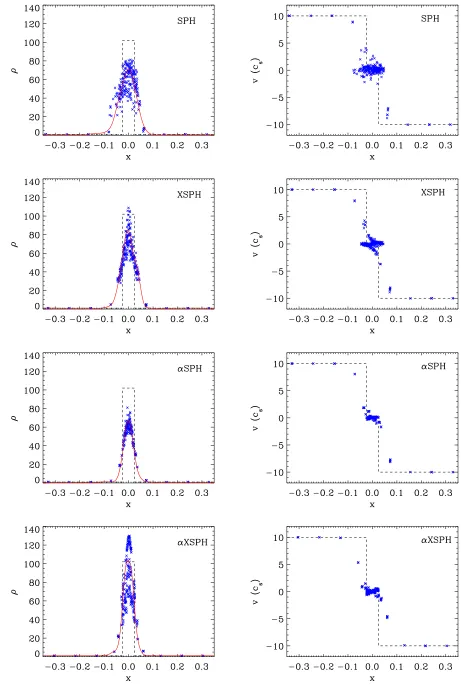
Figure 2.2: Comparison of particle penetration for the SPH, XSPH andαSPH codes. The SPH (top left) and XSPH (top right) examples do not use any artificial viscosity terms. Also shown is SPH with α = 1 (bottom left) and the αSPH code (bottom right). The figures are shown at t= 1/v0 and the initial velocity is v0 = 1cs.
[image:34.612.255.429.498.660.2]Figure 2.4: Example showing 4 layers of particle interpenetration. This is taken from an XSPH simulation with Mach number 10. The time of the simulation ist= 2/v0
v0 No. layers att= 2/v0 No. layers at t= 4/v0
SPH XSPH αSPH αXSPH SPH XSPH αSPH αXSPH
1 1 0 2 0 1 0 2 0
2 3 2 3 2 9 5 8 4
5 5 4 5 3 10 8 9 7
10 5 4 5 3 10 9 9 7
20 5 4 5 4 10 9 10 8
Table 2.1: Table showing the number of particles for each layer which cross into the op-posing stream for SPH, XSPH,αSPH andαXSPH codes. The offset particles distribution is used, for different Mach number shocks.
v0 = 2cs shocks, penetration is halted by t= 4/v0. However for the higher Mach number
shocks further penetration is still ongoing.
Figure 2.5 shows the growth of α with time for the Mach 2, 4 and 40 shocks cor-responding to the tests of αSPH and αXSPH in Table 2.1. Again the time is scaled so that for each initial velocity (v0), the number of particles reaching the shock is the same.
The maximum value of αpeaks at approximately 0.8 and 1.4 for the Mach 2 and 4 shocks respectively. Although not plotted, α peaks at ∼ 2.3 and 2.6 for the Mach 10 and 20 shocks. The value of α does not stabilise until after t = 4/v0 for the Mach 40 shock,
eventually reaching a maximum of∼ 3.5. The values of α obtained for the αXSPH code are generally greater than for αSPH. This is because the increase in viscosity is depen-dent on a source term, proportional to the divergence of the velocity. XSPH works by smoothing the velocities of the incoming particles and thus the particles decelerate more (in comparison to standard SPH) as they approach the shock. Consequently the source term is larger when the XSPH is included.
Figure 2.5: Plot showing values of the maximum value ofα with time, obtained for the αSPH and αXSPH codes, using results from the same simulations as given in Table 1. Lines are given for the αSPH code with v0 = 1cs (black), v0 = 2cs (green), v0 = 20cs (magenta) and the αXSPH code with v0 = 1cs (red), v0 = 2cs (blue) and v0 = 20cs (cyan).
unlike XSPH, the viscosity switch was not introduced explicitly to prevent particle pene-tration. The viscosity parameter α increases to 0.8, when v0 =cs, slightly less than the
standard value of 1, but sufficient to prevent most particle penetration. For the highest Mach numbers, the increase in particle penetration at t = 2/v0 is likely due to α not
increasing sufficiently quickly to prevent penetration. However α can be set to a higher value initially, which would ensure that αSPH would perform at least as well as SPH for low Mach number shocks.
The αXSPH code is most effective for high Mach number shocks, reducing parti-cle penetration by 20%. However Table 2.1 does not fully represent the effectiveness of αXSPH, since the distance of particles travelling through the shock into the opposing stream was greatly reduced, e.g. forv0= 10, particles had reached distances of x=±0.08
into the opposing streams for αXSPH, half that of standard SPH and some improvement on XSPH orαSPH alone.
2.4.2 Increasing the source term
For the higher Mach number shocks, α does not peak until a later time, after several particles have entered the shock (t= 2/v0 corresponds to 9 particles entering the shock).
Increase in No. layers att= 2/v0 No. layers att= 4/v0
source term αSPH αXSPH αSPH αXSPH
1 5 3 9 7
2 4 2 8 7
4 2 1 6 4
10 1 0 3 2
Table 2.2: Table showing the number of particles for each layer which cross into the opposing stream for αSPH and αXSPH codes. The offset particles distribution is used, and v0=5csfor all the shocks. The source term (Equation 2.11) is increased by a constant factor.
the source term is increased in Table 2.2, whenv0= 5cs. In each case, the maximum value
ofαincreases by the same factor as the source term is increased. As indicated by Table 2.2, increasing the source term greatly reduces the degree of penetration, so that if the source term is increased by a factor of 10, there is very little penetration. The disadvantage is that the width of the shock increases, since α becomes high earlier as particles approach the shock, and consequently the density of the shock is underestimated. When the source term is doubled, there is very little difference in the densities. For an increase in the source term by a factor of 4, the density decreases by 15%, and when the source term is increased by a factor of 10, the density in the shock is reduced by over one third.
2.4.3 Particle penetration dependence on the XSPH parameter
The XSPH velocity equation (Equation 2.13) includes the variable parameter which can be varied to give different degrees of smoothing. The number of layers of penetrating particles is shown in Table 2.3, when v0 = cs and v0 = 5cs (for the XSPH code). The
number of particles is given for the case where there is no viscosity (α = 0) and where the standard viscosity α = 1 is used. The degree of particle penetration shows a small decrease for larger values ofwhenα= 1. A similar dependence onis likely forαXSPH, if an initial α of 1 is applied. The suggested value of= 0.5 in XSPH is just sufficient to prevent penetration for the v= 1cs case (Table 2.1). As expected, the effect of changing is much more significant when there is no viscosity, since the ability of the gas to shock depends solely on the XSPH term.
2.4.4 Varying the initial distribution
No. of layers (v0=cs) No. of layers (v0 = 5cs) α= 0 α= 1 α= 0 α= 1
0.0 9 1 9 4
0.2 7 1 8 4
0.4 4 1 8 4
0.6 2 0 6 4
0.8 1 0 5 3
1.0 0 0 4 3
Table 2.3: The number of particles crossing into the opposing stream is tabulated for different values of . All these simulations use the XSPH code with the offset lattice distribution. Two different initial velocities are compared, v = 1cs and v0 = 5cs. The effectiveness of XSPH is shown for the case where there is no artificial viscosity, and where α = 1.
Table 2.4 indicates that particle interpenetration is minimal for the unaligned lattice. For most of the tests, 0 or 1 particles pass the shock boundary, and in all cases, none of the particles continue to pass through the shock, as happened with the offset distribution. The standard SPH code allows a few particles to penetrate the shock boundary. The XSPH and variableα codes reduce this. In a couple of cases, the first layer of particles initially passed across the shock boundary (and thereby past the first layer of particles immediately above or below for the unaligned lattice), but subsequently pass back as pressure forces act on the shocked region. Longer tests for the Mach 40 shock with αSPH, XSPH and αXSPH showed no further penetration than indicated in Table 2.4.
Tests were also carried out for the cubic lattice, but no particle interpenetration occurred for the Mach 40 shock. This is not surprising since this is the optimum distribu-tion for preventing particle interpenetradistribu-tion. Similar tests by Bate (1985) showed that for shocks of Mach 10 or less, there is no particle interpenetration for the unaligned or cubic lattice with SPH for viscosity parameters similar to those applied here.
The values of α were also recorded for the runs with different distributions. As would be expected, there is minimal variation of α for the different distributions. Figure 2.6 shows the variation ofαwith time for a Mach 10 shock, for the 3 different distributions.
Simulations at higher resolution are also used to investigate whether the resolution has any effect on the values of α, or particle interpenetration. Figure 2.7 shows the variation of α with time for different resolution tests. These tests use the unaligned lattice and take v0 = 5cs. Figure 2.7 indicates that the peak value ofα does not depend on the resolution The only difference is that for the higher resolution runs, α increases slightly more rapidly, which may help to prevent penetration. However, for these tests, no difference in the degree of particle penetration was found.
2.5
Comparison with analytical solutions
v0 No. layers att= 2/v0 No. layers at t= 4/v0
SPH XSPH αSPH αXSPH SPH XSPH αSPH αXSPH
1 0 0 1 0 0 0 1 0
2 1 0 1 0 1 0 1 0
5 1 0 1 1 1 1 1 1
10 1 0 1 1 2 1 1 0
20 1 0 1 1 3 1 1 0
Table 2.4: Table showing the number of particles for each layer which cross into the oppos-ing stream for SPH, XSPH,αSPH andαXSPH codes. The unaligned particle distribution is used, for different Mach number shocks.
Figure 2.6: Plot showing the variation of the maximum value of α with time for the unaligned lattice (solid), cubic lattice (dotted) and offset (dashed) distributions. All shocks are Mach 10 and use the αSPH code.