PERSION AND INTERACTION PROPERTIES IN COMPOSITE
STRUCTURES
R.K. Apalowo, T. Ampatzidis, D. Chronopoulos
University of Nottingham, Institute for Aerospace Technology & Composites Research Group, Nottingham, UK email: [email protected]
M. Ichchou
Ecole Centrale de Lyon, 36 Avenue Guy de Collongue, 69130 Ecully, France
Y. Essa and F.M. De La Escalera
Aernnova Engineering Solutions Iberica, Madrid, Spain
Composite structures are widely used for aerospace and automotive applications. These oper-ate within a broad temperature range varying between -100◦C to 200◦C for launch vehicles and -60◦C to +50◦C for aircraft and automotive vehicles. Hereby, the sensitivity of the wave prop-agation and interaction properties of a composite structure to the ambient flight temperature is investigated. A wave finite element (WFE) and finite element (FE) based computational method is presented by which the temperature dependent wave dispersion characteristics and interaction phenomenon in a composite structures can be predicted. Initially, the temperature dependent me-chanical properties of the panel in the range of -100◦C to 150◦C are measured experimentally using the Thermal Mechanical Analysis (TMA). Temperature dependent wave dispersion charac-teristics of each waveguide of the structural system, which is discretised as a system of a number of waveguides joined by a coupling element, is calculated using the WFE approach. The wave scattering properties, as a function of temperature, is determined by coupling the WFE wave char-acteristics models of the waveguides with the full FE modelling of the coupling element on which defect is included. Numerical case studies are exhibited for two waveguides coupled through a coupling element.
Keywords: composite structure, temperature dependency, wave dispersion characteristics, wave finite element, wave scattering coefficients.
1.
Introduction
Aerospace and automotive structures operate within varying temperature range, which is typically broad (between -100◦C to 200◦C) for launch vehicles but quite narrow (-60◦C to +50◦C) for aircraft and automotive structures. A substantial amount of research has been conducted on the wave inter-action properties of layered structures but a very little has been on the effect of temperature on the properties. Hereby, an attempt is made to predict the dependency of wave interaction coefficients of a composite structure on ambient flight temperature.
The numerical analysis of wave propagation within periodic structure is introduced in [6], applied to two dimensional media in [7] and extended to formulate the wave finite element (WFE) method in [8]. The WFE has recently found application in predicting the vibroacoustic and dynamic properties of composite panels and shells [9, 10, 11, 12, 13, 14, 15], with pressurized shells [23, 20] and complex periodic structures [24, 16, 17] having been investigated. The variability of acoustic transmission through layered structures [22, 21], as well as wave steering effects in anisotropic composites [19] have been modelled through the same methodology.
The main novelty of this article is to exhibit the impact of temperature dependent parameters on the wave scattering coefficients of composite structures. The mechanical characteristics of an orthotropic sandwich panel comprising carbon epoxy facesheets and a honeycomb core are experimentally mea-sured using a Thermal Mechanical Analysis (TMA) configuration. In Sec.2 the thermomechanical characteristics of the composite panel is presented. The WFE computational scheme for the numer-ical calculation of wave propagation and interaction properties are respectively presented in sections 3 and 4. In Sec.5 numerical results are discussed. Conclusions are drawn in Sec.6.
2.
Measurement of the thermomechanical characteristics
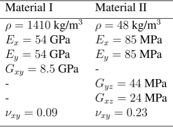
[image:2.595.212.384.427.554.2]The temperature dependent mechanical properties of an orthotropic sandwich panel is experimen-tally determined using a TMA configuration. The mechanical characteristics of the panel, consisting facesheets (material I) made of a 1 mm thick carbon epoxy composite comprising of four layers of 1-1 twilled weaves and a core (material II) made of an orthotropic 12.7 mm thick Nomex honeycomb material, at 20◦C is presented in Table 1.
Table 1: Nominal mechanical properties of the sandwich panel constituents at 20◦C
Material I Material II
ρ= 1410kg/m3 ρ= 48kg/m3
Ex = 54GPa Ex = 85MPa
Ey = 54GPa Ey = 85MPa
Gxy = 8.5GPa
-- Gyz = 44MPa
- Gxz = 24MPa
νxy = 0.09 νxy = 0.23
Measurements are made at a temperature range of -100◦C to 160◦C. A 0.1% deformation is applied to the panel for all the TMA measurements. Dissipation of the material (measured as tanδ) is determined as the ratio of the loss modulus to the storage modulus whereδis the phase lag between stress and strain.
Temperature dependent elastic modulus is determined through a longitudinal traction of the facesheet of the panel (Fig. 1a).
In order to measure the temperature dependent shear modulus, shear deformation of the honey-comb core is conducted (Fig. 1b). Traction forces are applied to opposite facesheets of the panel, allowing for shear deformation of the core.
The measured elastic (Fig. 2a) and shear (Fig. 2b) moduli decrease slightly while their corre-sponding material dissipation increases slightly with respect to temperature until 90◦C. Thereafter, the resin included in the panel enters its glass transition temperatureTg.
High peak is observed for the dissipation in this range, while moduli decrease by about 45%. After theTg, the moduli decrease with a steady rate while the dissipation after a short decrease starts
(a) Facesheet traction (b) Core shear deformation
Figure 1: Configuration of a segment of the panel in the TMA machine
Temperature (°C)
-100 -50 0 50 100 150 200
Elastic modulus (10
10
Pa)
0 1 2 3 4 5 6
damping loss factor
0 0.02 0.04 0.06 0.08 0.1 0.12 0.14 0.16 0.18 0.2
(a) Elastic modulus and corresponding dissi-pation
Temperature (°C)
-100 -50 0 50 100 150 200
Shear modulus (10
7Pa)
2 2.5 3 3.5 4 4.5 5
damping loss factor
0 0.01 0.02 0.03 0.04 0.05 0.06 0.07 0.08 0.09 0.1
[image:3.595.74.424.240.353.2](b) Shear modulus and corresponding dissi-pation
Figure 2: Experimentally measured temperature dependent moduli (-) and corresponding dissipation (· · ·) of the sandwich panel
3.
Wave propagation in an arbitrarily layered structure by WFE method
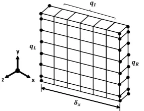
Linear elastic wave propagation is considered in thexdirection of the arbitrarily layered structural waveguide (Fig. 3). The problem is condensed using a transfer matrix approach [8].
ࡸ
ࡾ
ࡵ
ࢾ࢞
LJ
dž nj
Figure 3: WFE modelled waveguide with left and right side nodes bullet marked. Range of interior nodes also illustrated
The frequency and temperature dependent Dynamic Stiffness Matrix (DSM) (D(ω, T) = K(ω, T)−
ω2M(ω) +iωC(ω, T)) of the waveguide’s periodic segment can be partitioned with regards to its left and right sides, and internal DoFs. The WFE approach eliminates internal nodes DoFs by combining periodic segment theory with FE. Hence, the system is condensed to only left and right nodes DoFs with time harmonic behaviour expressed as
DLL DLR DRL DRR
qL qR
=
fL fR
[image:3.595.228.371.515.625.2]
withq andf the displacement and forcing vectors respectively, and subscriptsL andR the left and right nodal DoFs respectively.
Assume no external force is applied, the displacement continuity and force equilibrium conditions relate the displacements and forces at the interface of two consecutive periodic segmentssands+ 1
as
qL(s+1)
fL(s+1)
=T
qL(s)
fL(s)
(2)
where
T =
−D−LR1DLL D−LR1
−DRL+DRRDLR−1DLL −DRRD−LR1
(3)
is the symplectic transfer matrix.
The propagation constant γ = e−ikδx of the wave relates the right and left nodal displacements
and forces asqR(s) =γqL(s)andfR(s)=−γfL(s). This is combined with the transfer matrix equation to obtain the free wave propagation eigenproblem
γ
qL(s)
fL(s)
=T
qL(s)
fL(s)
(4)
whose eigenvalues and eigenvectors solution sets provide a comprehensive description of the propa-gation constants and the wave mode shapes for each of the elastic waves propagating in the structural waveguide at a specified frequency and temperature.
4.
Elastic wave interaction with structural damage
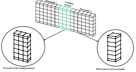
Consider two waveguides connected through a coupling joint (Fig. 4). Each waveguide is WFE modelled, while the joint is fully FE modelled and can contain damage, geometric or material incon-sistencies.
[image:4.595.187.410.486.604.2]FE model of the coupling element WFE model of each waveguide
Figure 4: Caption of a system as two waveguides connected through a coupling joint
The wavemodes obtained through the WFE scheme, at each frequency and temperature, for each waveguide can be grouped as
Φ=
Φqinc Φqref Φfinc Φfref
(5)
whereincandref denote the positive and negative going waves respectively. The modes of the two waveguides in the system can be grouped as
Ψqinc=
Φq1inc 0
0 Φq2inc
with similar expressions forΨqref, Ψfinc andΨfref. Assuming modal decomposition, the physical
domain can be converted to the wave domain as
qL
fL
=Φ
Qinc Qref
(7)
whereQdenotes the amplitudes of the wave modes.
Condensing the non-interface DoFs, the DSM of the joint can be expressed as
D∗C =Dii−DinD−nn1Dni (8)
where subscripticorresponds to the interface DoFs andnthe non-interface DoFs. Applying displace-ment continuity and equilibrium of forces at the connecting interfaces, the scattering matrixSof the joint, whose partitions relate the amplitudes of the incident and scattered waves, can be expressed as
Q1ref
Q2ref
=S
Q1inc
Q2inc
(9)
where
S=−[Ψfref −D∗CΨqref]−1[Ψfinc−D∗CΨqinc] (10)
with diagonal elements being the reflection coefficients and off diagonal the transmission coefficients of the waves.
5.
Numerical case studies
The computational scheme exhibited above is applied on two numerical case examples: a sand-wich rod, and two sandsand-wich laminates connected through a laminate joint. Calculations are made at five different temperatures, -100, 90, 110 and 150◦C for the composite laminate example and at four different temperatures, -110, 90, 110 and 150◦C for the rod example.
5.1 A sandwich rod
Consider a rod consisting of a honeycomb foam core (Material II) sandwiched between two carbon epoxy facesheets (Material I) as shown in Fig. 5. The rod is subdivided into two waveguides and a coupling joint of cross-sectional areasA1 = A2 = AJ = 0.003m2, lengths L1 = L2 = 0.2m and
LJ = 0.003m. Wave interaction due to material inhomogeneity of the rod is considered.
ݔ ܽ
ଵା ܽଶା
[image:5.595.201.395.578.626.2]ܽଵି
Figure 5: Caption of the sandwich rod
By modelling the two waveguides through the WFE approach, it can be found that a single wave propagates within the rod from 0 to approximately 700 kHz. The results are compared against the analytical results presented in [25].
Frequency [105Hz]
0 1 2 3 4 5 6 7 8
Wavenumber [1/m]
0 200 400 600 800 1000 1200 1400
(a) Wavenumber
Frequency [105Hz]
0 0.5 1 1.5 2 2.5 3 3.5 4
Wave interaction coefficient
0 0.05 0.1 0.15 0.2 0.25
[image:6.595.84.516.55.194.2](b) Reflection coefficient
Figure 6: Comparison between the WFEM and the analytical predicted results for the sandwich rod: analytical -110◦C (+), 90◦C (), 110◦C (◦), 150◦C (), WFEM -110◦C (. . .), 90◦C (- -), 110◦C (-.-), 150◦C (-)
FE discretization error which increases with frequency [8]. It is also shown that a little difference in wavenumber is observed between -100 to 90◦C, high difference of about 25% between 90 and 110◦C and beyond 110◦C, the wavenumber increases at a steady rate. It is therefore evident that the difference will be much greater at larger temperature ranges beyond Tg.
Numerical and analytical results for the wave interaction coefficients are presented in Fig. 6b. A good agreement is observed between the two sets of results. The results also show a proportional increase in the interaction coefficient with respect to temperature until the glass transition temperature (110◦C), beyond this temperature, the coefficient value decreases proportionally.
5.2 Layered composite panel
The presented approach is applied to an asymmetric layered composite panel, with a honeycomb foam core sandwiched between two carbon fibre facesheets, having a cross-section of 5 mm×12 mm and the thicknesses of the layers being 1 mm, 10 mm and 1 mm respectively (Fig. 4). Wave interaction through the coupling joint on which surface breaking crack of depth 2 mm is modelled. The crack is located at 1 mm from the left edge of the coupling joint 3 mm wide. Temperature dependent material properties of the panel are presented in Figures 1a and 1b.
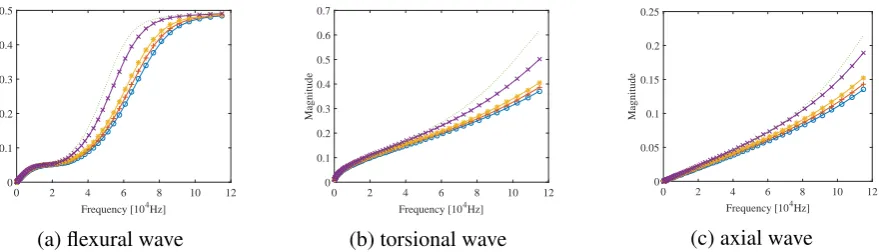
Numerical calculations are made up to 120 kHz with four propagating waves obtained over this frequency range. The waves are mainly flexural, torsional and axial waves.
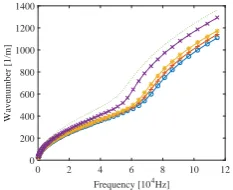
The effect of temperature on the wavenumber magnitude is exhibited in the torsional wave results over a temperature range of -100◦C to 150◦C (Fig. 7). Increase in wavenumber with respect to tem-perature is small over the range -100◦C to 90◦C compared to a high increase observe over temperature range beyond 90◦C.
Frequency [104Hz]
0 2 4 6 8 10 12
Wavenumber [1/m]
0 200 400 600 800 1000 1200 1400
Figure 7: Dispersion relations for torsional waves in the composite laminate at -100◦C(o), 25◦C(+), 90◦C(*), 110◦C (x) and 150◦C (· · ·)
[image:6.595.225.342.611.706.2]after the glass transition temperature varies significantly. Below the glass transition temperature, there exist slight increase in the reflection coefficients of all the wave types with a maximum difference of about 10% per 50◦C change in temperature. Above the glass transition temperature, a considerable difference is observed with respect to temperature change with an observed difference of about 28% per 50◦C change in temperature.
Frequency [104Hz]
0 2 4 6 8 10 12
Magnitude
0 0.1 0.2 0.3 0.4 0.5
(a) flexural wave
Frequency [104Hz]
0 2 4 6 8 10 12
Magnitude
0 0.1 0.2 0.3 0.4 0.5 0.6 0.7
(b) torsional wave
Frequency [104Hz]
0 2 4 6 8 10 12
Magnitude
0 0.05 0.1 0.15 0.2 0.25
[image:7.595.81.521.141.267.2](c) axial wave
Figure 8: Temperature dependent reflection coefficient magnitude of the composite laminate at -100◦C(o), 25◦C (+), 90◦C(*), 110◦C(x) and 150◦C(· · ·)
6.
Conclusion
The impact of temperature dependent mechanical characteristics of a layered sandwich structure on its wave interaction properties is exhibited in this article. The temperature dependent mechanical characteristics are separately measured for the facesheet and the core of the sandwich panel. The measured thermomechanical characteristics are used to calculate the temperature dependent wave interaction properties of the panel using a hybrid FE/WFE scheme. The scheme couples wave prop-agation properties within structural waveguides to inconsistency (such as damage) in the structure and is able to compute wave interaction coefficients for each propagating waves along the structure. Results exhibited a large divergence of the moduli and the material dissipation especially near and above the glass transition temperature of the panel resin. Similar behaviour is observed in the wave interaction results. It can be concluded that temperature is a significant factor that should be taken into consideration in the design process of aerospace structure.
REFERENCES
1. Rozenberg, L.B., Grishchak, L.E. and Ilman, V.M. Effect of temperature on the mechanical characteristics of carbon plastics reinforced with metal mesh,Polymer Mechanics,7, 320–322, (1973).
2. Barker, A.J. and Vangerko, H. Temperature dependent dynamic shear properties of cfrp,Composites,14, 141–144, (1983).
3. Maheri, M.R., Adams, R.D. and Galtonde, J.M. The effect of temperature on the dynamic characteristics of heat-resistant thermoplastic composites,Composites, Science and Technology,56, 1425–1434, (1996).
4. McNally, G.M., McCourt, M.P. and Spedding, P.L. The effect of rapid high temperature on the moisture absorption and dynamic mechanical properties of carbon fibre epoxy composite materials,Development in Chemical Engineering and Mineral Processing,12, 169–178, (2004).
5. Dimitrienko, Y.J. Thermomechanical behaviour of composite materials and structures under high temper-atures: 1. Materials, Composites,Applied Science and Manufacturing,28, 453–461, (1997).
7. Langley, R.S. A Note on the Force Boundary Conditions for Two-Dimensional Periodic Structures with Corner Freedoms,Journal of Sound and Vibration,167(2), 377–381, (1993).
8. Mace, B.R., Duhamel, D., Brennan, M.J. and Hinke, L. Finite element prediction of wave motion in structural waveguides,The Journal of the Acoustical Society of America,117(5), 2835–2843, (2005).
9. Chronopoulos, D., Troclet, B., Ichchou, M. and Laine, J.P. A unified approach for the broadband vibroa-coustic response of composite shells,Composites Part B: Engineering,43(4), 1837–1846, (2012).
10. Chronopoulos, D., Troclet, B., Bareille, O. and Ichchou, M. Modeling the response of composite panels by a dynamic stiffness approach,Composite Structures,96, 111–120, (2013).
11. Chronopoulos, D., Ichchou, M., Troclet, B. and Bareille, O. Efficient prediction of the response of layered shells by a dynamic stiffness approach,Composite Structures,97, 401–404, (2013).
12. Chronopoulos, D., Ichchou, M., Troclet, B. and Bareille, O. Predicting the broadband vibroacoustic re-sponse of systems subject to aeroacoustic loads by a Krylov subspace reduction, Applied Acoustics, 74
(12), 1394–1405, (2013).
13. D. Chronopoulos, M. Ichchou, B. Troclet, O. Bareille, Thermal effects on the sound transmission through aerospace composite structures, Aerospace Science and Technology, 30 (2013) 192–199.
14. D. Chronopoulos, M. Ichchou, B. Troclet, O. Bareille, Predicting the broadband response of a layered cone-cylinder-cone shell, Composite Structures, 107 (2014) 149–159.
15. D. Chronopoulos, M. Ichchou, B. Troclet, O. Bareille, Computing the broadband vibroacoustic response of arbitrarily thick layered panels by a wave finite element approach, Applied Acoustics, 77, 89–98, (2014).
16. Chronopoulos, D., Collet, M. and Ichchou, M. Damping enhancement of composite panels by inclusion of shunted piezoelectric patches: A wave-based modelling approach,Materials,8(2), 815–828, (2015).
17. Chronopoulos, D., Antoniadis, I., Collet, M. and Ichchou, M. Enhancement of wave damping within meta-materials having embedded negative stiffness inclusions,Wave Motion,58, 165–179, (2015).
18. Chronopoulos, D. and Antoniadis, I. and Ampatzidis, T. Enhanced acoustic insulation properties of com-posite metamaterials having embedded negative stiffness inclusions,Extreme Mechanics Letters, (2016).
19. Chronopoulos, D. Wave steering effects in anisotropic composite structures: Direct calculation of the energy skew angle through a finite element scheme,Ultrasonics,73, 43–48, (2017).
20. Ampatzidis, T. and Chronopoulos, D. Acoustic transmission properties of pressurised and pre-stressed composite structures,Composite Structures,152, 900–912, (2016).
21. Ben Souf, M.A. and Chronopoulos, D. and Ichchou, M. and Bareille, O. and Haddar, M. On the variability of the sound transmission loss of composite panels through a parametric probabilistic approach,Journal of Computational Acoustics,24, (2016).
22. Chronopoulos, D. Design optimization of composite structures operating in acoustic environments,Journal of Sound and Vibration,355, 322–344, (2015).
23. Polenta, V. and Garvey, S.D. and Chronopoulos, D. and Long, A.C. and Morvan, H.P. Optimal internal pressurisation of cylindrical shells for maximising their critical bending load,Thin-Walled Structures,87, 133–138, (2015).
24. Antoniadis, I. and Chronopoulos, D. and Spitas, V. and Koulocheris, D. Hyper-damping properties of a stiff and stable linear oscillator with a negative stiffness element, Journal of Sound and Vibration, 346, 37–52, (2015).