A New Hybrid Cycloconverter with Smooth Output Voltage Generation Capability
and Accurate Control of the Circulating Current
Christian Klumpner Tianning Xu Jon Clare
University of NottinghamSchool of Electrical and Electronic Engineering Nottingham NG7 2RD
UNITED KINGDOM
Abstract – Nowadays, power electronic converters based exclusively on IGBTs deliver excellent load side performance up to megawatt powers in the low voltage range (200-690V) and are steadily gaining performance in the medium voltage range as well. However, the medium and high voltage/high power range remains dominated by converters using naturally commutated thyristors (i.e. cycloconverters, current source inverters), which offer poorer output side performance. This paper proposes a new hybrid arrangement, targeting the medium and high-power range, comprising a naturally commutated cycloconverter connected to a PWM Voltage Source Inverter, able to offer improved output voltage quality and accurate control of the circulating current. The feasibility of the newly proposed concept is validated by Saber simulation results.
I. INTRODUCTION
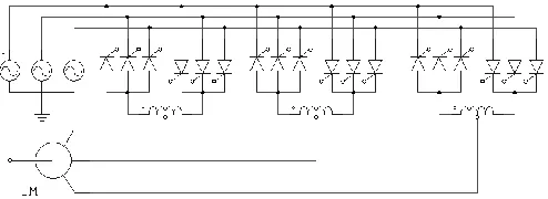
[image:1.612.51.298.610.700.2]A cycloconverter [1]-[9] normally comprises of a network of naturally commutated thyristors that bidirectionally connect each of the input lines to each of the output lines as Fig. 1 shows. In order to provide good synthesis of the output voltage waveform, it is very common to employ a multiphase supply with a small phase displacement between the voltage phasors, because the bidirectional switches are naturally commutated. This is normally achieved with phase-shifting transformers (delta-star or autotransformers). The disadvantage is that the assembly requires a huge number of devices and it is bulky as the transformers are designed for full power. Moreover, special attention should be paid to the design of the inter-phase reactors (IPR) that are used to limit the circulating current. Other disadvantages also exist: the output frequency is usually limited to 40 % of the input frequency and that the circuit has a poor input power factor due to the high content of harmonics and sub-harmonics in the input current. However, this solution is still used in the very high power range (>100 MW) drives, where there is no other type of semiconductor switch available.
Fig. 1. Topology of a standard 6-pulse cycloconverter.
This paper proposes a novel hybrid arrangement that can solve the main problems with the standard cycloconverter topology by connecting a lower voltage rated H-bridge inverter in each of the output phases of the cycloconverter and controlling it in a way similar to a series connected active filter to improve the shape of the output voltage [10]. Additionally it will be shown that the circulating current can be controlled with good accuracy while employing a smaller inductor size, and that accurate control of the circulating current improves the quality of the input currents.
II. THE HYBRID CYCLOCONVERTER
A. Operation of a Standard Cycloconverter
A cycloconverter is a direct frequency converter consisting of three 3-phase bi-directional thyristor bridges [1-3]. There are many topologies in use depending on the number of pulses of the thyristor bridges (6-12-18-24 etc) and if their operation relies on circulating current or not. The output voltage of a 6-pulse thyristor bridge is controlled by adjusting the firing angle ():
maxcos
out
V
V
V
max
3 3
E
(1)If the firing angle is kept constant, the output is DC; whereas if the angle is modulated according to (2), it will generate an AC output voltage of adjustable frequency and amplitude:
1
max
cos
V
out pkV
sin 2
f
outt
(2)Even though the operation is straightforward, there are some disadvantages, particularly a high content of harmonics in the output voltage, dependent on the number of pulses. The higher the number of pulses, the better the waveform, but this is at the expense of increased complexity. Also poor control over the circulating current causes additional distortion of the load current and poor power quality on the input side. All existing solutions to mitigate these problems are exclusively based on passive components (phase shift transformers and inter-phase reactors) and as a result they are bulky, as the size of magnetics is dependent on the frequency of the ripple (number of pulses times the input frequency).
B. The Principle of the Hybrid Approach
series active filter. It will cancel the low frequency ripple in the output voltage and facilitate accurate control over the circulating current by switching faster whilst being rated at only a fraction of the supply voltage.
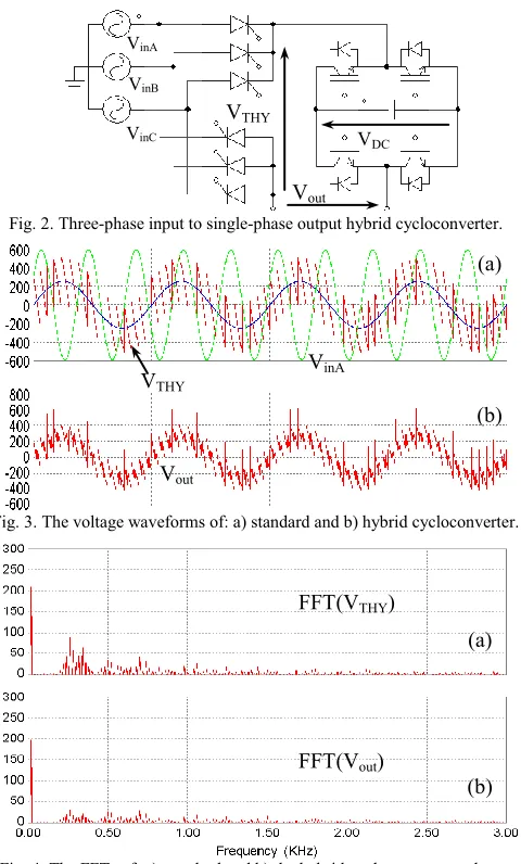
Fig. 2 shows a 3-phase thyristor rectifier operating as a cycloconverter (using (2) as a reference the firing angle) with an additional H-bridge inserted in series with the positive output line. In Fig. 3a, the waveforms of the input phase voltage, the reference voltage and the thyristor bridge output voltage (VTHY) are presented. The H-bridge inverter uses as a
reference the difference between the reference voltage of the cycloconverter and the voltage that the cycloconverter is actually producing VTHY, which has a high 300 Hz harmonic
content (Fig. 4a), typical for the operation of a 6-pulse thyristor bridge. As the H-bridge switches five times faster than the thyristor bridge, it is able to compensate the 300 Hz ripple, as shown in Fig. 3b (waveform) and Fig. 4b (its spectrum).
Fig. 2. Three-phase input to single-phase output hybrid cycloconverter.
[image:2.612.56.296.265.663.2]Fig. 3. The voltage waveforms of: a) standard and b) hybrid cycloconverter.
Fig. 4. The FFTs of: a) standard and b) the hybrid cycloconverter voltage.
The voltage waveform is clearly improved from a THD of approx. 81 % down to 47 % with most of the harmonics appearing now at higher frequency, which will be filtered now much more effectively by an inductive type of load. More advanced control that can actually calculate the real
average voltage that needs to be compensated would provide much better performance. The feasibility of the idea can be better evaluated by looking at the reduction of the highest in magnitude-low order frequency harmonics (260 and 340 Hz) from about 85 V to 30 V, which means almost by a factor of four. Also the 60 V side bands (240 Hz, 280 Hz, 320 Hz and 360 Hz) are reduced to approx 25 V.
However, having identified the potential benefits, it is necessary to implement the hybrid concept into a realistic simulation model that considers realistic thyristor models and takes into account the necessity of having circulating current in the cycloconverter stage.
III. THE EVALUATION OF A STANDARD CYCLO-CONVERTER WITH CIRCULATING CURRENT
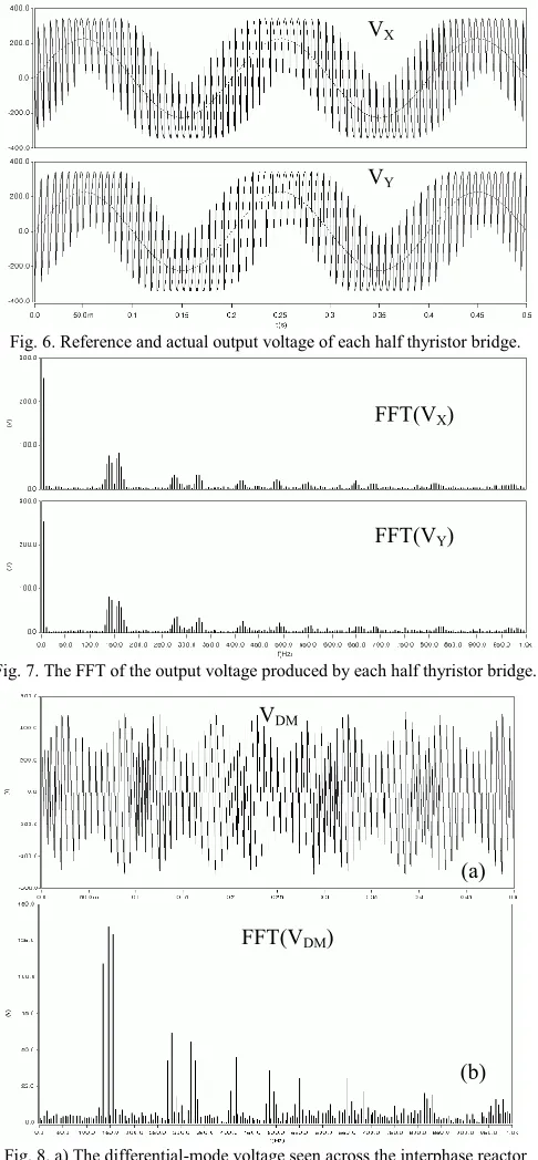
Fig. 5 shows the basic diagram of a 3-phase to 1-phase standard cycloconverter with an inter-phase reactor (IPR) connected on the output side to limit the circulating current. Fig. 6 shows the typical waveforms of the voltages at the output of each half of the thyristor bridge VX and VY, each
containing the same fundamental voltage but having different profile for the 150 Hz voltage ripple caused by the commutation of the thyristors. As the two outputs are connected together via the interphase reactor, the fundamental voltage appears as a common mode voltage and therefore is not attenuated by the interphase reactor. The 150Hz components for example are in anti-phase and their sum appears as a differential component across the interphase reactor, producing the circulating current shown in Fig. 9. The spectrum of this differential voltage (Fig. 8b) reveals important harmonic components, the highest (approx 135 Vpeak) around 150 Hz and smaller ones around 300 Hz
[image:2.612.329.545.456.560.2]and 450 Hz.
Fig. 5. Schematic of 3-ph to 1-ph cycloconverter with interphase reactor.
The circulating current therefore can be limited by designing the value on the inter-phase reactor accordingly. For example in the particular case simulated here, in order to limit the 150 Hz circulating current harmonic to 8 Apk caused
by the 135 Vpk voltage harmonic, a total value of the
inter-phase inductance of 17.9 mH would be necessary.
The circulating current and its FFT are shown in Fig. 9 for the situation when the interphase reactor consists of two 10 mH coupled inductances with a coupling coefficient of 0.9 that gives 18mH mutual inductance, which is very close to the numerical example previously mentioned. The FFT of the circulating current reveals a current component at 150 Hz of approx 7.5 Apeak, similar to what was predicted.
VinC
VTHY VinB
VinA
VDC
Vout
FFT(VTHY)
FFT(Vout)
(a)
(b) VTHY
Vout
VinA
(a)
(b)
VC
VCYCLO VB
VA
VX VY
IPR
Fig. 6. Reference and actual output voltage of each half thyristor bridge.
Fig. 7. The FFT of the output voltage produced by each half thyristor bridge.
Fig. 8. a) The differential-mode voltage seen across the interphase reactor and b) its FFT.
As the load is connected to the centre tap of the inter-phase reactor and as some of the switching voltage ripple is 180 degrees displaced, it will cancel completely at the centre tap as shown in Fig. 10a where its potential is shown. In Fig. 10b that shows its spectrum, it is clear that only two important voltage harmonics around 150 Hz are present instead of the four shown in Fig. 7. Another aspect that would lead to even better harmonic reduction is that most of the loads have a floating neutral, which means that the line-to-line voltage waveform shown in Fig. 11 would be relevant for evaluating the load side performance of the cycloconverter.
Fig. 9. a) The circulating current and b) its FFT.
Fig. 10. a) The cycloconverter ph-to-supply neutral output voltage; b) FFT.
Fig. 11. a) The cycloconverter line-to-line output voltage and b) its FFT.
VDM
FFT(VDM)
(a)
(b)
zoomed
(a)
(b) FFT(Vout-LL)
Vout-LL zoomed
VCYCLO
FFT(VCYCLO) (b)
(a) (a)
(b) FFT(Icir)
Icir
VX
VY
FFT(VX)
[image:3.612.54.297.56.580.2]The downside of limiting the circulating current using an interphase reactor is the presence of a large DC component of 19.3 A, and some very low frequency current ripple of 10 Hz, which is double the output frequency. These cannot be limited by an interphase reactor and would cause additional distortion of the input current, large reactive power and therefore a poor input current power factor. Another aspect is that large DC and low frequency components in the circulating current would also cause saturation of the IPR, which can be avoided only by increasing its size.
IV. THE CONTROL OF HYBRID CYCLOCONVERTERS
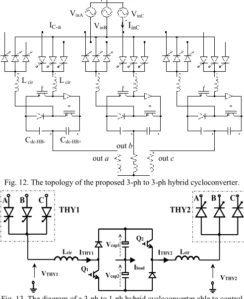
[image:4.612.51.297.375.677.2]The ideal model of the hybrid converter presented in the beginning of this section did not accounted for the presence of circulating current, which was identified as a serious problem in the previous subsection. In order to minimize the size of the interphase reactor, an additional feature should be added to the H-bridge inverter: the cancellation of the low frequency common mode voltage components between the outputs of the two thyristor bridge halves. In order to do that, a modified hybrid topology, shown in Fig. 12 and 13, should be employed, consisting of six IGBTs/diodes embedded in three asymmetrical H-bridge inverters with split DC-link capacitors. The asymmetrical inverter leg structure is a perfect fit to each thyristor half bridge because both are designed to handle unidirectional (positive/negative) current.
Fig. 12. The topology of the proposed 3-ph to 3-ph hybrid cycloconverter.
Fig. 13. The diagram of a 3-ph to 1-ph hybrid cycloconverter able to control the circulating current.
In this model (Fig. 13), each H-bridge inverter leg would operate with an independent duty-cycle, that would result from taking into account two control objectives:
In order to cancel the 150/300/450 Hz voltage ripple, each H-bridge leg should inject a voltage that is opposite to what the thyristor half bridge inherently injects, in order to provide a ripple free voltage at the middle point of the split dc-link.
In order to control the circulating current, a PI controller should be employed that will produce a voltage output that will be added/subtracted from each H-bridge inverter leg reference voltage
The structure of the control system is presented in Fig. 14. A fast PI controller is used in order to accurately control the circulating current, which in this approach is measured but an important issue in future research will be the removal of this current transducer. The output of this controller (which estimates the amount of voltage drop that will appear across the two inductances (Lcir) in order to make the circulating
current follow its reference) is added to the differential mode voltage produced by the two thyristor half bridges. The common mode voltage produced by the two thyristor half bridges, which in a normal cycloconverter will be its output voltage, is subtracted from the reference ripple-free waveform, producing the common-mode voltage that needs to be injected by the H-bridge inverter VCM in order to
remove all the unwanted low frequency voltage distortions. These two components are used to produce the voltage reference for each leg of the H-bridge inverter VHB1 and
VHB2.
Fig. 14. Control diagram of the hybrid cycloconverter.
In order to ensure proper operation of the H-bridge inverter, the capacitor voltages Vcap1 inverter Vcap2 are monitored by a
slow PI controller, that generates a smooth offset signal that is added/subtracted from the reference voltage that produces the firing angles for the two thyristor half bridges THY1 and THY2. The duty-cycles of the two transistors Q1 and Q2 are determined by dividing the reference voltage of each H-bridge inverter leg to the capacitor voltage. The gate pulses are produced by the PWM generator block by multiplying the two duty-cycles with the switching period and arranging the switching states of the H-bridge accordingly. The active switching state will generate the desired common mode voltage reference VCM, whilst the ratio between the two zero
switching states (Q1&Q2=ON or Q1&Q2=OFF which means
that the H-bridge inserts Vcap1 and Vcap2 with opposite
polarities in the circuit, ideally cancelling each other) generates the desired differential mode reference VDM.
Icir_ref
Icir
PI ctrl PI ctrl
VTHY1 VTHY2 PWM 1/2 Vcap1 Vcap2 1/2 Vcap Q1 Q2 Vcap_ref PI ctrl PI ctrl VDM VCM OffsetTHY clock S&H S&H VHB1_ref
VHB2_ref dQ2 dQ1 timer Vout_ref K1 THY1 K2 VTHY1_ref VTHY2_ref THY2 VinC VinB VinA
Cdc-HB- Cdc-HB+
L cir L cir
out a out c
out b
IC-a IinC
THY1 THY2 VTHY1 VTHY2 Vcap1 Vcap2 Q1 Q2
ITHY1 ITHY2
Iload
A B C A B C
Lcir
[image:4.612.318.560.379.514.2]V. THE EVALUATION OF THE HYBRID CYCLOCONVERTER
A simulation model of the hybrid cycloconverter has been implemented in SABER with the circuit parameters mentioned in the Appendix A.
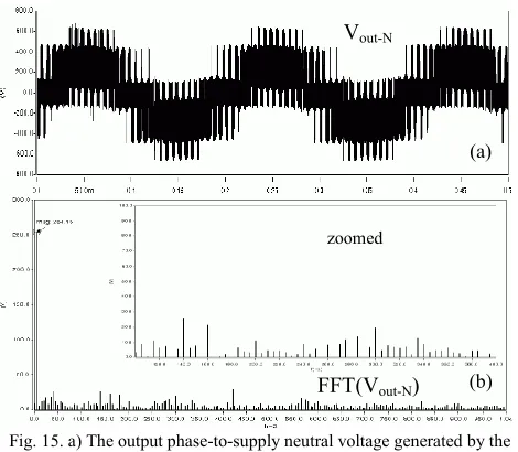
Fig. 15 shows the line-to-line output voltage waveform and its FFT. The high level (80V=30%) low-order harmonics noticed in the FFT of the output voltage of the standard cycloconverter (Fig. 4) are effectively reduced to less than 30V (<12%) due to the operation of the H-bridge inverters. This can also be seen in Fig. 16, where the load currents and the FFT are shown to be nearly sinusoidal. The capability to accurately control the circulating current is proven in Fig. 17 where the circulating current and its FFT is shown to vary around the 2 A reference with only 1A ripple, which minimises the amount of stored energy in the two inductances and therefore the size because maintaining the circulating current under control by means of forced switching will not only reduce the value of the inductance but also the peak current it should handle.
Fig. 15. a) The output phase-to-supply neutral voltage generated by the hybrid cycloconverter and b) its FFT.
Fig. 18a shows the zero-sequence component present in all the three H-bridge inverter references. These components do not give rise to current in a three-phase load that has no connection to the supply neutral (3-wire fed). The importance of detecting this component may offer the possibility to reduce the amount of voltage that each H-bridge needs to synthesise, with the impact on reducing the voltage rating of these components. Fig. 18b shows the variation of the two H-bridge capacitor voltages around the 280 V reference, with twice the output frequency. This reveals also one of the disadvantage of this topology: the fact that there is AC-current flowing through the capacitors. One solution would be to add an additional inverter leg to the bridge, that will require only one DC-link capacitor and would reduce the voltage ratings to a half.
Fig. 19 reveals the two components in the H-bridge reference voltage: the differential mode reference voltage
that controls the circulating current and the common mode reference that aims to remove the low order distortion.
Fig. 16. a) The hybrid cycloconverter load currents and b) its FFT.
Fig. 17. a) The circulating current in the hybrid cycloconverter; b) its FFT.
[image:5.612.314.563.76.727.2]Fig. 18. a) Zero-sequence component in all three H-bridge inverters reference output voltage; b) the H-bridge capacitor voltages.
Fig. 19. The two components of the H-bridge reference: a) the differential mode reference voltage and b) the common mode reference voltage.
(b) (a)
(b) (a)
Iout-a Iout-b Iout-c
FFT(Iout-a)
(b) (a)
Icirc
FFT(Icirc)
(b) (a)
zoomed
Vout-N
(b) (a)
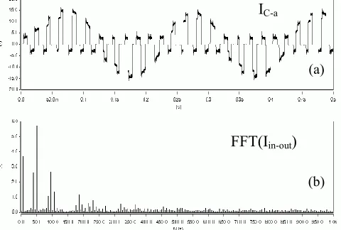
[image:5.612.56.291.306.511.2]Fig. 20 shows the input current that contributes to the generation of a given output current and its FFT, being modulated with the output frequency. Fig. 21 shows the cumulative input phase current that contributes to the generation of all three-load currents and its FFT. It is clear that most of the sub-and inter-harmonics caused by the output frequency pulsation disappear due to harmonic cancellation. However, a few inter harmonics remain: 3Apk(17%)@85Hz, 3.7Apk(21%)@185Hz, 2Apk(11%)@215
Hz, 1.8Apk(10%)@320Hz, but the performance is far better
than of a standard 6-pulse cycloconverter.
Fig. 22 shows the instantaneous power delivered to the load and the one absorbed from the input side. Both have the same average (2.75 kW), but the output power is smooth revealing little harmonics in the load currents whilst the input power has a high degree of ripple, revealing a more distorted supply current and also the fact that this power ripple is smoothed by the three H-bridge inverters.
Fig. 20. a) The hybrid cycloconverter input ph. current (3ph/1ph) and b) FFT
Fig. 21. a) The hybrid cycloconverter input current (3ph/3ph) and b) its FFT.
Fig. 22. a) The hybrid cycloconverter output power and b) input power.
VI. CONCLUSIONS
In this paper, a new hybrid cycloconverter topology is proposed, which consists of a 6-pulse cycloconverter and three asymmetric H-bridge inverters operated as series active filters. This hybrid topology provides not only harmonic-free spectrum in the low frequency range where standard 6-pulse cycloconverters behaves badly, with direct impact on removing the phase shift transformers/autotransformers and reducing the number of thyristors needed, but also an accurate control of the circulating current which allows for further minimisation of the interphase/output inductances and improved power quality of the input currents. Future work will investigate the possibility to use coupled inductances to reduce the voltage ratings of the H-bridge inverters.
VII. ACKNOWLEDGMENT
Support for this work from the EPSRC is gratefully acknowledged (Grant EP/C52652X/1).
VII. APPENDIX A.
Simulation parameters common for all simulation results: Vin-line= 415 VRMS, fin= 50 Hz,fout= 5 Hz, Lload= 0.5 H, Rload
= 15 ; standard cycloconverter (Fig. 6-11): LIPR = 2x10mH
(coupled kIPR= 0.9), RIPR= 0.05; hybrid cycloconverter (Fig.
12-22): fsw-HB= 5kHz, Lcirc= 2x10mH (no coupling), Rcirc=
0.05, Vcap-ref= 2x280V, Cdc-HB=2x10mF (series).
IX. REFERENCES
[1] B.R. Pelly, “Thyristor phase-controlled converters and cycloconverters”, Wiley Interscience, 1971.
[2] W. McMurray, “The Theory and Design of Cycloconverters” Massachusetts Inst. of Tech. Press, Cambridge, MA, 1972. [3] R. Hagmann, “AC-cycloconverter drives for cold and hot
rolling mill applications”, IEEE Proc. of IAS’91, Vol.2, pp. 1134-1140, 1991
[4] Y. Tamura, S. Tanaka, S. Tadakuma, “Control method and upper limit of output frequency in circulating-current type cycloconverter”, IEEE Int. Semicond. Power Converter Conf., 1982, pp, 313-323.
[5] J. Trautner and A. Wick, “DC Link converter and cyclo-converter-fed AC motors: The concepts and properties of large variablespeed drives,” Siemens Rev.(Energy&Automation -Issue on Large Electric Motor&VSD), vol. 1, pp. 16–31, 1988. [6] H. Akagi, “Large static converters for industry and utility applications,” Proc. IEEE, Vol. 89, No. 6, pp. 976–983, 2001. [7] Y. Liu, G.T. Heydt, R.F. Chu, “The Power Quality Impact of
Cycloconverter Control Strategies”, IEEE Trans. on Power Delivery, Vol.20, No.2, pp.1711-1718, 2005.
[8] P. Syam, P.K. Nandi, A.K. Chattopadhyay, “Effect of output current ripple on the input supply current and the power quality for a cycloconverter-fed drive”, Proc. IEE Part-B, EPA, Vol.151, No. 04, pp.425-433, July 2004.
[9] J.R. Rodriguez, J.Pontt, P. Newman, R. Musalem, H. Miranda, L.Moran, “Technical Evaluation and Practical Experience of High-power Grinding Mill Drives in Mining Applications”, IEEE Trans. on Ind. App., Vol. 41, No. 3, pp. 866-874, 2005. [10] C. Klumpner, T. Wijekoon, P. Wheeler, “A New Hybrid
AC/AC Power Converter”, IEEE Proc of IAS’05, Vol. 4, pp. 2374-2381, 2005.
FFT(I
in-out)
I
C-a(a)
(b)
I
inCFFT(I
inC)
(a)(b)
2 2 2
L out a out b out c
[image:6.612.54.294.269.431.2] [image:6.612.53.301.360.710.2]