Research Article
End-To-End Mobility for the Internet Using ILNP
Ditchaphong Phoomikiattisak
1and Saleem N. Bhatti
2 1Geo-Informatics and Space Technology Development Agency, Bangkok, Thailand 2School of Computer Science, University of St Andrews, St Andrews, Fife KY16 9SX, UKCorrespondence should be addressed to Saleem N. Bhatti; [email protected]
Received 7 May 2018; Revised 13 December 2018; Accepted 20 January 2019; Published 16 April 2019
Academic Editor: Yu Chen
Copyright © 2019 Ditchaphong Phoomikiattisak and Saleem N. Bhatti. This is an open access article distributed under the Creative Commons Attribution License, which permits unrestricted use, distribution, and reproduction in any medium, provided the original work is properly cited.
As the use of mobile devices and methods of wireless connectivity continue to increase, seamless mobility becomes more desirable and important. The current IETF Mobile IP standard relies on additional network entities for mobility management, can have poor performance, and has seen little deployment in real networks. We present a host-based mobility solution with a true
end-to-end architecture using theIdentifier-Locator Network Protocol (ILNP). We show how the TCP code in the Linux kernel can be
extended allowing legacy TCP applications that use the standard C sockets API to operate over ILNP without requiring changes or recompilation. Our direct testbed performance comparison shows that ILNP provides better host mobility support than Mobile IPv6 in terms of session continuity, packet loss, and handoff delay for TCP.
1. Introduction
Mobility is an increasingly important aspect of communi-cation for the Internet. The usage of handheld computing devices, such as tablets and smartphones, is increasingly popular among Internet users. However, the current Internet Protocol, IP, was not originally designed to support mobility for mobile nodes (MNs) over the Internet. While the IETF
Mobile IPv4 (MIPv4)[1] andMobile IPv6 (MIPv6)[2]
solu-tions have been defined for some time and implementation is available, they have seen little deployment due to their complexity and performance.
In this paper, we describe and evaluate an implementation of a true end-to-end approach to mobility. Our mechanism uses ILNPv6, a superset of IPv6 that implements an
Inter-net architecture described by theIdentifier-Locator Network
Protocol (ILNP). We present a testbed-based performance
evaluation of ILNPv6 as an in-kernel modification to the Linux kernel (not a simulation). Using an unmodified TCP application, we show that our approach is fully backwards compatible with the existing sockets API and has better performance than MIPv6.
1.1. Contributions of This Paper. Our overall exposition in
this paper is placed in the context of the first comprehensive
performance evaluation of a Linux kernel implementation of TCP running over ILNPv6 in direct comparison with TCP over Mobile IPv6 (MIPv6). In so doing, we make the following scientific and engineering contributions:
(i) We present an architectural evaluation of an Identifier-Locator based solution to mobility (ILNP) against the current IETF architectural approach. We show that a new Internet architecture, which has a radically different approach to addressing, can be used over current infrastructure to implement IP-level
mobility.This includes detailed, qualitative
protocol-level analysis against MIPv6 as well as comparisons with the other IETF proposals.
(ii) To evaluate our new architectural approach, we pro-vide a rigorous empirical performance comparison of TCP operation over ILNPv6 against MIPv6, both with and without MIPv6 Route Optimisation (RO)
enabled.We show that ILNPv6 outperforms MIPv6 in
all cases we have tested. We provide the first detailed analysis of flow-level handoff dynamics for MIPv6,
in comparison with ILNP. Our evaluation includes
operation over different end-to-end delays and exam-ination of throughput, delay, loss, and retransmission attempts during the handoff period.
(iii) To assess application-level impact, we have compared in detail the performance of TCP CUBIC (the Linux default TCP variant) with TCP Hybla [3] and TCP Veno [4], the latter two TCP variants having designs that are optimised for wireless and heterogeneous
networks. Crucially, we show that the use of ILNP
changes the design landscape for transport protocol
operation in mobile IP scenarios. Current transport
protocols assume the presence of loss during handoff, and so their designs are focused on dealing with
loss. ILNP drastically reduces gratuitous loss during
handoff (to near zero loss), so loss is no longer a major factor to consider in the transport protocol design for handoff. Immediately, this has benefits in performance for all existing TCP variants, as loss causes TCP to slow down transmission through its normal congestion control behaviour.
(iv)We have shown that it is possible for an architecturally
radical approach, such as ILNP, which deprecates the use of IP addresses, to be implemented directly on current systems and work across current IPv6
infrastructure. We extended our codebase from [5]
allowing existing (legacy) IPv6 TCP applications to operate over ILNPv6 without modification, as ini-tially demonstrated with some basic results in [6]. Our results in this paper are based on an in-kernel implementation and are fully backwards compatible
with the existing C sockets(2)API. This
demon-strates a realistic and tractable path to enable both backwards compatibility and incremental deployment for ILNP.
Overall, we show that it is possible to deploy on today’s IPv6 infrastructure a new and truly end-to-end mobility architecture for IP. This new architecture does not require any of the additional mechanisms that are used in other IP mobility solutions: tunnelling; agents; proxies or other middleboxes; overloading of IP address semantics; or any additional entities, protocols, or state for routing.
1.2. Structure of This Paper. We start with an overview of
ILNP and with a description of the handoff process for ILNP and mobile IP in Section 2. Then, the most relevant related work is presented in Section 3, with the focus on solutions that have been assessed by the IETF or IRTF for potential global deployment. In Section 4, we describe the ILNPv6 extensions to TCP, showing how ILNPv6 can be implemented as a superset of IPv6. Section 5 provides a description of the testbed and metrics used for our evaluation. Thorough comparative performance evaluation of TCP over ILNPv6 and MIPv6 on our testbed is presented in Section 6. After a discussion of some key issues in Section 7, we conclude with a summary in Section 8.
1.3. Abbreviations and Acronyms
API: Application Programming Interface;
AR: Access Router;
BU: Binding Update; CN: Correspondent Node;
CoA: Care-of Address; EID: Endpoint Identifier;
FA: foreign agent;
FMIP: Fast Handover for Mobile IP;
FQDN: Fully Qualified Domain Name;
HA: home agent; HI: Host Identifier;
HIP: Host Identity Protocol; HMIP: Hierarchical Mobile IP;
HoA: home address;
IETF: Internet Engineering Task Force;
IRTF: Internet Research Task Force; ILNP: Identifier-Locator Network Protocol;
ILNPv6: ILNP as a superset of IPv6; L64: 64-bit locator value for ILNP;
LAN: Local Area Network;
LISP: Locator-Identifier Separation Protocol; LMA: Local Mobility Anchor;
LU: Locator Update;
MAG: Mobile Access Gateway;
MIP: Mobile IP; MN: Mobile Node;
MP-TCP: Multipath Transmission Control Protocol;
MSS: Maximum Segment Size; NAT: Network Address Translation; NCoA: Next Care-of Address
NID: 64-bit node identifier for ILNP;
OTA: Over the Air; PMIP: Proxy Mobile IP;
PoA: Previous Care-of Address; RA: Router Advertisement;
RLOC: Routing Locator; RO: routing optimisation;
RTT: round trip time;
RVS: Rendezvous Server;
SCTP: Stream Control Transport Protocol;
SHIM6: Level 3 Multihoming Shim Protocol for IPv6; TCP: Transmission Control Protocol;
UDP: User Datagram Protocol; WAN: wide-area network;
Table 1: Use of names in IP and ILNP (modified from [7].).
Protocol layer IPv4 and IPv6 ILNP (ILNPv6)
Application FQDN, IP address FQDN or app.-specific
Transport IP address Node Identifier (NID)
Network IP address Locator (L64)
(interface) IP address dynamic binding
∗FQDN: fully qualified domain name.
/∗ IPv6 − RFC4291 + RFC3587 ∗/
64 bits
64 bits 64 bits
64 bits
IPv6 Unicast Routing Prefix
/∗ ILNPv6 − RFC6741 ∗/
Interface Identifier
Locator (L64) Node Identifier (NID)
Figure 1: IPv6 unicast address format and ILNPv6 unicast address format. The L64 value has the same syntax and semantics as the IPv6 routing prefix. The NID value has the same syntax as the IPv6 Interface Identifier but has different semantics.
2. ILNP: A New Architecture
Supporting Mobility
TheIdentifier-Locator Network Protocol (ILNP)[7–17] is an
Internet Research Task Force (IRTF) Experimental protocol. It has a host-based, end-to-end architecture, is designed to support mobility (in harmony with other functions, such as multihoming), and can be implemented as a superset of IPv6
calledILNPv6.
2.1. Identifier-Locator Approaches to Networking. While the
first ideas on separation of identity and location were dis-cussed at the very early stages of thinking for the Internet [18], these ideas were not incorporated into the architectural design. Since then, the potential problems in the way IP addresses are used have been highlighted by the Internet community at intervals over several decades, e.g., in 2007 [19], in 1997 [20], and in 1977 [18]. Indeed, it is necessary to reconsider the use of addressing and the (mis)use of IP addresses in general [21].
So, the use of an Identifier-Locator approach to network-ing is now receivnetwork-ing considerable interest in the research community. There are many engineering solutions proposed, not just for mobility (e.g., [22, 23]), but also for improving routing scalability (e.g., [24–26]).
2.2. Architecture: Overview. A key architectural concept of
ILNP [7] is the recognition that the overloaded use of IP addresses and static bindings between objects in the com-munication stack creates major problems in implementing functions (such as mobility) for the Internet [21].
So, ILNP deprecates the use of IP addresses, replac-ing them with two new distinct data types to explicitly
acknowledge the presence of anidentityand a locationfor
an IP node. ILNPv6 defines bothnode identifier (NID)and
networklocator (L64)values, along with dynamic bindings
to implement various functionalities, including host mobility. As shown in Table 1, instead of using the IP address in various layers across the protocol stack, ILNPv6 uses NID and L64 values. Transport-layer protocols bind only to a NID value, an identifier for a (logical, virtual, or physical) node that has no topological semantics. This is to maintain end-to-end state invariance for transport protocol session state. The NID represents an identity of a node which is tied to the whole node, not just a single network interface for that node. The network layer uses a L64 value, which is topologically significant, for routing and forwarding. The L64 value represents a single IPv6 subnetwork.
In addition, there are one-to-many dynamic bindings between NID and L64 values, as well as another set of dynamic bindings between physical interfaces and L64 val-ues. Hence, mobility in ILNP is implemented by adjusting these dynamic bindings between NID and L64 values and between L64 values and interfaces. The L64 values can change as a mobile node (MN) moves without impacting end-to-end state invariance, as the NID value always remains stable. MNs can have multiple NID and L64 values and use multiple interfaces simultaneously, by adjusting dynamic bindings between them as required.
cell 1
cell 2 MN
MN
MN
(1){IM, L1}
(2){IM, L1| L2}
(3){IM, L2}
AR1
AR2
Internet
{IC, LC}
AR = access router CN = correspondent node
CN
MN = mobile node
[image:4.600.171.430.73.217.2]= packet flow = movement of MN
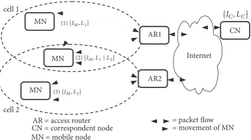
Figure 2: An example scenario of host mobility with ILNP using network layer (IP layer) soft-handoff. A mobile node (MN) at(1)uses
identifier𝐼𝑀and locator𝐿1at access router AR1. As the MN moves from cell 1 to cell 2, in the overlap region(2), it can use both its current
locator,𝐿1, and a new locator value,𝐿2, that is provided by AR2 in cell 2. (The new locator value is identical to an IPv6 routing prefix, as
can be discovered from IPv6 Router Advertisement (RA) messages.) In the overlap region, MN is multihomed. When MN moves into cell
2 completely(3), it uses only𝐿2. As𝐼𝑀does not change, end-to-end state invariance can be preserved for transport protocols, maintaining
end-to-end integrity.
it is only those end-systemsthat need to use IPv6 that are
upgraded; thesitenetwork devices (switches and routers) do
not necessarily need to be upgraded, as long as they support IPv6 already.
2.3. A Simple Mobility Scenario. Figure 2 shows a simple
example of handoff in ILNPv6. A MN, with NID value
𝐼𝑀, using locator 𝐿1 in cell 1 moves to cell 2, where it
will use locator 𝐿2. When the MN enters the overlapping
region between cell 1 and cell 2, the value of 𝐿2 would be
available to MN through IPv6 Router Advertisements (RAs); it is simply the IPv6 address prefix required for cell 2. The
MN receives 𝐿2 and now informs the correspondent node
(CN) of this new value using aLocator Update (LU)message
[12], synonymous to an IPv6 Binding Update (BU) message.
TheLocator Update Acknowledgement (LU-ACK)is sent back
from the CN once the LU is processed. If required, the MN also securely updates its relevant DNS entries (e.g., the L64 record) to allow incoming sessions to be correctly established. The use of DNS for ILNP is described in [11, 27], but is only required for nodes that expect incoming connections, e.g., mobile servers. At this point, the MN could just drop the use
of𝐿1 (when usinghard-handoff) or permit a NID value to
be bound to both L64 values (when usingsoft-handoff). For
hard-handoff, gratuitous packet loss could occur for the in-flight packets sent from the CN using the stale L64 value. In contrast, packet loss during soft-handoff is minimised. This is because the MN maintains bindings with both L64 values
(𝐿1and𝐿2) when it stays in the overlap region between the
two networks; i.e., it is multihomed during handoff. This is advantageous when there is no soft-handoff supported by the subnetwork technology across the handoff region, e.g., between different administrative WLAN cells or between different technologies such as from a 3G or 4G cell to a WLAN cell in a vertical handoff scenario.
2.4. Handoff Process for MIP and ILNP. For our evaluation in
Section 6, we compare directly MIPv6 with ILNPv6 in terms
of their performance for application flows during handoff. So, in this section, we describe the differences in the handoff process between MIPv6 and ILNPv6.
In summary, the ILNPv6 handoff process has approxi-mately the same overhead as that for MIPv6 without route optimisation (RO). However, MIPv6 without RO causes performance problems for the data flow during handoff, due
to the well-known problem oftriangular routingfor MIP. So,
it is recommended that MIPv6 is always used with RO. Our experiments in Section 6 consider MIPv6 with and without RO, for a rigorous evaluation. (Our results here are all for TCP, but a comparison of the handoff process with UDP data flows is presented in our previous work [5].)
2.4.1. MIPv6 Handoff. When a MN performs handoff in
MIPv6, the new care-of address (CoA) of the MN must be updated at its home agent (HA). If RO is in use, the CN must also be made aware of the new CoA, so that data packets can be delivered to the correct location in the network. Figure 3 shows the signalling required for handoff for MIPv6 without RO. Two signals are required: (i) a Binding Update (BU) from the MN to the HA and (ii) a Binding Acknowledgement (BAck) in response, to inform the MN that the BU has been
processed. In Figure 3,𝑇𝐻𝐴denotes the processing time at the
HA.
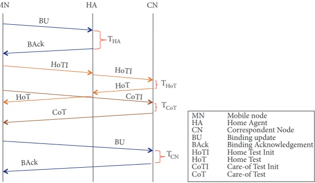
If RO is enabled, additional signals are required as shown in Figure 4:
(i)Home Test Init (HoTI) and Home Test (HoT) are
needed to test the reachability of the HoA from the
CN. (𝑇𝐻𝑜𝑇is the time taken to process the HoT at the
CN.) Both HoTI and HoT must be sent via the HA.
(ii)Care-of Test Init (CoTI)and Care-of Test (CoT) are
needed to test the reachability of the new CoA from
the CN. (𝑇𝐶𝑜𝑇is the processing time of CoT at the
MN HA
BU
BAck
THA
MN Mobile node
HA Home Agent
BU Binding update
[image:5.600.148.451.77.178.2]BAck Binding Acknowledgement
Figure 3: The handoff process for MIPv6 without RO.
MN HA CN
BU
BAck
BU
BAck HoT
HoT
CoTI
CoT
HoTI
HoTI
THA
THoT
TCN
TCoT
MN Mobile node
HA Home Agent
CN Correspondent Node
BU Binding update
BAck Binding Acknowledgement
HoTI Home Test Init
HoT Home Test
CoTI Care-of Test Init
CoT Care-of Test
Figure 4: The handoff process for MIPv6 with RO.
(iii) BU and BAck between the MN and the CN to update
the CoA. (𝑇𝐶𝑁is the time taken to process the BU at
the CN.)
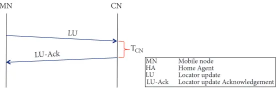
2.4.2. ILNPv6 Handoff. The handoff process in ILNPv6 is
much simpler: all that is required is that the newL64value of
the MN is signalled to the CN. As shown in Figure 5, ILNPv6 uses a simple handshake: LU and LU-ACK, directly between
the MN and the CN. (𝑇𝐶𝑁is the time taken to process the LU
at the CN.)
In some situations, the MN may also need to update the L64 value to a directory service, such as the DNS. However, this would only be required if the MN is a mobile server and expects incoming connections, e.g., if a WWW server is running. Even then, this may depend on the application: many applications have their own mech-anisms for establishing presence—an application-specific
rendezvousservice—and do not rely on DNS. For example,
Skype uses a peer-to-peer model with its own presence and resolver mechanism [28]. If specific application-level integration was required for ILNP, further studies would be needed. So, this process is not included in our stud-ies because it is not always necessary for an MN but is suitable for future work in an application-specific con-text.
3. Related Work
We present here a selection of proposed solutions for host mobility support, focusing on those that have been reviewed by the IETF or the IRTF, i.e., those that are considered to be deployable at scale. A more comprehensive list of mobility solutions can be found in RFC6301 [29] and also previous surveys of mobility mechanisms [30, 31].
Table 2 compares these selected mobility solutions under different attributes. The solutions are categorised into two
types: network-based solutions and host-based solutions.
Network-based solutions refer to ones thatrequire additional
network entitiesfor mobility management, while host-based
solutionsdo not necessarily require additional network entities
to achieve host mobility.
The key item to note from Table 2 is that all solutions apart from ILNP reuse IP addresses. ILNPv6 does use the IPv6 address fields in the IPv6 packet (for backwards compatibility and to ease deployment), but they are used to carry identifier
and locator values andnotan address.
3.1. Previous Work on ILNP. The architectural description
[image:5.600.144.463.218.403.2]MN CN
LU
LU-Ack TCN
MN HA LU
LU-Ack
Mobile node Home Agent Locator update
[image:6.600.162.440.76.165.2]Locator update Acknowledgement
Figure 5: Control signals during an MN handoff for ILNPv6.
[34]. The emulation results confirm that host mobility using a network layer soft-handoff mechanism provided by ILNPv6 is feasible.
The first ILNP mobility prototype in Linux is described in [35], and the initial evaluation for packet flows shows that the results matched the feasibility study using an overlay. The extensions to a full UDP implementation in Linux and the performance evaluation of UDP using ILNPv6 are presented in [5], showing that UDP applications running over ILNPv6 using a wireless network have excellent handoff performance (better than MIPv6) in terms of throughput, packet loss, and handoff delay.
The first, basic, preliminary results for TCP operation and performance of ILNP as implemented in the Linux kernel are presented in [6]. That paper shows that IPv6
applications using thesockets(2)interface can operate over
ILNPv6without being modified and at the same time offer
performance that is better than MIPv6.
In the control plane, ILNPv6 also performs better than MIPv6 [36]: (i) ILNPv6 has lower overhead than MIPv6 in most cases, both in terms of packet overhead and signalling traffic volume; and (ii) ILNPv6 has better reliability in handoff completion when the network is lossy.
3.2. Network-Based Solutions. Network-based solutions
(such as MIPv6, PMIPv6, and LISP) require additional network entities. These can often have the advantage that they ‘hide’ mobility from nonmobile (legacy) nodes, improving backwards compatibility. However, the addition of new network entities adds complexity and costs to the current network landscape: new equipment may be required, increased capital expenditure, and there is an overhead for operations, administration overhead for network and systems management, and so an impact on operational expenditure. The addition of new network entities may require reconfiguration of existing network infrastructure, which may in turn destabilise existing functions, possibly impacting reliability. Additionally, new network entities, such as proxies, may introduce a single point of failure, become performance bottlenecks, and also introduce new points that need to be monitored and protected from security attacks. Indeed, the presence of new, additional entities may in turn lead to new, additional attack vectors, which might only be discovered after a successful security attack has occurred.
3.2.1. Mobile IP and Extensions. Currently, the IETFMobile
IP (MIP) standard is the most well-known solution for IP
mobility. MIP uses both indirection and redirection to allow MNs to roam.
MIPv4 [1], based on IPv4, uses implicitindirectionto
sup-port MNs. An MN has a permanenthome address (HoA)at its
home network, which is fixed and acts as an identifier. It also
has a mutablecare-of address (CoA), which acts as a locator,
and is assigned from the foreign network (FN) into which the MN roams. From an engineering viewpoint, proxies—a
home agent (HA)and aforeign agent (FA)—connected with
IP-in-IP tunnels (between HoA and CoA) are used to give the impression that a MN is topologically stable. This creates
suboptimal routing—calledtriangular routing—and
end-to-end integrity of the transport protocol session may be lost. MIPv6 [2] initiates communication via the HA as for
MIPv4. However, it can then use redirection, by sending
Binding Update (BU) messages to signal a topologically
correct address, i.e., its CoA, from its new location to remote hosts. This allows a MN to communicate directly with a CN without passing data packets through the HA; i.e., triangular routing is removed, after the communication session has started.
A major issue for both MIPv4 and MIPv6 is handoff performance: high gratuitous packet loss can occur when a
MN moves between networks, ashard-handoff is used; the
‘old’ network connectivity is dropped and the ‘new’ network connectivity is initiated at both sender and receiver. The MN and CN act independently; there may be packets ‘in flight’ when handoff occurs, using old CoA values, and so gratuitous packet loss occurs. Various extensions to MIPv6 have been proposed to tackle this problem, such as Hierarchical Mobile IPv6 (HMIPv6) [37], and Fast Handover for Mobile IPv6 (FMIPv6) [38].
HMIPv6 introduces a Mobility Anchor Point (MAP)to
manage mobility of MNs in its local region. So, when a MN moves within the region, the handoff latency can be reduced; hence gratuitous packet loss can also be reduced. FMIPv6 reduces gratuitous packet loss by allowing a MN to detect that it has moved to another network when it is
still connected to its current network, a form ofsoft-handoff.
T a b le 2: C o m p ariso n o f selec ted m ob ili ty m an ag em en t so lu tio n s. A tt ri b ut e M IP v4 M IP v6 P M IP v6 L IS P H IP SH IM 6 ILN P M o b ili ty m anag em en t N etw o rk-based N etw o rk-based N etw o rk-based N etw o rk-based H o st -based H o st -based H o st -based A d d itio n al inf ras tr uc tu re H A & FA H A L MA & M A G M ap p in g Sy stem R V S (o p tio n al) -MN m o d ifica tio n Y es Y es N o Y es Y es Y es Y es O p er at in g la ye r L3 L3 L3 L3 L3 & ‘HIP ’ L3 & ‘shim ’ L3 M N addre ssi n g H o A & C o A H oA & C oA H o A & C o A E ID & R L O C H I & IP U L ID & L N ID & L6 4 R e-use o f IP ad d res s Y es Y es Y es Y es Y es Y es N o Su p p o rt ed le ga cy addre ss spa ce IP v4 IP v6 IP v6 IP v4 /I P v6 IP v4/ IP v6 IP v6 IP v 4 + /I P v6 C o n cu rre nt mu lt ip at h tr ans fe r N o N o N o N o N o N o Y es T u n n el in g Y es Y es Y es Y es No No No St an dardi sat io n IETF (PS) IETF (PS) IETF (PS) IETF (E) IETF (P S) IETF (P S) IR TF (E )
+Tech
[image:7.600.180.296.80.735.2]entities (such as the MAP for HMIPv6) need to be provided and managed.
There is another form of MIPv6, Proxy Mobile IPv6
(PMIPv6) [39]. This approach enhances MIPv6 to be a
completely network-based solution. MNs do not get involved in the mobility management process. A MN still has a HoA
and a CoA, but PMIPv6 introduces another entity, aMobile
Access Gateway (MAG), to track movements of MNs on its
link and signal aProxy Binding Updatemessage to the MN’s
Local Mobility Anchor (LMA), similar to a HA in MIPv6. The
traffic between MAG and LMA uses a bidirectional tunnel. To minimise the problem of gratuitous packet loss during handoff of PMIPv6, a Fast Handover mechanism is proposed [40], applying the concepts of FMIPv6 to improve PMIPv6 performance.
To minimise potential adverse issues with routing
per-formance and single point of failure, aDistributed Mobility
Management (DMM) mechanism has been introduced to
extend the IETF standard protocols, i.e., the mobile IP family. RFC7333 [41] summarises basic concepts and requirements for DMM. The DMM concept proposes the use of distributed anchors instead of a single, centralised one, to avoid network traffic traversing a single proxy via suboptimal routes. Each anchor is ideally placed near the MNs for maximising perfor-mance. RFC7429 [42] provides information on how DMM could be applied to the current IETF standard protocols such as MIPv6, HMIPv6, and PMIPv6. It also presents a gap analysis between the current practices and the requirement in RFC7333. However, the DMM approach would still suffer the usual drawbacks associated with the use of middleboxes, multiple, distributed mobility anchors; additional signalling overhead; an increased security attack surface; single points of failure; and performance bottlenecks.
3.2.2. LISP. TheLocator-Identifier Separation Protocol (LISP)
[43] uses the ‘map-and-encap’ method for mapping IP
addresses into a separate routing schema, using Endpoint
Identifier (EID)and Routing Locator (RLOC)values.
Addi-tional management and control modules (amapping system)
are required to map between these two values and encapsulate IP packets sent between LISP routing nodes. However, the map-and-encap function increases both the per-packet protocol overhead and the routing complexity of the deployed network. As LISP was originally designed for multihoming purposes, there are now two extensions to LISP which have been proposed for mobility support: LISP mobile node (LISP-MN) [23] and LISP-ROAM [44].
3.3. Host-Based Solutions. Host-based solutions, such as HIP,
ILNP, and SHIM6, usually do not require additional network entities, and so do not introduce additional complexity into the network. They have the potential disadvantage that they require updates to the end-system protocol stack. However, today’s modern operating systems (OSs), for desktops, for servers, and for mobile devices, regularly use network-based (or ‘over the air’ (OTA)) software updates, so we take the position that deployment of code updates for end-systems could be managed easily, without special mechanisms, during
the normal administrative processes that are common to the management of modern computing and communication systems. For example, the major desktop operating systems (Linux, Apple macOS, and Microsoft Windows) all provide regular, OTA upgrades and updates to the OS, as do the main mobile/handheld device (Google Android and Apple iOS).
3.3.1. HIP. TheHost Identity Protocol (HIPv2)[45, 46]
sepa-rates identity of a host from its IP address using public and private key pairs. The public key is used as a Host Identifier by higher layer protocols (such as TCP) to represent the host identity, while an IP address is used for routing. Hence, HIP requires the deployment and use of strong cryptography, even within protected enclaves. This could impair performance, both of application protocols and of packet processing, due to a higher computational burden in per-packet cryptography. Although DNS may be used as a rendezvous mechanism to initiate the connection, for improved performance, it is recommended that the HIP Rendezvous Server (RVS, a new network entity) should be deployed. HIP also requires a new API for applications [47], and hence does not work for legacy applications. The HIP-Aware Agent [48] could be used to allow legacy applications to operate over HIP but is yet another entity that would need to be deployed, managed, maintained, and protected within a deployment scenario.
3.3.2. SHIM6. The Level 3 Multihoming Shim Protocol for
IPv6 (SHIM6)[49] is a host-based solution that implements
Locator-Identifier separation. SHIM6 requires implementa-tion of an extra ‘shim’ layer between the network and the transport protocol to perform mapping between identifier and locator values, with both identifier and locator values being IPv6 addresses. In addition, SHIM6 is not designed to enable mobility but is aimed at multihoming. Mobility support could be possible for SHIM6 [50], but there is a problem in high rehoming time (i.e., high handoff latency), while optimisation mechanisms are work-in-progress, e.g., [51]. Mobility support for a multihomed mobile node is also possible [52].
3.4. Other Possible Solutions. There are also potential
solu-tions at the transport layer and the application layer. However, they usually have limitations in that they may be designed to support a specific transport protocol, or a specific application, and so might not support mobility for every type of service.
Transport-layer solutions like theStream Control
Transmis-sion Protocol (SCTP) [53] and Multipath TCP (MP-TCP)
[54, 55] provide mobility support for only specific transport protocols, which means they do not support applications that use different transport protocols, such as UDP for real-time, interactive voice, and video. Application layer solutions like
Session Initiation Protocol (SIP)[56] provide mobility support
through signalling for session management, by integrating infrastructure with some services, e.g., VoIP. However, not all types of services and applications can be supported by SIP. Therefore, we take the position that, architecturally, the network layer is the most suitable place to tackle host mobility
SCTP and MP-TCP may offer suitable engineering solutions
in certain,specificcircumstances.
Another approach to a host-based solution is to use a host-oriented network address translation (NAT) function, as described in [57]. However, while easing deployment, the use of a NAT function on the host itself could create undesired interactions with network-deployed NAT functions, as well as raising the usual issues that are associated with the use of NAT functions, e.g., loss of true end-to-end connectivity.
3.4.1. Multipath TCP (MP-TCP). In general, transport-layer
mobility solutions provide a platform on which specific application mobility solutions can be built [58], and so are complimentary to solutions such as ILNP, which aim to provide more general, IP layer mobility.
MP-TCP [54, 55] extends TCP and allows a main TCP session to have bindings to different addresses, i.e., has
mul-tiplesubflows. After a main TCP connection is established,
MP-TCP allows a host to set up a new path (i.e., subflow) by
using a TCP handshake with theMP JOINTCP option for
identifying the main flow to join. Note that both end hosts must be MP-TCP capable.
The original goal of MP-TCP was enabling multiple-path transport connections, i.e., for multihomed nodes. Mobility using MP-TCP could be achieved by dynamically adding and removing subflows when a host enters and exits a network [59]. MP-TCP is backwards compatible with classic TCP as well as with current applications, without needing changes at the socket API. However, an extension to the API, allowing applications to be aware of multiple paths transfer, may be beneficial in fully utilising MP-TCP [60].
Despite the potential capability of multihoming and mobility support, MP-TCP introduces new security threats, summarised in RFC6181 [61]. The security risks are mostly from the arbitrary adding of subflows to the ongoing con-nection state, which could cause, for example, denial-of-service and man-in-the-middle attacks. A new cross-path interference attack also has been identified [62]. This new attack allows people from one subflow to gain information (such as throughput, packet loss, and round trip time) of another subflow. At the time of writing, work is in progress to update MP-TCP to address the various security issues.
4. TCP with ILNPv6 in the Linux Kernel
In this section, we highlight that although ILNP uses a
radically different architecture to IP, judicious engineering
allows much of the existing IPv6 code to be reused. This allows a dual-stack—IPv6/ILNPv6—kernel, with ILNPv6 being realised as a superset of IPv6, to support TCP oper-ation, including different TCP variants. Also, by design, ILNPv6 packets are forwarded by IPv6 routers as if they are IPv6 packets, so ILNPv6 can communicate across the existing, global IPv6 core.
Our relevant previous work is as follows:
(i) In [5], we describe how some basic IP layer and UDP layer (only) modifications in the Linux kernel were made to provide basic ILNPv6 functionality as a proof
of concept. The key contribution of that paper was to show the potential for low loss during handoff.
(ii) In [6], initial, basic modifications of TCP code in Linux kernel v3.9.0 were made to enable operation of legacy TCP applications over ILNPv6. This showed possibility that TCP-based flows could operate over
ILNP using the standard Csockets(2)API without
any knowledge of ILNPv6.
For the results in this paper, we have extended our implementation so that
(i) ILNPv6 is implemented as a true-superset of IPv6 in the Linux v3.9.0 kernel. This means that ILNPv6 can coexist with IPv6, supporting backwards compatibil-ity and incremental deployment.
(ii) Packet processing paths for both the user-plane and control plane for IPv6 and ILNPv6 are integrated, including mobile IP.
(iii) Full TCP integration, with state management and segment processing support for operation over both IPv6 and ILNPv6, including mobile IP. This now works for any variant of TCP, not just the default TCP version (TCP CUBIC).
4.1. TCP State Management. For transport protocols, like
TCP, the changes required were (i) to bind end-system state only to the node identity, NID, not the whole IP address (also modifications to protocol handling, such as pseudo-header checksum computation); (ii) to set up and maintain dynamic bindings between the NID and L64 value(s); and (iii) to set up and maintain dynamic bindings between L64 values and interfaces (this impacted interaction with other protocols, such as Neighbour Discovery).
Consider a TCP connection at a node X with a correspon-dent node Y. With IP, the tuple expression (1) shows the use
of the IP address (𝐴) and port numbers (𝑃) throughout the
stack. For example, transport protocol state is bound to an
interface by use of the IP address,𝐴; the transport protocol
state is tightly bound to the interface. So, changes to the interface (vertical handoff) or IP address (movement across network domains) cause the state to become invalid.
⟨𝑡𝑐𝑝 : 𝑃𝑋, 𝑃𝑌, 𝐴𝑋, 𝐴𝑌⟩ ⟨𝑖𝑝 : 𝐴𝑋, 𝐴𝑌⟩ ⟨𝑖𝑓 : 𝐴𝑋⟩ (1)
⟨𝑡𝑐𝑝 : 𝑃𝑋, 𝑃𝑌, 𝐼𝑋, 𝐼𝑌⟩ ⟨𝑖𝑙𝑛𝑝 : 𝐿𝑋, 𝐿𝑌⟩ ⟨𝑖𝑓 : (𝐿𝑋)⟩ (2)
Tuple expression (2) shows the use of NID values, 𝐼,
and L64 values, 𝐿, as for ILNP. TCP protocol code must
be modified to bind only to the𝐼values, so changes to the
interfaces or locator values would require updates to the
dynamic bindings between𝐿and𝐼values in the kernel, but
would not impact the end-to-end state for TCP, which uses
only𝐼values.
According to our example of handoff in Figure 2, the
MN using NID value 𝐼𝑀 is in cell 1 using locator𝐿1 and
moves to cell 2 and starts to use locator𝐿2. Assuming that a
net/ipv4/tcp.c
tcp_sendmsg()
net/ipv4/tcp.c
tcp_send_mss()
net/ipv4/tcp.c
tcp_push()
net/ipv4/tcp_output.c
__tcp_push_pending_frames()
net/ipv4/tcp_output.c
tcp_current_mss()
net/ipv4/tcp_output.c
tcp_write_xmit()
net/ipv4/tcp_output.c
tcp_transmit_skb()
net/ipv6/inet6_connection_sock.c
inet6_csk_xmit()
include/net/ip6_checksum.h
tcp_v6_send_check()
Network Layer net/ipv6/tcp_ipv6.c
tcp_v6_connect()
net/ipv4/tcp_output.c
tcp_connect() net/ipv6/inet6_hashtables.c
inet6_hash_connect()
net/ipv4/inet_hashtables.c
__inet_hash_connect()
net/ipv6/inet6_hashtables.c
__inet6_check_established()
include/net/inet6_hashtables.h
inet6_ehashfn()
[image:10.600.75.525.69.405.2]Sending Data Connection Establishment
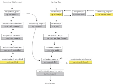
Figure 6: A function call graph in the Linux kernel for sending a packet in the TCP layer. The grey boxes are unmodified functions, and the functions in yellow are modified to handle ILNPv6 in a dual-stack operation with IPv6.
the network layer and transport-layer state for ILNP at MN can be represented by the tuple expression:
⟨𝑡𝑐𝑝 : 𝑃𝑀, 𝑃𝐶, 𝐼𝑀, 𝐼𝐶⟩ ⟨𝑖𝑙𝑛𝑝 : 𝐿1, 𝐿𝐶⟩ (3)
When the MN enters the overlapping region between cell
1 and cell 2, the value of𝐿2would be available through IPv6
RAs. The MN receives𝐿2 and now informs the CN of this
new value using a ILNPv6Locator Update (LU)message [12].
At this point, the MN could just drop the use of𝐿1(for
hard-handoff), but ILNPv6 permits a NID value to be bound to one or more L64 values simultaneously, allowing network layer soft-handoff, which minimises gratuitous packet loss during handoff. In the overlap region, the MN expression for our transport flow would now be
⟨𝑡𝑐𝑝 : 𝑃𝑀, 𝑃𝐶, 𝐼𝑀, 𝐼𝐶⟩ ⟨𝑖𝑙𝑛𝑝 : 𝐿1| 𝐿2, 𝐿𝐶⟩ (4)
It can be seen that the transport-layer tuple is not affected during handoff in ILNP: end-to-end state is preserved.
4.2. Implementation. This section explains how the Linux
kernel v3.9.0 TCP code can be modified to support ILNPv6. Figure 6 shows the functions and call graph for sending a TCP packet. First, before sending data packets, TCP requires
a connection establishment with another endpoint. The
establishment process starts at tcp v6 connect(). First,
information about the session is added to the TCP hashtable (e.g., source and destination IP address and source and
destination port number). Theinet6 ehash fn()function
was modified to use only the NID value instead of the whole IPv6 address (along with other information) for the hash calculation. This allowed received TCP/ILNPv6 packets to be deliverable to appropriate applications by using only the NID for hashtable lookup in place of the full IP address.
Sending of data packets starts with a call to the tcp sendmsg() function. The function was modified to mark the socket data structure as an ILNPv6 socket if ILNPv6 was used, using an additional flag in the socket data structure. The first step before sending a data packet is
discovering theMaximum Segment Size (MSS)available for
each packet. For ILNPv6 packets, the MSS must be reduced by 8 bytes, allowing the Nonce Destination Option [13] to be inserted into each packet. This is done by modifying tcp current mss().
net/ipv6/tcp_ipv6.c tcp_v6_rcv()
net/ipv6/tcp_ipv6.c tcp_v6_checksum_init()
include/net/inet6_hashtables.h __inet6_lookup_skb()
Network Layer
net/ipv6/tcp_ipv6.c tcp_v6_do_rcv() include/net/inet6_hashtables.h
__inet6_lookup()
net/ipv6/inet6_hashtables.c __inet6_lookup_established()
include/net/inet6_hashtables.h inet6_ehashfn()
net/ipv4/tcp_input.c tcp_rcv_established()
ESTABLISHED
net/ipv6/tcp_ipv6.c tcp_v6_hnd_req()
LISTEN
net/ipv4/tcp_minisocks.c tcp_check_req()
net/ipv6/tcp_ipv6.c tcp_v6_rtx_synack()
[image:11.600.119.480.71.521.2]net/ipv6/tcp_ipv6.c tcp_v6_send_synack()
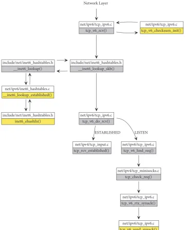
Figure 7: A function call graph in the Linux kernel for receiving a packet in the TCP layer. The grey boxes are unmodified functions, and the functions in yellow are modified to handle ILNPv6 in a dual-stack operation with IPv6.
modified to use only the NID value, instead of the whole IPv6 address, for checksum calculation. The packet would then pass to the network layer for further operations, as explained in [5].
For the receiving of a flow, the processing path of a TCP/ ILNPv6 packet is shown in Figure 7. Verified packets from
the network layer are forwarded to TCP attcp v6 rcv().
The TCP checksum calculation is performed by a modified
version of the functiontcp v6 checksum init(), again, to
allow for the use of only the NID for checksum calculation. Then, the TCP hashtable lookup is performed by the
mod-ifiedinet6 ehash fn()as stated above. After the lookup
is successful, the function inet lookup established()
determines which socket (bound to a specific application)
that the packet should be forwarded to, by comparing the provided source NID, destination NID, source port, and destination port values to ones stored in the TCP hash-table.
Once the correct socket structure is found, tcp v6
do rcv()invokes different functions depending on the TCP
state, as for IPv6. If the connection is already established,tcp
rcv established()is responsible for processing the data.
If the connection has not been established, tcp v6 hnd
4.2.1. Temporary, Practical Limitations. Since only the in-kernel, core TCP operation at the transport layer is modified
to support ILNPv6 at the moment, theGeneric Segmentation
Offload (GSO)(http://www.linuxfoundation.org/collaborate/
workgroups/networking/gso) function, including TCP
seg-mentation offload (TSO), and the TCP checksum offload, all
of which operate at the network device level, should currently
be disabled (usingethtool(8)) when using ILNPv6. These
functions are normally used on high-performance server systems, and not normally used on desktop systems or mobile/handheld devices. Also, this is a temporary measure only: of course, those functions will in due course also be modified in the appropriate device drivers to provide support for ILNPv6 before being enabled, and that is left for future work.
5. Testbed: Configuration and Metrics
Our previous work [5, 35] shows that UDP applications operating over ILNPv6 have excellent handoff performance, and the results match the feasibility study (using an overlay) that was reported in [34]. For TCP, a naive expectation would be that we would observe similar results as we have for UDP: that ILNPv6, especially, with soft-handoff, should show better performance than MIPv6 in terms of session continuity, gratuitous packet loss, and handoff delay. However, such a naive expectation does not take into account TCP’s congestion control algorithm(s), which modulate the flow transmission behaviour.
In this evaluation, MIPv6 was chosen for performance comparison against ILNPv6 for several reasons. Firstly, it is considered the standard for IP mobility. Secondly, it works with legacy applications without requiring any changes or
extensions to the currentsocket(2)API. Thirdly, there is
an existing Linux kernel implementation which can be used for direct, comparative evaluations.
For other standardised solutions listed in Section 3, there are some constraints preventing a straightforward and appro-priate comparison of application-level performance with ILNPv6, as explained below:
(1) HIP uses public keys in order to create host identities. This means that a public key infrastructure should be in place to generate host identities, and so HIP is best suited to those applications that have strin-gent requirements for the use of cryptographically verifiable identities at the network layer; this is not a general requirement for all applications. Moreover, the use of the host identity in HIP requires that
applications that use the current standard Csockets
(2) API have to be modified to operate over HIP
[47]. Legacy applications may be used, but special treatments are needed [48].
(2) SHIM6 was designed for multihoming support. There is still no standard mobility solution using SHIM6.
Also, extensions to the C sockets (2) API are
recommended [63] to allow maximal usage of the protocol.
(3) LISP was originally designed for multihoming sup-port, but can also now support mobility. The mobility extensions, both LISP-MN [23] and LISP-ROAM [44], require additional network entities to be in place, so neither present an end-to-end solution, and would require support from network service providers.
(4) PMIPv6 is a purely network-based solution, hence it has a completely different model to ILNPv6. Also, the use of a proxy does not present a transparent, end-to-end solution.
(5) MP-TCP and SCTP both operate at the transport layer only, unlike ILNPv6 and MIPv6, both of which are network layer mechanisms.
So, by using MIPv6, it is possible to use exactly the
same application binary,iperf (https://iperf.fr/) in our
exper-iments, allowing a direct and fair comparative evaluation
with ILNPv6. iperf has been widely used previously in
performance comparisons of packet flows with TCP. Note
that iperf itself can experience performance issues when
used at extremely high data rates (e.g., many 100s of Mbps, or Gbps), but our use was limited to lower data rates, as explained below.
5.1. Experiment Configuration. The network topology of the
experiment is shown in Figure 8. All systems were Gateway GR380 F1 servers with Intel Xeon 5500 series processors (note that such a relatively high specification is not necessary for running either ILNPv6 or MIPv6. This was the hardware available to us at the time of our evaluation and allowed us to execute all experiments and measurements comfortably, without the need to be concerned about the operational performance bounds of the testbed). The specifications of the machines are shown in Table 3.
The connection between the MN and the routers used IEEE 802.11ac 2x2 WLAN links. R2 and R3 used the WLAN interfaces to create 2 different wireless networks using
hostapd(http://wireless.kernel.org/en/users/Documentation
/hostapd); i.e., they acted as wireless access points. The MN had 2 wireless interfaces. The first interface was configured to connect to the network announced by R2, and the second one was for a connection to R3. The other nodes were connected by wired Ethernet 1Gbps links. All nodes ran Linux kernel
version 3.9.0.Note that R1, R2, and R3 ran a standard Linux
codebase, with no code modifications for ILNPv6 capability,
to demonstrate that ILNPv6 packets can traverse unmodified IPv6 routers. The MN and CN also ran Linux kernel version 3.9.0 but with a modified kernel to support ILNPv6, and using also the standard, kernel MIPv6 code.
5.2. Handoff in the Testbed. Movement at the IP level results
R1 CN
R3
site network L2
site network L3 site network L1
R2 (HA)
R Router
MN MobileNode
CN Correspondent Node
Agent (for MIPv6 only) Home
HA
MN MN MN Emulated
WAN Delay
[image:13.600.132.473.77.265.2]Emulated WAN Delay
Figure 8: The topology for the experiment (also as in [5]). The CN connects to R1 via 1 Gbps Ethernet. The MN initially connects to R2(HA) using 2x2 IEEE 802.11ac; the dashed/blue circles depict the radio cell scenario being emulated. The green/dashed arrows identify movements
of MN to site network𝐿3, the movements generating a handoff.
Table 3: Summary of the testbed hardware and software.
Model Gateway GR380 F1
CPU Intel Xeon E5520 @ 2.27GHz
Memory 12GB DDR3
OS
Either amodifiedLinux kernel version 3.9.0 (for MN and
CN) or withunmodifiedLinux kernel version 3.9.0 (for R1,
R2 and R3)
Ethernet driver Intel igb v4.1.2-k
Wireless adapter Edimax EW-7822UAC
Wireless driver Realtek rtl8812au v4.2.2
dynamics of a widely used radio technology to be included in our evaluation.
In real wireless scenarios and application domains, the exact dynamics of operation and performance will depend on many factors for a radio-based interface, for example,
(i) the wireless communication systems in use, such as 3G, 4G, future 5G, IEEE 802.11 variant, and so on,
(ii) the performance and quality of service (QoS) issues resulting from vertical handoff, such as between 4G and WLAN, and so on (please see Sections 7.7 and 7.8),
(iii) environmental conditions impacting radio transmis-sion, such as precipitation, foliage, building orienta-tion, obstructions, and so on,
(iv) the dynamics and nature of movement, such as speed of movement, direction of movement, especially if considering 3-dimensional movement, and not just people/vehicles along the ground, and so on,
(v) network engineering considerations, such as radio cell-size, RF channel allocation and management strategy, mobility models of users, and so on.
To account for all of these factors would obfuscate the dynamics of the network (IP) level operation. Our work is focused on a new architecture, protocol, and behaviour at the network (IP) level, so our comparison and evaluation were also at the network level protocol (and above), and not on the RF network radio technologies. Indeed, IP, by its initial design and philosophy, operates independently of any subnetwork technology, and so the design and evaluation of any IP-level mechanisms should not be dependent on any lower-layer technologies.
Of course, we would expect that if ILNP were to be considered for a real scenario or application domain, it would be vital to undertake the usual engineering practices before deployment, as required. This would include extensive site-surveys and suitable tests to establish absolute performance capability and to enable an appropriate network configura-tion to be defined.
5.3. Handoff Scenarios. Different network conditions for
handoff scenarios were emulated usingnetem (http://www
[image:13.600.49.549.338.456.2]use ofnetemis convenient and appropriate for our particular experiment, as it was not our intention to carry-out high-performance/stress tests of TCP. Four MN handoff scenarios were created as follows:
(1) LAN to LAN:netemdisabled
(2) LAN to WAN:netemenabled between R1 and R3
(3) WAN to LAN:netemenabled between R1 and R2
(4) WAN to WAN:netem enabled both between R1 and
R2 and between R1 and R3
TCP flows were generated from the CN to the MN
using iperf version 2.0.5. All TCP flows used the default
values iniperf except that the TCP window size was limited
to 320 Kbytes. In our initial experiments, we found that without this constraint, the CN could generate a localised congestion effect: TCP packets were queued at the MN, and in some cases prevented RA packets from being delivered
in a timely manner. Note that this is not a constraint of
either ILNPv6 or MIPv6, but was a pathological condition
of our testbed only.Eventually, a handoff, for both ILNPv6
and MIPv6, could be improperly triggered because the MN had not seen an RA from its current access router during a certain period of time, so the old L64 value (IPv6 prefix) was considered to be stale. For ILNPv6, the problem can be fixed by increasing the lifetime of an L64 value, so that the delayed RA does not trigger a handoff. However, in MIPv6 the handoff model is more complicated, and tuning MIPv6 to be able to operate under this specific circumstance was out of scope of this work. Therefore, limiting the TCP window size to constrain the amount of TCP traffic for both MIPv6 and ILNPv6 was the most appropriate approach to allow a direct performance comparison of MIPv6 and ILNPv6 under the same conditions, with default OS end-system configuration.
Each TCP flow lasted 30 seconds and was repeated 10 times for MIPv6 (with and without RO enabled), as well as for
ILNPv6 hard-handoff and soft-handoff:tcpdumpwas used to
capture packets at the MN and at the CN forpost hocanalyses.
In Figure 8, the MN started in site network 𝐿2, which
was the home network for MIPv6. Theiperf TCP flows were
transmitted from the CN to the MN. The MN started to enter
the site network𝐿3at t=5s, and moved out of the site network
𝐿2at t=20s. The movement was emulated using controlled,
scripted invocations ofifconfigto bring the WLAN interfaces
up and down. The tests were executed for each of the 4 handoff scenarios mentioned above: LAN to LAN, LAN to WAN, WAN to LAN, and WAN to WAN.
5.4. Measurements and Metrics. We used four performance
metrics, as listed below.
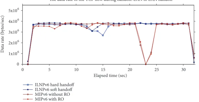
(1) TCP flow data rate: TCP flow data rate graphs of different handoff scenarios are presented. This is to visualise how handoff by ILNPv6 and MIPv6 impacts ened-to-end TCP performance. A handoff without an interruption in the flow is ideal.
(2) Successfully transferred data: volume of bytes of data that can be sent during the 30 second flow. The
more the data that can be sent, the better the TCP performance. This was a long enough duration to cover the handoff period and to allow TCP congestion control algorithms to operate.
(3) Retransmissions: number of TCP retransmissions attempted by the CN in each flow. The retransmis-sions are usually caused by packet loss but could also be caused by packet errors and misordering. The lower the number of retransmissions, the better the TCP performance.
(4) Packet loss: number of lost packets in the flows. Lower values are better; zero is ideal.
(5) Handoff delay: the time that the MN needs to com-plete the handoff process. Lower values are better; the minimum (ideal) time will be a single round trip time (RTT) between MN and CN.
In our results, where we have error bars, they are small, so the results are statistically sound; and in some results we have used box-plots in order to show clearly the distribution and variation of the results.
6. Evaluation: Results and Analyses
This section presents TCP performance over ILNPv6 and MIPv6. In general, our findings are that ILNPv6 performs better than MIPv6 in nearly all cases. We compare directly for each scenario (as described in Section 5.3) and for each metric (as described in Section 5.4).
6.1. TCP Flow Data Rate Behaviour. This section presents
how the overall TCP flow data rate behaves in each handoff scenario. For each handoff scenario, one of ten repetitions is selected as an example of the time-domain flow dynamics that are typically observed. The TCP throughput is limited by the TCP window size and is calculated as in [64]
𝑀𝑎𝑥𝑖𝑚𝑢𝑚 𝑇𝐶𝑃 𝑡ℎ𝑟𝑜𝑢𝑔ℎ𝑝𝑢𝑡
= 8 × 𝑇𝐶𝑃 𝑤𝑖𝑛𝑑𝑜𝑤 𝑠𝑖𝑧𝑒
𝑅𝑇𝑇
(5)
So, with a 320 Kbyte window (see above), the maximum
TCP throughput in the LAN environment, which has RTT=∼
5 ms, is(8 × 320)/5 = 512Mbps (64 Mbytes/s). However, this
high rate cannot be achieved due to the limited link speed of the WLAN links. The observed throughput in the LAN is around 30 Mbps (3.75 Mbytes/s). For the WAN environment,
with RTT ∼200 ms, the throughput has a ceiling of (8 ×
320)/200 = 12.8Mbps (1.6 Mbytes/s).
0 5 10 15 20 25 30 Elapsed time (sec)
The data rate of the TCP flow during handoff: LAN to LAN handoff
ILNPv6 hard handoff ILNPv6 soft handoff MIPv6 without RO MIPv6 with RO 0
1x10⁶
2x10⁶
3x10⁶
4x10⁶
5x10⁶
D
at
a ra
te (b
yt
es/s
[image:15.600.128.476.78.257.2]ec)
Figure 9: Typical profile for a TCP flow showing the data rate (bytes/sec) at the MN, with LAN to LAN handoff. There was an interruption during the MN handoff for MIPv6, while there was a small drop in data rate for ILNPv6.
0
1x10⁶
2x10⁶
3x10⁶
4x10⁶
5x10⁶
0 5 10 15 20 25 30
D
at
a ra
te (b
yt
es/s
ec)
Elapsed time (sec)
The data rate of the TCP flow during handoff: LAN to WAN handoff
ILNPv6 hard handoff ILNPv6 soft handoff MIPv6 without RO MIPv6 with RO
Figure 10: Typical profile for a TCP flow showing the data rate (bytes/sec) at the MN, with LAN to WAN handoff. There was an interruption during the MN handoff for MIPv6 and ILNPv6 hard-handoff, while there was no interruption for ILNPv6 soft-handoff. The data rate dropped after the handoff due to higher end-to-end delay.
the Duplicate Address Detection (DAD) before a handoff for ILNPv6 was triggered.
The key finding is that ILNPv6 with soft-handoff per-formed better than MIPv6 because the TCP flow was not interrupted when a handoff occurred, but MIPv6 suffered disruption to the flow, including large drops in throughput (sometimes down to zero throughput for several seconds). The detailed analysis of the flows in each handoff scenario is given below.
LAN to LAN Handoff. As shown in Figure 9, in the LAN
environment, in the MIPv6 case, there was an interruption during the MN handoff, where the throughput dropped to zero. There was no difference between MIPv6 with and without RO enabled: the interruption time was similar, equal to the time that was used to update the HA. On the other hand, there was no interruption for ILNPv6, but there was a
small drop in throughput during handoff. There was a slightly greater drop in throughput using hard-handoff compared to soft-handoff. This result shows that TCP is more sensitive than UDP since, for UDP, we observed no loss and no drop in throughput during soft-handoff in our previous work [5]. The drop in throughput was caused by TCP retransmissions because of packet misordering (see Section 6.1.2 for more details).
LAN to WAN Handoff. From Figure 10, we observe that,
[image:15.600.127.473.308.485.2]0 5 10 15 20 25 30 Elapsed time (sec)
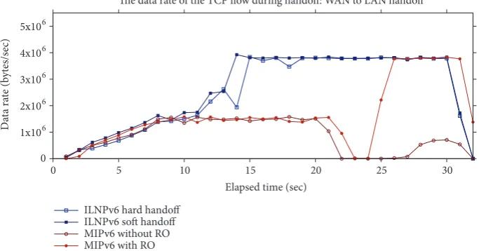
The data rate of the TCP flow during handoff: WAN to LAN handoff
ILNPv6 hard handoff ILNPv6 soft handoff MIPv6 without RO MIPv6 with RO 0
1x10⁶
2x10⁶
3x10⁶
4x10⁶
5x10⁶
D
at
a ra
te (b
yt
es/s
[image:16.600.129.471.77.256.2]ec)
Figure 11: Typical profile for a TCP flow showing the data rate (bytes/sec) at the MN, with WAN to LAN handoff. There was an interruption during the MN handoff for MIPv6, while there was no interruption for ILNPv6. The data rate increased after the handoff due to a lower delay link, except MIPv6 without RO, where the traffic still traversed the high-delay link because of the tunnel to the HA.
0 5 10 15 20 25 30
Elapsed time (sec)
The data rate of the TCP flow during handoff: WAN to WAN handoff
ILNPv6 hard handoff ILNPv6 soft handoff MIPv6 without RO MIPv6 with RO 0
1x10⁶
2x10⁶
3x10⁶
4x10⁶
5x10⁶
D
at
a ra
te (b
yt
es/s
ec)
Figure 12: Typical profile for a TCP flow showing the data rate (bytes/sec) at the MN, with WAN to WAN handoff. There was an interruption during the MN handoff for MIPv6 and ILNPv6 hard-handoff, while there was no interruption for ILNPv6 soft-handoff.
worse than the LAN-LAN handoff. There was no significant difference observed for MIPv6 whether RO was enabled or not.
ILNPv6 hard-handoff had a small interruption in the flow, but a much shorter period than MIPv6. For ILNP soft-handoff, there was no interruption. The throughput degraded gradually, consistent with normal TCP behaviour, due to the handoff to a link with a higher end-to-end delay.
WAN to LAN Handoff. The TCP flows in this handoff scenario
showed an opposite trend to the previous one. The TCP throughput increased after the MN handoff from the WAN network to the LAN network, as displayed in Figure 11. However, this was not true for MIPv6 without RO, because the traffic still had to traverse the HA, which resided across the WAN link. ILNPv6 with soft-handoff still showed the best behaviour: the flow gradually increased without any
interruption, as the TCP algorithm adjusted to the lower RTT.
For both ILNPv6 and MIPv6, the throughput at the beginning of the flow was quite low, and it gradually increased. This was caused by the TCP slow start mechanism [65]. Due to the high-delay link, the slow start process took some time before reaching threshold when the maximum data rate could be achieved. The slow start process was much faster in the LAN environment: it can be seen in Figures 9 and 10 that TCP throughput climbed faster at the beginning of the flows, which was to be expected as normal TCP behaviour.
WAN to WAN Handoff. ILNPv6 with soft-handoff still
[image:16.600.129.471.317.496.2]MIP without_RO
MIP with_RO
ILNPv6 hard_handoff
ILNPv6 soft_handoff The amount of transferred data during the 30 second TCP flow,
LAN to LAN handoff
0 20 40 60 80 100
T
ra
n
sf
er
re
d da
ta (MB)
(a) LAN to LAN handoff
MIP without_RO
MIP with_RO
ILNPv6 hard_handoff
ILNPv6 soft_handoff The amount of transferred data during the 30 second TCP flow,
LAN to WAN handoff
0 20 40 60 80 100
T
ra
n
sf
er
re
d da
ta (MB)
(b) LAN to WAN handoff
MIP without_RO
MIP with_RO
ILNPv6 hard_handoff
ILNPv6 soft_handoff The amount of transferred data during the 30 second TCP flow,
WAN to LAN handoff
0 20 40 60 80 100
T
ra
n
sf
er
re
d da
ta (MB)
(c) WAN to LAN handoff
MIP without_RO
MIP with_RO
ILNPv6 hard_handoff
ILNPv6 soft_handoff The amount of transferred data during the 30 second TCP flow,
WAN to WAN handoff
0 20 40 60 80 100
T
ra
n
sf
er
re
d da
ta (MB)
[image:17.600.67.530.75.355.2](d) WAN to WAN handoff
Figure 13: Total data transfer volumes during 30 second TCP traffic flows. With ILNPv6, TCP can transfer more data than with MIPv6 in almost every case, except when using handoff from LAN to WAN, because the MN uses the LAN link longer when MIPv6 is used.
interruption was observed. Moreover, the MN suffered the most when RO was disabled, as might be expected. After the handoff, the throughput was very poor because the traffic traversed the HA over a WAN link and was then forwarded to the MN via another WAN link. So, the RTT was high, and TCP had unsatisfactory performance. Again, TCP slow start can be observed at the beginning of the flows.
6.1.1. Successfully Transferred Data. Figure 13 shows the
amount of data (in MB) that was transferred during the 30 second TCP flow using ILNPv6 and MIPv6 under different handoff scenarios. In a LAN-LAN environment, TCP sent the greatest amount of data because the RTT was low, and so the TCP throughput was high; TCP throughput and RTT are inversely proportional [64]. Therefore, in the WAN network (higher RTT), TCP sent less data.
In most cases, more data was sent when ILNPv6 was used, compared to MIPv6, because the data was sent without interruption (soft-handoff) or minimal interruption (hard-handoff); see Section 6.1. However, this was not true for the LAN to WAN handoff: more data was sent when MIPv6 was used. As mentioned previously, for ILNPv6, the handoff to the WAN network occurs when the MN enters the overlap area (t=5s, in this experiment). So, the MN spent a much longer time on the WAN network when using ILNPv6 than when using MIPv6, which hands off to the WAN network after it moves out of the LAN network (t=20s, in this experiment). Assuming that more data can be sent in the LAN network, it is understandable that MIPv6 allowed more data to be sent in
this case. This is pathological to our experimental scenario, and MIPv6 has not been designed specifically to optimise handoff performance in such scenarios. Hence, to maximise TCP performance, an adjustment to the ILNPv6 or MIPv6 handoff decision algorithm may be required, e.g., let the MN stay on a ‘better’ link as long as possible before handoff. Of course, this may need information from the link layer, e.g., signal strength or other quality of service indicators. Similarly, in the WAN to LAN handoff case, a lot more data was sent for ILNPv6, partly because the MN stayed in the LAN network longer than in the MIPv6 case.
For MIPv6, RO improved the amount of data that was sent if the HA resided in the WAN network (i.e., the WAN to LAN handoff and WAN to WAN handoff cases). When RO is disabled, data packets must traverse the high-delay WAN link to the HA, causing an increase in RTT and hence lower data rate. This was avoided when RO was enabled, so the data rate improved.
6.1.2. Retransmissions Attempted. The number of TCP
retransmissions in each handoff scenario is shown in Figure 14. This number was measured at the CN by counting sent packets having the same TCP sequence number.
MIPv6
without RO with ROMIPv6 ILNPv6 hard ILNPv6 soft
Handoff delay from LAN to LAN for TCP flow
0 500 1000 1500 2000 2500 3000
D
ela
y [m
s]
(a) LAN to LAN handoff
MIPv6
without RO with ROMIPv6 ILNPv6 hard ILNPv6 soft
Handoff delay from LAN to WAN for TCP flow
0 500 1000 1500 2000 2500 3000
D
ela
y [m
s]
(b) LAN to WAN handoff
MIPv6 without RO
MIPv6 with RO
ILNPv6 hard
ILNPv6 soft Handoff delay from WAN to LAN for TCP flow
0 500 1000 1500 2000 2500 3000
D
ela
y [m
s]
(c) WAN to LAN handoff
MIPv6 without RO
MIPv6 with RO
ILNPv6 hard
ILNPv6 soft Handoff delay from WAN to WAN for TCP flow
0 500 1000 1500 2000 2500 3000
D
ela
y [m
s]
[image:18.600.81.517.69.396.2](d) WAN to WAN handoff
Figure 14: Number of retransmissions attempted at the CN. ILNPv6 with soft-handoff had the lowest number of retransmissions.
close to zero retransmissions because almost zero packet loss occurred. However, ILNPv6 had a larger number of retransmissions than expected. For hard-handoff, the num-bers were close to the MIPv6 case. For soft-handoff, a lower number of retransmissions were observed than for MIPv6, and the numbers were quite low during the MN handoff to the WAN network. These retransmissions were caused by packet queuing and misordering from intense TCP traffic; see below for further information in each scenario.
In the LAN to LAN handoff scenario, the TCP traffic
rate was high (∼30Mbps), so some packets were queued at
the MN before getting processed. When a handoff occurred, for the ILNPv6 case, packets that came via the new link did not see any queue, and were thus processed before the queued packets at the old link. Therefore, TCP received packets with a ‘jump’ in sequence number, and duplicate acknowledgements were sent back to the CN because the MN interpreted this sequence number jump (packet reordering) as packet loss. Finally, the CN, which received many duplicate acknowledgements, had to retransmit packets which were in fact queued at the old link. Note that this response to sequence number jumps and duplicate acknowledgements is normal TCP behaviour, the fast retransmit/fast recovery mechanism [65, Section 3.2]. For hard-handoff, a similar situation occurred, but all queued packets at the MN would eventually be dropped at the network layer due to their stale L64 value.
For the WAN to LAN handoff scenario, similar behaviour was also observed for a similar reason: after handoff, packets arrived at the new link before packets from the old link got processed. However, this was not because of a queue at the old link—since the TCP throughput in the WAN link is not as high as in the LAN (less than 12.8Mbps, see the calculation above in Section 6.1)—but because the new link has much lower delay.
For the LAN to WAN case, ILNPv6 with soft-handoff had a lower number of retransmissions. This is because, after handoff, the new link was much slower than the old link, so quite a small number of packets arrived at the new link, while the packets from the old link were queued, and fewer duplicate acknowledgements were sent to the CN. ILNPv6 with hard-handoff still had some retransmissions owing to packet loss during handoff.
For the WAN to WAN handoff case, ILNPv6 with soft-handoff, again, had a very low number of retransmissions, almost zero. As mentioned before, the TCP traffic in the WAN is of a lower rate than in the LAN, so the problem of queued packets was not observed. For ILNPv6 with hard-handoff, again, some retransmissions were observed due to packet loss during handoff.
![Table 1: Use of names in IP and ILNP (modified from [7].).](https://thumb-us.123doks.com/thumbv2/123dok_us/8700224.381316/3.600.50.552.89.152/table-use-names-ip-ilnp-modified.webp)

![Figure 8: The topology for the experiment (also as in [5]). The CN connects to R1 via 1 Gbps Ethernet](https://thumb-us.123doks.com/thumbv2/123dok_us/8700224.381316/13.600.49.549.338.456/figure-topology-experiment-cn-connects-r-gbps-ethernet.webp)