(;%PP&DUWULGJH7DSH
6XEV\VWHP
Copyright
Copyright 1990 by EXABYTE Corporation. All rights reserved. This item and the information contained herein are the property of EXABYTE Corporation. No part of this document may be reproduced, transmitted, transcribed, stored in a retrieval system, or translated into any language or computer language in any form or by any means, electronic, mechanical, magnetic, optical, chemical, manual or otherwise, without the express written permission of EXABYTE Corporation, 1745 38th Street, Boulder, Colorado 80301.
Disclaimer
EXABYTE Corporation makes no representation or warranties with respect to the contents of this document and specifically disclaims any implied warranties of merchantability or fitness for any particular purpose. Further, EXABYTE Corporation reserves the right to revise this publication and to make changes in it from time to time without obligation of EXABYTE Corporation to notify any person or organization of such revision or changes.
Trademark Notices
Revision History
Revision No. Date Revision Information
000 January 1989 Preliminary version.
Table of Contents
1 General Information . . . 1
1.1 About This Manual . . . 1
1.1.1 Intended Audience . . . 1
1.1.2 Related Publications . . . 1
1.1.3 Revisions . . . 2
1.2 Static Protection Requirements . . . 2
1.3 Test and Repair Environment . . . 3
1.4 Required Test Tapes . . . 4
1.5 Required Tools and Test Equipment . . . 5
1.5.1 Tools . . . 5
1.5.2 Test Equipment . . . 5
1.5.3 Software . . . 6
1.5.4 Supplies . . . 6
1.6 EXB-8200 Unit Test . . . 6
1.6.1 Preparation . . . 6
1.6.2 Testing the EXB-8200 . . . 6
2 Adding and Removing an EXB-8200 in the Test and Repair Environment . . . 9
2.1 Adding an EXB-8200 to the Test Environment . . . 9
2.2 Removing an EXB-8200 from the Test Environment . . . 13
3 R-Pack Removal and Replacement . . . 15
3.1 R-Pack Configurations . . . 15
3.2 DIP Mounted R-Pack Removal . . . 15
3.3 DIP Mounted R-Pack Installation . . . 15
3.4 SIP Mounted R-Pack Removal . . . 17
3.5 SIP Mounted R-Pack Installation . . . 17
4 Top Cover Removal and Replacement . . . 19
4.1 Top Cover Removal . . . 19
6 Card Retainer Removal and Replacement . . . 25
6.1 Preparation . . . 25
6.2 Remove Card Retainers . . . 25
6.3 Replace Card Retainers . . . 25
6.4 Reassemble the EXB-8200 . . . 25
7 Deck Hanger Removal and Replacement . . . 27
7.1 Preparation . . . 27
7.2 Deck Hanger Removal . . . 27
7.3 Deck Hanger Replacement . . . 27
7.4 Reassemble the EXB-8200 . . . 28
8 Edge Connector Mounted Card Removal and Replacement . . . 29
8.1 MX Card Compatibility . . . 29
8.2 Preparation . . . 29
8.3 Proper Handling of Printed Circuit Cards . . . 31
8.4 Edge Connector Mounted Card Removal . . . 31
8.5 RW Card Connections . . . 33
8.6 Replace Edge Connector Mounted Cards . . . 33
8.7 Reassemble the EXB-8200 . . . 33
9 SV Card Removal and Replacement . . . 35
9.1 Preparation . . . 35
9.2 Proper Handling of Printed Circuit Cards . . . 35
9.3 Remove Mounting Screws . . . 35
9.4 Disconnect SV Card Connectors . . . 37
9.5 Reconnect the SV Card Connections . . . 40
9.6 Reattach the SV Card to the Main Housing . . . 40
9.7 Reassemble the EXB-8200 . . . 41
10 MX EPROM Removal and Replacement . . . 43
10.1 Preparation . . . 43
10.2 Identification Information . . . 43
10.3 EPROM Removal . . . 45
10.4 EPROM Installation . . . 47
10.5 Reassemble the EXB-8200 . . . 49
11 SV Card EPROM Removal and Replacement . . . 51
11.1 Proper Handling of Printed Circuit Cards . . . 51
11.3 EPROM Removal for SV Card 721103-Bxx . . . 51
11.4 Preparation for SV Card 721102-Bxx . . . 53
11.5 EPROM Removal for SV Card 721102-Bxx . . . 53
11.6 EPROM Installation . . . 53
11.7 Reassemble the EXB-8200 . . . 55
12 Faceplate Removal and Replacement . . . 57
12.1 Faceplate Removal . . . 57
12.2 Faceplate Replacement . . . 59
13 Door Removal and Replacement . . . 61
13.1 Preparation . . . 61
13.2 Door Removal . . . 61
13.3 Door Replacement . . . 63
14 Deck Assembly Removal and Replacement . . . 65
14.1 Preparation . . . 65
14.2 Deck Removal . . . 65
14.3 Deck Replacement . . . 67
14.4 Reassemble the EXB-8200 . . . 67
15 Main Housing Removal and Replacement . . . 69
15.1 Preparation . . . 69
15.2 Main Housing Removal . . . 69
15.3 Main Housing Replacement . . . 70
15.4 Reassemble the EXB-8200 . . . 70
16 Cleaning Procedure . . . 71
16.1 Accepted Procedures and Products . . . 71
16.2 Cleaning Intervals . . . 71
16.3 Minimum Firmware Level Required . . . 71
16.4 Cleaning Action Performed by Cartridge . . . 72
16.5 Usage and Reusage . . . 72
17.5 Preparation of the EXB-8200 . . . 75
17.6 Cartridge Preparation . . . 75
17.7 Erase Head Bracket Removal . . . 77
17.8 Tape Guide Removal . . . 77
17.9 Tape Removal . . . 79
17.10 Remove Faceplate and Open Door . . . 81
17.11 Wind Loose Tape and Eject Data Cartridge . . . 81
17.12 Reassemble the EXB-8200 . . . 82
18 Head Sync Adjustment Procedure . . . 83
18.1 Requirements . . . 83
18.1.1 Tools . . . 83
18.1.2 Test Equipment . . . 83
18.1.3 Software and User’s Manuals . . . 85
18.2 Preparation . . . 85
18.3 Scope Settings . . . 87
18.4 Check the Head Sync Timing . . . 87
18.5 Adjust the Head Sync Timing . . . 91
18.6 Verify the Adjustment . . . 92
Figures
Figure 2-1 Connector and Switch Locations for the DB Card . . . 8
Figure 2-2 Location of DIP Switches and Remote Connector on DS Card . . . 8
Figure 2-3 SCSI ID DIP Switch Settings for the DB and DS Cards . . . 10
Figure 2-4 SCSI ID Jumper Connections for the DR Card . . . 10
Figure 2-5 SCSI ID Jumper Connections for the DS Card . . . 10
Figure 2-6 Location of the Unload Button . . . 12
Figure 3-1 Location of DIP R-Packs on Rear of EXB-8200 . . . 14
Figure 3-2 Location of SIP R-Packs on Rear of EXB-8200 . . . 16
Figure 4-1 Location of Screws in Top Cover . . . 18
Figure 4-2 Location of Screws in Top Cover (same as Figure 4-1) . . . 20
Figure 5-1 Location of Screws in the SV Card Cover . . . 22
Figure 6-1 Location of Card Retainers (deck hanger not shown) . . . 24
Figure 7-1 Location of Deck Hanger . . . 26
Figure 8-1 Location of Edge Connector Mounted Cards . . . 30
Figure 8-2 Location of RW Card Wire Harness Connections . . . 32
Figure 9-1 Location of SV Card Mounting Screws . . . 34
Figure 9-2 Location of SV Card Connectors . . . 36
Figure 9-3 Connector Key Sockets . . . 38
Figure 10-1 Location of Edge Connector Mounted Cards . . . 42
Figure 10-2 Location of EPROM for MX, MS, or MV Cards . . . 44
Figure 10-3 Location of EPROM for MX and MS Cards . . . 44
Figure 10-4 Location of EPROM for MX, MS, or MV Cards (same as Figure 10-2) . . . 46
Figure 10-5 Location of EPROM for MX and MS Cards (same as Figure 10-3) . . . 46
Figure 10-6 Location of Edge Connector Mounted Cards . . . 48
Figure 11-1 Location of SV Card EPROM for SV Card 721103-Bxx . . . 50
Figure 11-2 Location of SV Card EPROM for SV Card 721102-Bxx . . . 52
Figure 13-3 Relationship among the Door, Door Retainer, and Door Bracket . . . 62
Figure 14-1 Location of Deck Mounting Screws . . . 64
Figure 14-2 Location of Deck Mounting Screws (same as Figure 14-1) . . . 66
Figure 15-1 Main Housing Removal . . . 68
Figure 17-1 Data Cartridge with Door Taped Open . . . 74
Figure 17-2 EXB-8200 with Tape Loaded . . . 76
Figure 17-3 EXB-8200 with Tape Loaded . . . 78
Figure 17-4 EXB-8200 with Tape Loaded (same as Figure 17-3) . . . 80
Figure 18-1 Oscilloscope Connections for the Head Sync Timing Procedure . . . 84
Figure 18-2 Waveforms . . . 86
Figure 18-3 Waveforms (same as Figure 18-2) . . . 88
Figure 18-4 Waveforms (same as Figure 18-2) . . . 90
Tables
Table 2-1 Pin Assignments on the Remote Connector . . . 111 General Information
The EXB-8200 8mm Cartridge Tape Subsystem Maintenance Manual de-scribes how to repair or test an EXABYTE™ EXB-8200 8mm Cartridge Tape Subsystem (EXB-8200).
1.1 About This Manual
This manual contains 18 sections. Section 1 provides general information that you need to know before you begin testing or repairing the EXB-8200, includ-ing information about the followinclud-ing:
Static protection requirements The test and repair environment Required test tapes
Required tools and test equipment Related publications
Performing an EXB-8200 unit test.
Sections 2 through 18 of this manual describe how to repair, maintain, and test the EXB-8200. Each section describes the preparation needed for each task and then provides step-by-step instructions for completing the task.
The instructions in each section of this manual are organized so that all fig-ures appear on a left-hand page and the associated descriptions appear on the adjacent right-hand page. If the description associated with a figure continues beyond a single page, the figure is repeated.
1.1.1 Intended Audience
This manual is provided to assist EXABYTE Self Maintenance Contract Cus-tomers in the repair and testing of the EXB-8200.
1.1.2 Related Publications
The following manuals and user’s guides are referred to in this manual. These manuals and guide books are necessary to understand and accomplish some of the tasks referred to in this manual.
Monitor User’s Guide for the EXB-8200 8mm Cartridge Tape Subsystem, 510009
EXPERT User’s Guide for the EXB-8200 8mm Cartridge Tape Subsystem, 510010.
The following books are also useful in understanding the EXB-8200, and it is recommended that they be kept with this manual:
EXB-8200 8mm Cartridge Tape Subsystem Theory of Operations, 510007
EXB-8200 8mm Cartridge Tape Subsystem Illustrated Parts Catalog, 510000.
1.1.3 Revisions
This document may be revised in whole or in part at any time. If only a sin-gle section is revised or added, only those pages will be distributed to the reg-istered holders of this manual.
1.2 Static Protection Requirements
The test and repair environment for the EXB-8200 must be free of conditions that could cause electrostatic discharge (ESD). To ensure that the testing envi-ronment is as free from ESD as possible, follow these procedures when test-ing and repairtest-ing the EXB-8200:
Place a static protection mat on the work surface used for testing and re-pairing the EXB-8200. Use a 1-megohm resistor to ground the static pro-tection mat.
Ensure that the power supply connected to the EXB-8200 is properly grounded.
Ensure that the personal computer used for EXPERT and Monitor soft-ware and for the SCSI bus is properly grounded.
Wear a static protection wrist band whenever you handle the EXB-8200 or EXB-8200 cards that have been removed from their antistatic bags. Connect this wrist band to the static protection mat or to other suitable ESD grounding.
1.3 Test and Repair Environment
The environment for testing or repairing the EXB-8200 consists of the follow-ing:
A work area set up with static protection as described in Section 1.2 of this manual.
A power supply that conforms to the requirements of the EXB-8200 8mm Cartridge Tape Subsystem Product Specification for each EXB-8200 un-der test.
An IBM or compatible personal computer system with a color monitor and serial port.
An Adaptec SDS-1 family or SDS-3 family SCSI controller or an Ad-vanced Storage Concepts ASC-88 SCSI controller installed in the com-puter system.
A SCSI bus cable properly connected to the Adaptec or ASC-88 controller and properly terminated.
An EXABYTE Monitor cable (727005) connected to the serial communi-cations port on the computer system.
EXABYTE Monitor software (version 9.12 or later) loaded on the com-puter system.
EXABYTE EXPERT software (version 6.30 or later) loaded on the com-puter system.
Any other equipment that may be required or specified in testing specifica-tions and procedures published by EXABYTE.
Note: There are no exceptions to the environmental requirements unless
spe-cifically agreed to in writing by the customer and EXABYTE. Such an agreement will become part of this manual as an addendum to this section.
1.4 Required Test Tapes
This section describes the tapes that are required to test the EXB-8200 and the methods to be followed in creating them. Label these tapes appropriately for easy identification.
Test tape
Read Interchange test tape Write Interchange test tape
EXABYTE Head Sync Tapes (180223), where applicable.
Test Tape
The test tape is used for all testing with EXPERT test software. It should be an EXATAPE™ 112m tape.
Read Interchange Test Tape
The tape used for the Read Interchange test should be an EXATAPE 15m tape. This tape is written by the EXPERT Inter_chg test on a known good drive.
Write Interchange Test Tape
The tape used for the Write Interchange test should be an EXATAPE 15m tape. This tape is written by the EXPERT Inter_chg test on the drive being tested. It is read by a known good drive to verify interchangeability.
EXABYTE Head Sync Tapes
At least two head sync tapes are required to adjust the head sync any time an SV card or deck is replaced.
1.5 Required Tools and Test Equipment
This section describes the tools and test equipment required to test and repair the EXB-8200.
1.5.1 Tools
The following tools are necessary to work on the EXB-8200:
T8 - TORX® screwdriver T10 - TORX screwdriver
Torque measuring screwdriver (1.0 to 5.0 inch-pounds) Tweezers
EPROM chip puller
Small straight blade screwdriver - # 0
Small cross blade (Phillips) screwdriver - # 1 SCSI bus cable
Monitor cable (727005) EPROM chip installation tool Needle nose pliers
Nonconductive tool, such as a molded potentiometer adjustment tool.
1.5.2 Test Equipment
The following test equipment is necessary to work on EXABYTE products:
Two channel oscilloscope (50 MHz with time delay capability) with a hood.
Regulated +5/+12 VDC power supply.
IBM or compatible personal computer system with a color monitor and se-rial port.
Adaptec SDS-1 family or SDS-3 family SCSI controller or an Advanced Storage Concepts ASC-88 SCSI controller installed in the computer sys-tem.
1.5.3 Software
The following software is recommended to test the EXB-8200:
EXPERT Version 6.30 or later.
Runtime For Adaptec SDS-1 family SCSI controllers. The Runtime executable file is provided by Adaptec when the controller is purchased. Adaptec SDS-3 family and ASC-88 SCSI controllers do not need any special software.
Monitor Version 9.12 or later.
1.5.4 Supplies
The following supplies are necessary for testing, repairing, and maintaining the EXB-8200:
Test tapes (see Section 1.4 for descriptions)
EXABYTE 8mm Tape Subsystem Cleaning Cartridge (727113)
Threebond screwlocking agent (item number 1401B)
Loctite® X-NMS Cleanup Solvent (item number 76820).
1.6 EXB-8200 Unit Test
This section describes how to test an EXB-8200 to determine functionality and to evaluate its performance when troubleshooting.
1.6.1 Preparation
Read Sections 1 and 2 of this manual and the EXPERT User’s Guide for the EXB-8200 8mm Cartridge Tape Subsystem before testing any EXB-8200.
1.6.2 Testing the EXB-8200
All the tests listed in the EXPERT User’s Guide are useful for evaluating per-formance of the EXB-8200. Each test was written to evaluate perper-formance of the EXB-8200 while doing specific types of operations. See the EXPERT User’s Guide for details.
spikes. Power problems will typically cause a high percentage of ECC or ex-treme difficulty getting known good EXB-8200s to pass the tests consistently.
Test tapes should be closely monitored to ensure that any failures reported by EXPERT are EXB-8200 related rather than tape related. In the event of a me-dia error, rerun the test with a known good tape to verify the failure.
To ensure accuracy and consistency when testing a string of EXB-8200s, start all EXB-8200s at the same time and run them without interruption to comple-tion. Doing this reduces the likelihood of operator error and computer soft-ware hangs. Many hours of testing can be negated by a simple operator error.
Figure 2-1
[image:18.612.167.422.72.368.2]Connector and Switch Locations for the DB Card (single-ended SCSI)
Figure 2-2
2 Adding and Removing an EXB-8200 in the Test and
Re-pair Environment
This section describes how to add an EXB-8200 to or remove it from the test and repair environment described in Section 1.3. Follow this procedure to pre-vent possible problems for the other devices being tested on the SCSI bus.
2.1 Adding an EXB-8200 to the Test Environment
When there is an available address on the SCSI bus and tests are being per-formed on other EXB-8200s attached to the bus, follow these steps to add a new EXB-8200 to the bus.
IMPORTANT
These steps assume that each EXB-8200 has its own power supply. If more than one EXB-8200 share the same power supply, adding an EXB-8200 to the power supply’s load may momentarily drop the 5 volt power level below 4.7 volts, which will reset the SCSI bus. Us-ing individual, switched power supplies for each EXB-8200 under test helps eliminate possible interference.
1. Stop SCSI bus activity by pressing the function key corresponding to the SCSI ID for the available position in the EXPERT display. Refer to the EXPERT User’s Guide for instructions.
2. If you are using a single-ended SCSI configuration, remove the resistor terminator packs (R-packs) from the EXB-8200. See Section 3.
Figure 2-5
SCSI ID DIP Switch Settings for the DB and DS Cards
Figure 2-3
SCSI ID Jumper Connections for the DR Card
Figure 2-4
SCSI ID Jumper Connections for the DS Card (implemented for embed 3)
4. Using the appropriate method for your configuration, set the SCSI ID to the proper address for the available position in the EXPERT display. Figure 2-3 shows the ID settings for the DIP switches on the DB or DS card. Figure 2-4 shows the jumper settings for the DR card, while Figure 2-5 shows the jumper settings for DS cards with remote connectors.
Table 2-1 shows the pin assignments for the remote connector. Note that the switch settings for the remote connector should emulate the jumper positions shown in Figure 2-4 and Figure 2-5.
Pin Signal
1 SCSI ID Bit 2 (MSB)
2 Ground
3 SCSI ID Bit 1
4 Ground
5 SCSI ID Bit 0 (LSB)
6 Ground
IMPORTANT
If you are using a remote switch or jumpers to set the SCSI ID on the DS card, make sure that the DIP switches are set to address 0. Simi-larly, if you are using the DIP switches to set the SCSI ID, make sure that the remote switch or jumpers are set to address 0. If you set both the DIP switches and the remote switch to a particular address, the ac-tual SCSI ID will be the logical OR of the two settings.
Table 2-1
Pin Assignments on the Remote Connector
Figure 2-6
Location of the Unload Button
5. Ensure that the power is interrupted (off) so that the power cable can be connected to the EXB-8200 being tested.
6. Connect the EXB-8200 to the power supply.
7. Turn on the power supply.
Note: Do not apply power to an EXB-8200 with the SCSI bus connected, or
a SCSI bus reset or error condition may result.
8. Connect the EXB-8200 to the SCSI bus cable.
9. After the power-on self-test is complete, press the unload button (shown in Figure 2-6) and insert a cartridge into the EXB-8200.
10. Activate the desired test for the new EXB-8200 added to the SCSI bus. Refer to the EXPERT User’s Guide.
2.2 Removing an EXB-8200 from the Test Environment
When the tests being performed on an EXB-8200 attached to the bus have been completed, follow these steps to remove the EXB-8200 from the bus:
1. Stop SCSI bus activity by selecting the desired EXB-8200.
2. Press the unload button, shown in Figure 2-6, and wait for the EXB-8200 to rewind the tape and unload the cartridge.
3. Disconnect the EXB-8200 from the SCSI bus cable.
4. Turn off the power supply.
Note: Do not disconnect power to an EXB-8200 with the SCSI bus
con-nected, or a SCSI bus reset or error condition may result.
5. Disconnect the EXB-8200 from the power supply.
6. If you are using a single-ended SCSI configuration, reinsert the resistor terminator packs (R-packs) into the EXB-8200. See Section 3.
Figure 3-1
3 R-Pack Removal and Replacement
This section describes how to remove or replace the resistor terminators (R-packs).
3.1 R-Pack Configurations
As shown in Figures 3-1 and 3-2, there are two different R-pack configura-tions for the single-ended SCSI version of the EXB-8200. One configuration uses two dual in-line package (DIP) socket-mounted R-packs, and the other uses three single in-line package (SIP) socket-mounted R-packs. The differen-tial version of the EXB-8200 does not use internal R-packs.
3.2 DIP Mounted R-Pack Removal
Figure 3-1 shows the locations of the two DIP mounted R-packs on the DB card. The R-packs can be removed with an appropriate chip removal tool de-signed for this size chip.
3.3 DIP Mounted R-Pack Installation
The R-packs can be installed by hand or with an appropriate chip installation tool designed for this size chip.
If you are installing the R-packs by hand, follow these steps:
1. Orient the R-pack with the notch toward the top edge of the DB card. This corresponds to the notch in the socket on the DB card.
2. Carefully position the R-pack on the socket. Check to ensure that each pin on the R-pack is aligned with a hole in the socket.
3. Press the R-pack into the socket. Be careful to provide even pressure on the top of the R-pack so that all pins are inserted at the same time. Un-even pressure can result in the R-pack being only partially inserted or in bent pins on the R-pack.
4. Visually inspect the R-pack to ensure that all of the pins have been cor-rectly inserted in the socket. If the R-pack is not fully seated in the socket, apply additional pressure to bottom out all pins on the R-pack
Figure 3-2
Location of SIP R-Packs on Rear of EXB-8200 (single-ended SCSI)
5. If any of the pins are bent, remove the R-pack. Then, straighten the pins and reinsert the R-pack. Follow the previous steps to remove, insert, and inspect the R-pack.
Note: Do not use the R-pack if any of the pins are broken.
3.4 SIP Mounted R-Pack Removal
Figure 3-2 shows the locations of the three SIP mounted R-packs on the DB card. To remove a SIP mounted R-pack, follow these steps:
1. Grasp the SIP in the center with a pair of needle nose pliers.
2. Pull the SIP straight out. Be careful not to squeeze the pliers too tightly or you may break the SIP.
3.5 SIP Mounted R-Pack Installation
To install a SIP mounted R-pack, follow these steps:
1. Orient the R-pack with pin 1 toward the SCSI connector on the DB card. Pin 1 on the R-pack is identified by the wide line over the pin.
2. Carefully position the R-pack on the socket. Check to ensure that each pin on the R-pack is aligned with a hole in the socket.
3. Press the R-pack into the socket. Be careful to provide even pressure on the top of the R-pack so that all pins are inserted at the same time. Un-even pressure can result in the R-pack being only partially inserted or in bent pins on the R-pack.
4. Visually inspect the R-pack to ensure that all of the pins have been cor-rectly inserted. If the R-pack is not fully seated in the socket, apply addi-tional pressure to bottom out all pins on the R-pack into the socket.
5. If any of the pins are bent, remove the R-pack. Then, straighten the pins and reinsert the R-pack. Follow the previous steps to remove, insert, and inspect the R-pack.
Note: Do not use the R-pack if any of the pins are broken.
Figure 4-1
4 Top Cover Removal and Replacement
This section describes how to remove and replace the top cover.
4.1 Top Cover Removal
To remove the top cover, follow these steps:
1. Remove the five screws that hold the top cover of the EXB-8200 in place. Figure 4-1 shows the locations of these screws. Three of the screws are located on the top of the cover, and the other two screws are located on each side of the cover at the rear of the EXB-8200. The two screws located on the top of the EXB-8200 near the edges require the use of a T8 TORX screwdriver, and the remaining three screws use a T10 TORX screwdriver.
2. Gently lift the cover at the rear of the EXB-8200 so that the tabs located at the rear and on each side of the top cover are clear of the main housing.
3. Move the cover toward the rear of the EXB-8200 to disengage the tabs on the front of the top cover from the faceplate and set the cover aside.
Figure 4-2
4.2 Top Cover Replacement
To replace the top cover, follow these steps:
1. Position the cover with the flat tabs toward the front of the EXB-8200 and the two downward bent tabs toward the rear of the EXB-8200. The rear of the cover should be held up slightly.
2. Slide the cover toward the front of the EXB-8200 so that the flat tabs are inserted into the corresponding slots on the faceplate.
3. Lower the rear of the cover so that the tabs line up with the screw holes in the card retainers. You may need to apply slight pressure to seat the top cover properly.
4. Secure the rear of the cover through the card retainers and through the ap-proximate center of the top cover to the deck hanger using the three larger screws (T10) (refer to Figure 4-2 for the locations of these screws). Tighten to 5.0 inch-pounds of torque.
5. Secure the top of the cover at the left and right edges using the two smaller screws (T8) (refer to Figure 4-2 for the locations of these screws). Tighten to 3.4 inch-pounds of torque.
CAUTION
Do not overtighten the screws. Overtightening these screws can
strip the holes in the main housing, the card retainers, or the deck hanger. If any of the screw holes in the main housing become stripped, the main housing should be replaced.
Figure 5-1
5 SV Card Cover Removal and Replacement
This section describes how to remove and replace the SV card cover.
5.1 SV Card Cover Removal
To remove the SV card cover, follow these steps:
1. Turn the EXB-8200 upside down so that the SV card cover is facing up.
2. Use a T8 TORX screwdriver to remove the six screws that hold the SV card cover to the main housing. Figure 5-1 shows the locations of these screws.
3. After the screws are removed, lift the SV card cover off of the main hous-ing.
5.2 SV Card Cover Replacement
To replace the SV card cover, follow these steps:
1. Position the SV card cover with the tabs down and the stamped part number closest to the faceplate. All six of the mounting pads should be in contact with the SV card, and the holes should be lined up with the corresponding holes in the SV card.
2. Secure the SV card cover to the main housing using the six T8 screws that were removed previously. Since you may need to move the cover slightly to align all of the mounting holes, do not tighten any of the screws until all six have been started.
3. Tighten the mounting screws to 3.4 inch-pounds of torque.
CAUTION
Do not overtighten the screws. Overtightening these screws can
damage the SV card or strip the holes in the main housing. If any of the screw holes in the main housing become stripped, the main hous-ing should be replaced.
Figure 6-1
6 Card Retainer Removal and Replacement
This section describes how to remove and replace the card retainers.
6.1 Preparation
The card retainers are accessed at the top back of the EXB-8200. Before you remove the card retainers, remove the top cover as described in Section 4.
6.2 Remove Card Retainers
Figure 6-1 shows the locations of the card retainers. Note that there is a left-hand and a right-left-hand card retainer.
To remove the card retainers, grasp the ends of each card retainer between your thumb and first finger and lift straight up. There should be no resistance to the removal of the two card retainers.
6.3 Replace Card Retainers
The card retainers are designed as left-hand and right-hand components and will fit correctly only one way. To replace the card retainers, follow these steps:
1. Place each card retainer so that only one card is in a slot, the deck hanger fits in the slot farthest away from the screw hole, and the screw hole is lined up with the hole on the tab at the rear of the EXB-8200. If the cards are aligned squarely in the EXB-8200, the card retainers will slide on with little or no force.
2. Adjust the card positions slightly to get all the cards into their slots in the retainer.
3. After both card retainers are in place, exert downward pressure on the top of both card retainers simultaneously. This will ensure that all cards are properly seated in the EXB-8200.
6.4 Reassemble the EXB-8200
Figure 7-1
7 Deck Hanger Removal and Replacement
This section describes how to remove and replace the deck hanger, which separates the card section of the EXB-8200 from the deck section. The deck hanger is installed into the deck hanger bracket, which is mounted along the rear edge of the deck base. It prevents the RW wire harness from getting tan-gled in the moving parts of the deck.
7.1 Preparation
The deck hanger is mounted to the deck hanger bracket, which is attached to the deck. To access the deck hanger, first remove these parts in the following order:
Top cover Section 4
Card retainers Section 6
7.2 Deck Hanger Removal
To remove the deck hanger, follow these steps:
1. Locate the locking tabs that hold the deck hanger in place, as shown in Figure 7-1 The locking tabs protrude through the deck hanger from the rear of the EXB-8200.
2. Press both tabs toward the rear of the EXB-8200 while pulling up on the deck hanger. These tabs may be released simultaneously or one at a time. If they are pressed one at a time, pull up on the deck hanger after the first tab is released and hold it in the unlocked position until the next tab is re-leased. The deck hanger can then be removed from the EXB-8200.
7.3 Deck Hanger Replacement
To replace the deck hanger, follow these steps:
1. Line up the deck hanger with the locking tabs behind it and the support arms in front of it. The locking tabs and support arms work together to hold the deck hanger firmly in place.
7.4 Reassemble the EXB-8200
To reassemble the EXB-8200, replace these parts in the following order:
Card retainers Section 6
Top cover Section 4
8 Edge Connector Mounted Card Removal and Replacement
This section describes how to remove and replace the edge connector mounted cards. These cards consist of the following:
DB/DS/DR MX
DF CD RW.
8.1 MX Card Compatibility
This manual uses the term MX to refer to the MX card and to the MV and MS cards, which are now obsolete.
The MX card and the DB or DR card are used in the single-ended SCSI ver-sion of the EXB-8200, while the MX card and the DS card are used in the dif-ferential SCSI version of the EXB-8200. The DB card has DIP switches for setting the SCSI ID; the DR card has a remote connector for setting the SCSI ID. The embed 3 version of the DS card implemented both DIP switches and a remote connector for setting the SCSI ID; previous versions of this card have DIP switches only.
The MV card is the original version of the MX card for single-ended SCSI configurations and is now obsolete. The MS card is the original version of the MX card for differential SCSI configurations and is now obsolete.
Be sure to check the EXB-8200 8mm Cartridge Tape Subsystem Compatibility Manual for proper card levels.
8.2 Preparation
The edge connector socket mounted cards plug into the SV card. To access these cards, first remove these parts in the following order:
Top cover Section 4
Card retainers Section 6
Deck hanger Section 7
Figure 8-1
8.3 Proper Handling of Printed Circuit Cards
When removing or inserting a card, hold the card on the PCB surface. Do not hold the components or connectors mounted on the card. Holding the compo-nents or connectors can damage the card. After removal, hold and place cards on their edges whenever possible.
8.4 Edge Connector Mounted Card Removal
Figure 8-1 shows the position of each edge connector mounted card. To re-move any of these cards, follow these steps:
Note: Before removing the RW card, remove the RW card connectors as
ex-plained in Section 8.5.
1. Grasp the card between your thumb and first finger on both ends of the card.
2. Lift the card straight up. This will require a reasonable amount of force since the card fits securely into the edge connector socket.
Figure 8-2
8.5 RW Card Connections
The RW card, shown in Figure 8-2, is slightly different from the other edge connector mounted cards. It has two wire harnesses connected to it, and it is the only card with the component side facing the front of the EXB-8200.
To remove the RW card connections, follow these steps:
1. Remove the deck hanger to allow access to the wire harness connectors on the RW card.
2. Carefully separate the connections by sliding the plug portion to the right using a flat tool such as the blade of a straight blade screwdriver.
Then, you can remove the RW card as described in Section 8.4.
8.6 Replace Edge Connector Mounted Cards
To replace an edge connector mounted card, follow these steps:
1. Align the edge connector with the edge connector socket. Note that the edge connectors are uniquely keyed by offsetting their position on the card. Ensure that the component side of the card is facing the rear of the EXB-8200.
Note: The components of the RW card should face the front of the
EXB-8200.
2. Press on both ends of the card at the same time until the card is properly seated in the card edge connector on the SV card.
3. If necessary, reconnect the wire harness to the RW card.
8.7 Reassemble the EXB-8200
To reassemble the EXB-8200, replace these parts in the following order:
Deck hanger Section 7
Card retainers Section 6
Top cover Section 4
Figure 9-1
9 SV Card Removal and Replacement
This section describes how to remove and replace the SV card.
9.1 Preparation
The SV card is the card into which the other cards (DB/DS/DR, MX, DF, CD, and RW) are inserted. The SV card performs the functions of a mother board and contains the deck control circuitry. The SV card is mounted on the bot-tom of the EXB-8200. Before removing the SV card, remove these parts in the following order:
Top cover Section 4
Card retainers Section 6
Deck hanger Section 7
DB/DS/DR card Section 8
MX card Section 8
DF card Section 8
CD card Section 8
RW card Section 8
SV card cover Section 5
9.2 Proper Handling of Printed Circuit Cards
When removing or inserting a card, hold the card on the PCB surface or the card edges. Do not hold the components or connectors mounted on the card. Holding the components or connectors can damage the card. After removal, hold and place cards by their edges whenever possible.
9.3 Remove Mounting Screws
Use a T8 TORX screwdriver to remove the two screws that mount the SV card to the main housing. Figure 9-1 shows the locations of the screws. Once these screws are removed, the SV card will be loose and ready for removal of the connectors.
Figure 9-2
9.4 Disconnect SV Card Connectors
CAUTION
Do not pull on the wires to remove the connectors or you may damage the wires.
To disconnect the SV card connectors, follow these steps:
1. Turn the EXB-8200 so that it is resting on its side with the bottom facing toward you and the front facing to your left.
2. Pull the SV card away from the main housing so that you can access the connectors. There are 14 connectors and cables on the SV card attached to various components on the deck. Figure 9-2 shows the location of these connectors on the SV card.
Figure 9-3
3. Starting with the connectors closest to the rear of the EXB-8200, remove all of the connectors along the edge facing you. Use the points on a pair of tweezers to push down on the bottom of the key portion of the connec-tor plug, then push the plug away from the SV card mounted socket. Each connector socket has either one or two key slots. On those connec-tors with two keys, alternate pushing on each key so that the connector is removed evenly from the socket. See Figure 9-3.
4. Turn the EXB-8200 so that it is resting on its back with the front facing up.
5. Pull the SV card away from the main housing and disconnect the plugs along the front edge of the card.
6. Turn the EXB-8200 again so that the bottom of the EXB-8200 is still fac-ing you and the front faces to your right.
7. Disconnect all plugs along the edge of the card.
8. Once the electrical connections are disconnected, pull the SV card away from the main housing.
9.5 Reconnect the SV Card Connections
To reconnect the SV card connections, follow the instructions for removing the SV card connections in reverse order. The connections are easiest to re-connect if you start at the rear of the EXB-8200 and work around to the front. Then, work across the front and back toward the rear, ending with the rear connector on the right-hand side. Ensure that the connectors are fully seated.
CAUTION
Be sure to plug the connectors into the correct sockets. The connec-tors and the sockets are color coded or sized differently to help you de-termine which connector goes with which socket. In the front of the EXB-8200, there are two connectors with three pins. At this location, be especially careful to insert the yellow connector into the yellow socket and the white connector into the white socket.
9.6 Reattach the SV Card to the Main Housing
To reattach the SV card to the main housing, follow these steps:
1. Turn the EXB-8200 upside down with the front of the EXB-8200 facing you.
2. Mount the SV card to the main housing using the two screws that were removed from it. Before tightening the screws, carefully inspect the edges of the SV card to ensure that no wires are caught between the SV card and the main housing. Tighten the screws to 3.4 inch-pounds of torque.
CAUTION
Do not overtighten the screws. Overtightening these screws can
damage the SV card.
3. If the SV card was replaced with another card, check the head sync ad-justment. Reset the head sync if necessary using the procedure described in Section 18.
9.7 Reassemble the EXB-8200
To reassemble the EXB-8200, replace these parts in the following order:
SV card cover Section 5
RW card Section 8
CD card Section 8
DF card Section 8
MX card Section 8
DB/DS/DR card Section 8
Deck hanger Section 7
Card retainers Section 6
Top cover Section 4
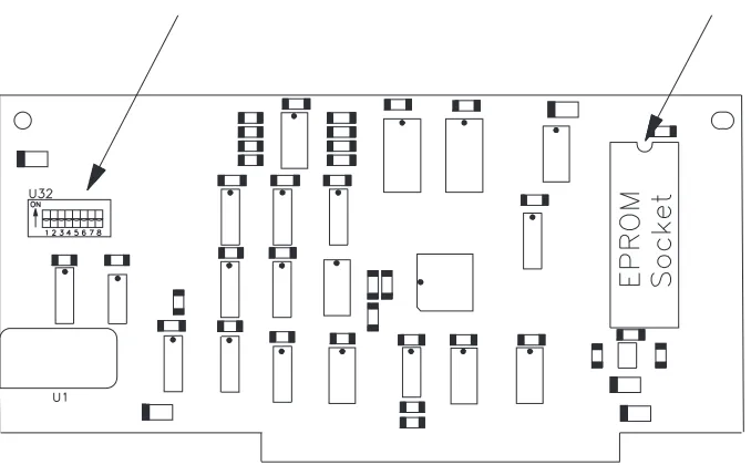
Figure 10-1
10 MX EPROM Removal and Replacement
This section describes how to remove and replace the EPROM on the MX card. Figure 10-1 shows the location of the MX card.
Note: This manual uses the term MX to refer to the MX card and to the MV
and MS cards, which are now obsolete. Refer to Section 8.1 for more information.
10.1 Preparation
The EPROM is socket mounted on the MX card. To access the EPROM, first remove these parts in the following order:
Top cover Section 4
Card retainers Section 6
MX card Section 8
10.2 Identification Information
Before starting this procedure, ensure that you have the correct EPROM for your configuration. The MX (or MS or MV) card uses either a 128 KByte EPROM or a 256 KByte EPROM. In addition, the EPROM you need de-pends on the PCB part number and on the revision level of the code for your configuration. Although this manual does not provide specific information about EPROM part numbers, this section provides general guidelines for de-termining the PCB part number and the card type.
Figure 10-2
[image:54.612.116.455.385.595.2]Location of EPROM for MX, MS, or MV Cards
Figure 10-3
To determine the type of EPROM you need, follow these steps:
1. Determine the card type by looking on the non-component side of the card. Near the top edge of the card are two stickers: one is a serial number sticker and the other is a revision level sticker. The serial number sticker contains the letters MX (or MV or MS), followed by the serial number.
2. Locate the PCB part number. The PCB part number is silk screened on the PCB surface and is located in the lower left-hand corner of the com-ponent side. It is located either in the lower right-hand corner or along the left edge of the non-component side.
3. Refer to Table 10-1 to determine which type of EPROM corresponds to the PCB part number for your type of card.
Type of Card PCB Part No. Type of EPROM
MX 620090-xxxa 128 Kbyte
MX 620091-xxx 256 KByte
MX 620092-xxx 256 KByte
MVb 620080-xxx 128 KByte
MSb 620092-xxx 256 KByte
a
xxx is the revision level for the part number.
b The MV and the MS cards are obsolete.
10.3 EPROM Removal
To remove the EPROM, follow these steps:
1. Place the card on the work surface with the component side up and the card edge connector pointing toward you. Figures 10-2 and 10-3 show the location of the major components on the MX (or MV or MS) card and the location of the EPROM socket.
Table 10-1
MV/MX/MS PCB Part Numbers
Figure 10-4
Location of EPROM for MX, MS, or MV Cards (same as Figure 10-2)
Figure 10-5
[image:56.612.140.481.394.658.2]10.4 EPROM Installation
CAUTION
Be sure to install the correct EPROM on the card. Before installing the EPROM, see Section 10.2 for information about identifying EPROMs and cards correctly.
To install the EPROM if an EPROM insertion tool is available, follow these steps:
1. Select the EPROM to be installed and orient the notch in the EPROM with the notch in the EPROM socket on the card, as shown in either Fig-ure 10-4 or FigFig-ure 10-5.
2. Use the EPROM insertion tool to insert the new EPROM.
To install the EPROM if an EPROM insertion tool is not available, follow these steps:
1. Select the EPROM to be installed and position it on the socket carefully, checking to ensure that each pin on the EPROM is aligned with a hole in the EPROM socket.
2. Place both thumbs on top of the EPROM and press it into the socket. Be careful to provide even pressure on the top of the EPROM so that all pins are inserted at the same time. Uneven pressure can result in the EPROM being only partially inserted and in bent pins on the EPROM.
3. Visually inspect the EPROM to ensure that all of the pins have been cor-rectly inserted. If the EPROM is not fully seated in the socket, apply ad-ditional pressure to bottom out all pins on the EPROM into the socket.
4. If any of the pins are bent, remove the EPROM. Then, attempt to straighten the pins and reinsert the EPROM. Follow the previous steps to remove, insert, and inspect the EPROM.
Figure 10-6
10.5 Reassemble the EXB-8200
To reassemble the EXB-8200, replace these parts in the following order:
MX card Section 8
Card retainers Section 6
Top cover Section 4
Figure 11-1
11 SV Card EPROM Removal and Replacement
This section describes how to remove and replace the EPROM contained on the SV card. There are two different types of SV cards: 721103-Bxx and 721102-Bxx. The steps for replacing the EPROM on SV card 721103-Bxx are described first, followed by the steps for replacing the EPROM on SV card 721102-Bxx.
11.1 Proper Handling of Printed Circuit Cards
When removing or inserting a card, hold the card on the PCB surface. Do not hold the components or connectors mounted on the card. Holding the compo-nents or connectors can damage the card. After removal, hold and place cards on their edges whenever possible.
11.2 Preparation for SV Card 721103-Bxx
The SV EPROM is socket mounted on the SV card. To access the SV card EPROM, first remove these parts in the following order:
Top cover Section 4
Card retainers Section 6
Deck hanger Section 7
DB/DS/DR card Section 8
MX card Section 8
DF card Section 8
CD card Section 8
RW card Section 8
Note: Do not remove SV card 721103-Bxx to replace the EPROM.
11.3 EPROM Removal for SV Card 721103-Bxx
To remove the EPROM, follow these steps:
1. Place the EXB-8200 on the work surface with the front facing you. Lo-cate the EPROM (see Figure 11-1).
2. Remove the EPROM using an appropriate EPROM removal tool.
Figure 11-2
11.4 Preparation for SV Card 721102-Bxx
To access the EPROM on the 721102-Bxx SV card, remove all of the items mentioned in Section 11.2. Then, remove these parts in the following order:
SV card cover Section 4
SV card Section 8
11.5 EPROM Removal for SV Card 721102-Bxx
To remove the EPROM, follow these steps:
1. Place the SV card on the work surface with the component side up and the front edge of the card facing you. The front edge of the SV card is identified by the two LEDs and the circular cutout in the card.
Figure 11-2 shows the location of the major components on the card and the location of the EPROM socket.
2. Using an EPROM removal tool, extract the EPROM from the SV card and set it aside.
11.6 EPROM Installation
To install the EPROM if an EPROM insertion tool is available, follow these steps:
1. Select the EPROM to be installed and orient it with the notch toward the rear edge of the SV card. This will correspond to the notch in the EPROM socket on the SV card.
2. Use the EPROM insertion tool to insert the EPROM.
Figure 11-3
Location of SV Card EPROM for SV Card 721102-Bxx (same as Figure 11-2)
To install the EPROM if an EPROM insertion tool is not available, follow these steps:
1. Carefully position the EPROM on the socket. Check to ensure that each pin on the EPROM is aligned with a hole in the EPROM socket on the SV card.
2. Place both thumbs on top of the EPROM and press it into the socket. Be careful to provide even pressure on the top of the EPROM so that all pins are inserted at the same time. Uneven pressure can result in the EPROM being only partially inserted and in bent pins on the EPROM.
3. Visually inspect the EPROM to ensure that all of the pins have been cor-rectly inserted into the socket. If the EPROM is not fully seated in the socket, apply additional pressure to bottom out all pins into the socket.
4. If any of the pins are bent, remove the EPROM. Then, attempt to straighten the pins and reinsert the EPROM. Follow the previous steps to remove, insert, and inspect the EPROM.
Note: Do not use the EPROM if any of the pins are broken.
11.7 Reassemble the EXB-8200
To reassemble the EXB-8200, replace these parts in the following order:
SV card (for part number 721102-Bxx) Section 9 SV card cover (for part number 721102-Bxx) Section 5
RW card Section 8
CD card Section 8
DF card Section 8
MX card Section 8
DB/DS/DR card Section 8
Deck hanger Section 7
Card retainers Section 6
Top cover Section 4
Figure 12-1
[image:66.612.120.475.368.616.2]Location of Door Release Lever
Figure 12-2
12 Faceplate Removal and Replacement
This section describes how to remove and replace the faceplate.
12.1 Faceplate Removal
To remove the faceplate, follow these steps:
1. To avoid damaging tape, ensure that there is no data cartridge in the EXB-8200.
2. Open the door on the EXB-8200 using an appropriate tool, such as a small screwdriver, to move the door release lever toward the front of the EXB-8200. Figure 12-1 shows the location of the door release lever. The amount of force required to activate the lever is slight and the move-ment is less than 1/8 of an inch. Be careful not to damage the small switch contacts next to the door release lever.
3. Using a T8 TORX screwdriver, loosen the four faceplate mounting screws, but do not completely remove them. Figure 12-2 shows the loca-tion of these screws.
4. Position the EXB-8200 so that it is resting on the rear of the main hous-ing, with the front pointing up and the door open.
5. Move the faceplate away from the main housing. Close the door par-tially, so you can slide the faceplate off of the mounting screws and around the door.
Figure 12-3
Location of Faceplate Mounting Screws (same as Figure 12-2)
12.2 Faceplate Replacement
To replace the faceplate, follow these steps:
1. Position the EXB-8200 on the work surface so that it is resting on the rear of the main housing with the door open and facing up.
2. Close the door partially so that you can slide the faceplate around the door and align it with the four mounting screws (see Figure 12-3).
3. Position the faceplate so that the mounting tabs are under the four mount-ing screws and the faceplate is flush with the door when it is closed.
4. Tighten the mounting screws until they are snug.
CAUTION
Do not overtighten the screws. Overtightening these screws can
damage the faceplate mounting tabs or strip the screw holes in the main housing.
Figure 13-1
Location of Door Release Lever
Figure 13-2
13 Door Removal and Replacement
This section describes how to remove and replace the door.
13.1 Preparation
If necessary, open the door of the EXB-8200 after checking that there is no data cartridge in the EXB-8200. To open the door, use an appropriate tool, such as a small screwdriver, to move the door release lever toward the front of the EXB-8200. Figure 13-1 shows the location of the door release lever. The amount of force required to activate the lever is slight and the movement is less than 1/8 of an inch. Be careful not to damage the small switch contacts next to the door release lever.
13.2 Door Removal
To remove the door, follow these steps:
1. Using a flat blade screwdriver, separate the door from the door retainer. The locking tabs that hold the two together are near the top edge of the door. Figure 13-2 shows where to position the screwdriver to separate the door and the door retainer.
Start with either side of the door and position the screwdriver so that the prying force will separate the two components. Apply the force so that it pushes the door retainer tab toward the outside edge of the door as well as away from the door.
2. Unlatch the remaining locking tab using the same method.
3. Separate the two components so that the bottom locking tabs are also re-leased and both parts can be removed and set aside.
Figure 13-3
13.3 Door Replacement
Practice assembling the door and the door retainer independently of the EXB 8200 several times before attempting to put them on the EXB-8200. Be sure to observe the final relationship of all of the locking tabs so that it is clear how they should look when they are placed on the door mechanism. View A in Figure 13-3 shows how the door, the door retainer, and the door bracket are positioned on the EXB-8200. View B shows a side view of the door, the door bracket, and the door retainer.
To replace the door, follow these steps:
1. If necessary, open the door mechanism on the EXB-8200 after checking that there is no data cartridge in the EXB-8200.
2. Position the door on the arms of the door bracket so that the bottom lock-ing tabs on the door are in the notches on the bottom of the door bracket.
3. Hold the door in position on the door bracket with the thumb and first fin-ger of one hand and position the door retainer so that the locking tab notches on the bottom of the door retainer are by the locking tabs on the door.
4. Squeeze the door and door retainer together using the thumb and first fin-ger of each hand so that the bottom notches snap together with the lock-ing tabs. Apply the pressure so that the door retainer moves in and up under the locking tabs.
5. Squeeze the door and door retainer together at the top edge to engage the top locking tabs.
6. Inspect the door to make sure all tabs are in the correct position. If one of the bottom tabs is not in its correct position, separate the door and the door retainer and restart the replacement procedure.
Figure 14-1
14 Deck Assembly Removal and Replacement
This section describes how to remove and replace the deck assembly.
14.1 Preparation
To replace the deck, first remove these parts in the following order:
Top cover Section 4
Card retainers Section 6
Deck hanger Section 7
Faceplate Section 12
RW card Section 8
CD card Section 8
DF card Section 8
MX card Section 8
DB/DS/DR card Section 8
SV card cover Section 5
SV card Section 9
14.2 Deck Removal
To remove the deck, follow these steps:
1. Remove the four Phillips screws that mount the deck to the main hous-ing, as shown in Figure 14-1.
2. Move the deck out the front of the EXB-8200 and away from the main housing.
Figure 14-2
14.3 Deck Replacement
To replace the deck, follow these steps:
1. Set the new deck in place and start the four mounting screws to hold the deck in place while reassembling the EXB-8200. Do not tighten these screws at this time.
2. Mount the door assembly from the old deck on the new deck (see Sec-tion 13).
3. Install the faceplate on the main housing (see Section 12).
4. Close the door to the deck and position the deck so that the door is flush with the faceplate.
5. Tighten the deck mounting screws to 1.7 inch-pounds of torque.
CAUTION
Do not overtighten the screws. Overtightening these screws can
strip the screw holes in the new deck.
14.4 Reassemble the EXB-8200
To reassemble the EXB-8200, replace these parts in the following order:
SV card Section 9
SV card cover Section 5
DB/DS/DR card Section 8
MX card Section 8
DF card Section 8
CD card Section 8
RW card Section 8
Deck hanger Section 7
Card retainers Section 6
Top cover Section 4
15 Main Housing Removal and Replacement
This section describes how to remove and replace the main housing.
15.1 Preparation
To replace the main housing, first remove these parts in the following order:
Top cover Section 4
Card retainers Section 6
Faceplate Section 12
SV card cover Section 5
Note: You must remove the SV card mounting screws (see Section 9.3), but
the SV card can remain in place. You should also remove the deck mounting screws (see Section 14.2), but there is no need to remove the deck.
15.2 Main Housing Removal
After the main housing has been separated from all other assemblies and com-ponents, the main housing is ready for removal. To remove the main housing, follow these steps:
1. Grasp the main housing by the sides toward the front.
2. Spread the sides of the main housing apart.
3. Push the main housing away from the rest of the EXB-8200 until it is completely separate from the deck and cards, as shown in Figure 15-1.
15.3 Main Housing Replacement
To replace the main housing, follow these steps:
1. Grasp the main housing by the sides at the front.
2. Spread the sides of the main housing apart.
3. Pull the main housing around the deck and cards until it is in place.
4. Inspect the mounting tabs for the SV card cover to ensure that they are positioned so that the SV card and SV card cover can be mounted to the main housing properly. The screws for the SV card cover should go through the SV card cover and SV card before they go into the main housing.
15.4 Reassemble the EXB-8200
To reassemble the EXB-8200, replace these parts in the following order:
Deck assembly Section 14
SV card Section 9
SV card cover Section 5
Card retainers Section 6
Faceplate Section 12
Top cover Section 4
16 Cleaning Procedure
This section describes how to clean an EXB-8200.
16.1 Accepted Procedures and Products
The only cleaning material authorized for use with the EXB-8200 is the EX-ABYTE 8mm Tape Subsystem Cleaning Cartridge 727113 (3 cleanings).
Cloth swabs, cotton swabs, and cleaning agents are not accepted for use and will void the warranty on the EXB-8200.
16.2 Cleaning Intervals
The EXABYTE Cleaning Cartridge is designed as a preventive maintenance product. Use it at regular intervals based on tape drive use. Under normal en-vironmental conditions, use the cleaning cartridge once a month or after ap-proximately 30 gigabytes of data transfer or 30 tape motion hours, whichever occurs first. If the EXB-8200 is experiencing read/write performance prob-lems, perform one or two cleaning passes at that time.
Note: For planning purposes, one gigabyte of data is transferred for every
hour of continuous streaming operation.
16.3 Minimum Firmware Level Required
The EXABYTE Cleaning Cartridge will work properly with all EXB-8200s that have MX processor firmware of at least 4$22 and SV processor firmware of at least B016. Inserting a cleaning tape into EXB-8200s below these firm-ware levels causes the EXB-8200 to identify the cleaning tape as a data tape. If this occurs, the EXB-8200 will load the cleaning tape and show Ready status (green LED lit). Press the unload button to unload the cleaning car-tridge.
16.4 Cleaning Action Performed by Cartridge
When a cleaning cartridge is inserted into an EXB-8200 with the proper firm-ware levels, the cleaning tape is loaded into the tape path and moved forward for approximately 15 seconds. At the end of this time, the cleaning tape is drawn back into the cartridge and the cartridge is ejected. The EXB-8200 is ready for use at this point.
16.5 Usage and Reusage
The EXB-8200 8mm Tape Subsystem Cleaning Cartridge is designed for three uses and then disposal. The cleaning tape should never be rewound or reused since the chances of reintroducing contaminants are very high. Firm-ware 4$22 and above are designed to prevent the EXB-8200 from rewinding cleaning tapes.
16.6 Cleaning Instructions
To clean an EXB-8200, follow these steps:
1. Apply power to the EXB-8200. When the power-on cycle is complete, open the door and remove any data cartridge from the EXB-8200. Leave the door open.
2. Place the cleaning cartridge into the EXB-8200 and close the door.
The remainder of the cleaning process is automatically performed by the EXB-8200. When the cleaning process is complete, the cleaning car-tridge is automatically unloaded and ejected from the EXB-8200. The average cleaning cycle is 15 seconds.
3. Record the date on the cartridge label.
4. Store the cleaning cartridge for future use.
Note: To prevent contamination of the EXB-8200, do not rewind the
17 Tape Removal Procedure
This section describes how to remove a data cartridge that is loaded in the tape path around the rotating head assembly of a nonfunctioning EXB-8200. Use this procedure only as a last option when it is necessary to preserve the data on the tape.
Before using this procedure and if there are any questions about this proce-dure, contact EXABYTE Technical Support. Technical Support will attempt to provide alternate methods for recovering the data cartridge.
IMPORTANT
EXABYTE Corporation does not assume responsibility for any dam-age to the EXB-8200, the data cartridge, or media or for the loss of any data resulting from this procedure. Any damage to the
EXB-8200 caused by this procedure will be repaired as a nonwarranty repair and may void the existing warranty for the EXB-8200.
17.1 Preparation
Before attempting this procedure, remove and reapply power to the EXB-8200 in an attempt to clear a possible hang condition. If the green LED is lit, indicating Ready status, push the unload button or issue a SCSI UNLOAD command. If the green LED is not lit, continue with the instructions in this section.
17.2 Definitions
Non-functioning EXB-8200. For the purposes of this procedure, a
non-func-tioning EXB-8200 is an EXB-8200 that fails to execute the rewind/unload op-eration on power up.
Rewind/Unload Operation. The rewind/unload operation is the operation in
Figure 17-1
17.3 Required Tools
The following tools are required:
3/8-inch straight blade screwdriver Pointed tweezers
#0 Phillips screwdriver T8 TORX screwdriver T10 TORX screwdriver
Torque measuring screwdriver (1.0 to 5.0 inch-pounds) Adhesive tape
Nonconductive tool, such as a molded potentiometer adjustment tool.
17.4 Disconnect the EXB-8200
Following all procedures appropriate to the system in which the EXB-8200 is installed, disconnect the EXB-8200 from the power supply and the SCSI bus. Remove the EXB-8200 from the system and transport it to the work area.
17.5 Preparation of the EXB-8200
Remove the top cover, as described in Section 4.
17.6 Cartridge Preparation
To prevent possible damage to the tape by the data cartridge door during this procedure, the door must be taped open. Taping the door open prevents the cartridge door from closing on the tape and damaging it before the tape is re-wound into the data cartridge. Figure 17-1 shows a data cartridge with the door taped open.
To tape the door open, follow these steps:
1. Obtain two pieces of adhesive tape, each approximately two inches long.
2. Position the two pieces of tape as shown in Figure 17-1, and press them gently to the data cartridge.
Figure 17-2
17.7 Erase Head Bracket Removal
The erase head bracket is a molded black plastic part, as shown in Figure 17-2. It is mounted onto two posts. The erase head is attached to the bracket where the wires emerge and lead to the connector on the SV card.
To remove the erase head bracket, follow these steps:
1. Remove the small Phillips head screw that holds the erase head bracket in place (see Figure 17-2).
Note: Early models of the EXB-8200 do not have the mounting screw. In
EXB-8200s without the mounting screw, go to step 2.
2. Lift the erase head bracket straight up at the base. The connector and wires do not have to be removed from the SV card since there is suffi-cient slack in the connector wires to allow the erase head bracket to be re-moved.
3. Position the erase head bracket so that it is hanging over the side of the EXB-8200 and away from the tape path.
17.8 Tape Guide Removal
The tape guide is a molded black plastic part, as shown in Figure 17-2. It looks like the boom on a crane and is mounted on three posts as shown. The largest post is the primary mounting post, and the other two posts are guides for correct positioning of the tape guide.
To remove the tape guide, follow these steps:
1. Gently lift the tape guide straight up at the primary mounting post, so that it is removed from all three posts at the same time.
2. Set the tape guide aside, so it can be replaced later.
Figure 17-3
EXB-8200 with Tape Loaded