warwick.ac.uk/lib-publications
Manuscript version: Author’s Accepted Manuscript
The version presented in WRAP is the author’s accepted manuscript and may differ from the
published version or Version of Record.
Persistent WRAP URL:
http://wrap.warwick.ac.uk/129553
How to cite:
Please refer to published version for the most recent bibliographic citation information.
If a published version is known of, the repository item page linked to above, will contain
details on accessing it.
Copyright and reuse:
The Warwick Research Archive Portal (WRAP) makes this work by researchers of the
University of Warwick available open access under the following conditions.
Copyright © and all moral rights to the version of the paper presented here belong to the
individual author(s) and/or other copyright owners. To the extent reasonable and
practicable the material made available in WRAP has been checked for eligibility before
being made available.
Copies of full items can be used for personal research or study, educational, or not-for-profit
purposes without prior permission or charge. Provided that the authors, title and full
bibliographic details are credited, a hyperlink and/or URL is given for the original metadata
page and the content is not changed in any way.
Publisher’s statement:
Please refer to the repository item page, publisher’s statement section, for further
information.
Uplink Precoding Optimization for NOMA Cellular-Connected
UAV Networks
Xiaowei Pang, Guan Gui,
Senior Member, IEEE
, Nan Zhao,
Senior Member, IEEE
, Weile Zhang,
Yunfei Chen,
Senior Member, IEEE,
Zhiguo Ding,
Senior Member, IEEE,
and Fumiyuki Adachi,
Life
Fellow, IEEE
Abstract—Unmanned aerial vehicles (UAVs) are playing an important role in wireless networks, due to their cost effectiveness and flexible deployment. Particularly, integrating UAVs into existing cellular networks has great potential to provide high-rate and ultra-reliable communications. In this paper, we investigate the uplink transmission in a cellular network from a UAV using non-orthogonal multiple access (NOMA) and from ground users to base stations (BSs). Specifically, we aim to maximize the sum rate of uplink from UAV to BSs in a specific band as well as from the UAV’s co-channel users to their associated BSs via optimizing the precoding vectors at the multi-antenna UAV. To mitigate the interference, we apply successive interference cancellation (SIC) not only to the UAV-connected BSs, but also to the BSs associated with ground users in the same band. The precoding optimization problem with constraints on the SIC decoding and the transmission rate requirements is formulated, which is non-convex. Thus, we introduce auxiliary variables and apply approximations based on the first-order Taylor expansion to convert it into a second-order cone programming. Accordingly, an iterative algorithm is designed to obtain the solution to the problem with low complexity. Numerical results are presented to demonstrate the effectiveness of our proposed scheme.
Index Terms—Non-orthogonal multiple access, precoding op-timization, successive interference cancellation, unmanned aerial vehicle.
Manuscript received April 22, 2019; revised August 16, 2019 and October 28, 2019; accepted November 12, 2019. The work of N. Zhao was supported by the National Natural Science Foundation of China (NSFC) under Grant 61871065, the open research fund of State Key Laboratory of Integrated Services Networks under Grant ISN19-02. The work of Z. Ding was supported by the UK EPSRC under grant number EP/P009719/2 and by H2020-MSCA-RISE-2015 under grant number 690750. Part of this work has been published in preliminary form in the Proceedings of IEEE PIMRC 2019 [1]. The associate editor coordinating the review of this paper and approving it for publication was F. Verde.(Corresponding author: Nan Zhao.)
N. Zhao and X. Pang are with the School of Information and Com-munication Engineering, Dalian University of Technology, Dalian 116024, P. R. China, and also with the State Key Laboratory of Integrated Ser-vices Networks, Xidian University, Xi’an, 710071, P. R. China (email: [email protected], [email protected]).
G. Gui is with the College of Telecommunications and Information En-gineering, Nanjing University of Posts and Telecommunications, Nanjing 210028, Jiangsu, China (e-mail: [email protected]).
W. Zhang is with the School of Electronic and Information Engineer-ing, Xi’an Jiaotong University, Xi’an, Shaanxi, 710049, China (e-mail: [email protected]).
Y. Chen is with the School of Engineering, University of Warwick, Coventry CV4 7AL, U.K. (e-mail: [email protected]).
Z. Ding is with the School of Electrical and Electronic Engineer-ing, the University of Manchester, Manchester M13 9PL,, U.K. (e-mail: [email protected]).
F. Adachi is with the Research Organization of Electrical Communication, Tohoku University, Sendai 980-8577, Japan (e-mail: [email protected]).
I. INTRODUCTION
Recently, unmanned aerial vehicles (UAVs) have been wide-ly utilized for multifarious scenarios, such as cargo delivery, surveillance and monitoring, remote sensing, communication platforms [2], [3], due to their high mobility and cost-effectiveness. Compared to terrestrial wireless networks, UAV-assisted networks can be deployed more swiftly, reconfigured more flexibly, and have a much higher chance of line-of-sight (LoS) in air-to-ground wireless links [4], which are useful to provide high-speed and on-demand wireless connectivity for wireless communication systems. There exists extensive research on UAV channel modeling and measurement in various operational environments [5], which has revealed the significant impact of the placement of UAV and its surrounding environments on UAV communication performance.
Due to these benefits, UAVs have been typically employed as aerial base stations (BSs) [6] or mobile relays [7] to assist terrestrial wireless networks and enhance the quality of service (QoS) for ground users. Specifically, the UAVs are deployed as aerial BSs to provide seamless wireless coverage within the service area in which the terrestrial infrastructure does not function [8] or to offload data traffic for ground BSs in hotspots [9]. Furthermore, exploiting the controllable mobility of UAVs, the trajectory of UAV can be properly designed to serve ground users more efficiently. Motivated by this, Wuet al. jointly optimized the user scheduling, UAV trajectory and power control in a multi-UAV enabled wireless network in [10] and maximized the minimum throughput among ground users. In [11], Caiet al.proposed an effective scheme to jointly opti-mize the trajectory and user scheduling to guarantee the secure transmission in a dual-UAV enabled wireless network. UAV-enabled networks with energy consumption consideration were studied in [12], where the trajectory was designed to maximize the energy efficiency of UAV. Moreover, the UAV-assisted communication can also be integrated with other promising technologies, such as millimeter-wave communications [13], [14] and proactive caching techniques [15], [16].
with the rate performance of UAV communication [17], and the feasibility of serving UAVs by leveraging the cellular infrastructure was studied in [18]. Despite the promising advantages, one of the challenging issues for the efficient realization of cellular-connected UAV is that the dominance of LoS aerial-ground links may cause severe interference to the other BSs in uplink [19]. Investigations on aerial interference mitigation have been conducted by Amorim et al. in [20], which demonstrated the performance of existing interference mitigation techniques for cellular-connected UAVs. In [21], Meiet al.proposed the optimal inter-cell interference coordi-nation design for cellular-connected UAV networks via jointly optimizing the UAV association and power allocation (PA). Considering the mobility of UAV, the trajectory of a cellular-connected UAV was optimized by Zhang et al. to minimize the UAV’s mission completion time in [22].
On the other hand, non-orthogonal multiple access (NOMA) has received significant attention from both academia and industry due to its superior spectral efficiency [23], [24]. In NOMA schemes, successive interference cancellation (SIC) is applied at receivers to cancel the multi-user interference with PA at transmitters. Considering the application of multiple-input multiple-output to NOMA systems, Dinget al.proposed a novel design of precoding and detection matrices and ana-lyzed its performance in [25]. NOMA can also be exploited in UAV enabled wireless networks. Liu et al. proposed a fundamental framework for the NOMA UAV networks with massive connections in [26]. In [27], Zhao et al. jointly optimized the UAV trajectory and precoding vectors at the BS using NOMA to maximize the sum rate in UAV-assisted NOMA cellular networks. The joint optimization of placement and PA for NOMA based UAV networks was studied by Liu
et al. in [28]. Focusing on cellular-connected UAV networks, a novel cooperative NOMA scheme was proposed by Mei and Zhang in [29] by utilizing existing backhauls among BSs to realize interference cancellation, where the weighted sum rate of UAV and ground users is maximized by jointly optimizing the UAV’s rate and PA over multiple resource blocks.
Motivated by the above research, in this paper, we focus on studying a cellular network with a multi-antenna UAV as the aerial user and some ground users served by BSs, where the special emphasis is placed on the uplink data transmission from the UAV and from the ground users to their corresponding BSs. Owning to the scarce spectrum and the superiority of NOMA [23], [24], we adopt NOMA for the UAV transmission sharing a specific frequency band with the existing ground users. Different from [30], we intend to maximize the sum rate of UAV and its co-channel users by optimizing the precoding vectors. To mitigate the interference generated by UAV to ground users in the uplink transmission, we directly adopt SIC at the co-channel BSs corresponding to the ground users in the same band, without employing backhauls among BSs as conducted in [29], [30].
The main contributions of this paper are summarized as follows.
• In this paper, we propose a cellular-connected UAV wireless network where the multiple-antenna UAV co-existing with ground users communicates with ground
BSs. Particularly, we investigate the uplink transmission herein, including the payload data transmission of UAV to BSs with high-rate requirements and the information transmission from ground users to BSs.
• To improve the spectral efficiency, NOMA is employed on the transmission of UAV, sharing the spectrum with a number of existing ground users. To mitigate the strong interference generated by the UAV to ground users in uplink, SIC is not only applied to the UAV-connected BSs, but also to the BSs associated with the UAV’s co-channel users. As a result, the interference can be suppressed by precoding optimization at UAV as well as leveraging SIC at the co-channel BSs.
• We aim to maximize the uplink sum rate of UAV and its co-channel users in the same band via precoding optimization at the UAV. Since the problem is non-convex and difficult to tackle, we use a series of approximations based on the first-order Taylor expansions to render it into a convex one. Then, a sub-optimal solution can be ob-tained via an iterative algorithm with low computational complexity.
The rest of this paper is organized as follows. In Section II, the system model is introduced, and the precoding optimiza-tion problem is formulated in Secoptimiza-tion III. To obtain the optimal precoding vectors, the non-convex problem is transformed into a convex one and solved by an iterative algorithm in Section IV. In Section V, simulation results are provided, followed by the conclusions in Section VI.
Notation:For a vectora, its Euclidean norm is denoted by ∥a∥, and aH represents its conjugate transpose.CM×N is the
space of M×N complex matrices. CN(a,A)represents the complex Gaussian distribution with meanaand covarianceA. Re(c)is the real part of a complex numberc.
II. SYSTEMMODEL
Consider a cellular network where a UAV at a fixed altitude Hu co-existing with a number of ground users is served by
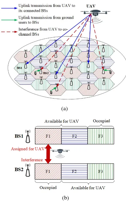
the ground BSs to guarantee safe and reliable operation. In turn, the UAV sends back the telemetry report, pictures and videos to BSs with high data rate in the uplink transmission1. As shown in Fig. 1(a), we investigate the uplink transmission from the UAV to its connected BSs in a specific frequency band and from the UAV’s co-channel ground users to their corresponding BSs. Specifically, we employ the frequency reuse scheme with a factor of 32, which can be referred to Fig. 3(b) in [31]. In the proposed scheme, adjacent cells are allocated with three different frequency bands, which are denoted by F1, F2 and F3, respectively. Furthermore, we take BS1 and BS2 for example to illustrate the frequency allocation in the uplink transmission, as shown in Fig. 1(b). To avoid co-channel interference, the UAV is supposed to communicate with its connected BSs in a specific band that is not occupied
1Although the UAV sends different messages to different BSs, we deem it
as an aerial user to avoid ambiguity and be consistent with the existing works [17], [18]. This is reasonable because each BS can decode its desired message and then forwards it to its serving ground users to satisfy their demands.
2The proposed scheme can be easily extended to adopt other frequency
(a)
[image:4.612.60.280.57.407.2](b)
Fig. 1. Schematic diagram for the NOMA cellular-connected UAV network. (a) Uplink transmission of UAV and co-channel users in the cellular network. (b) An example of the spectrum utilization.
by any ground users. For the UAV-connected BS1, F3 is occupied by ground users, and F1 and F2 are available for the UAV. Thus, we assign F1 for UAV transmission. As a result, interference will appear between the UAV and the uplink transmission of the co-channel users in BS2 in F1.
Assume that there are I BSs in total, the set of which is denoted by I. Define the set of BSs serving ground users in frequency bandn asI(n), which satisfies
I(n)⊆ I,{1,2, . . . , i, . . . , I}. (1)
Then, according to the frequency reuse, the set of other BSs with the frequency bands for ground users that are orthogonal to band ncan be expressed as
Ic(n) =I \ I(n). (2)
For more general cases, suppose that the UAV adopts NOMA for its uplink transmission to J BSs in the assigned bandn, which are not occupied by any users at the same cells. Thus, the set of the J UAV-connected BSs can be denoted by
J ,{1,2, . . . , j, . . . , J} ⊆ Ic(n). (3)
Since the UAV and a number of ground users perform transmission simultaneously in the same band, the severe
co-channel interference should be well managed. It is worth noting that the interference from the ground users to the UAV-connected BSs is much weaker than that from the UAV to the corresponding BSs of ground users, due to the more severe path-loss and shadowing of the terrestrial transmission. Thus, the interference caused by the UAV should be carefully controlled. Assume that the UAV is equipped withM antennas while each ground user has a single antenna. Since the anten-nas of BSs are generally tilted downwards for serving ground users, the aerial users can only be served by the sidelobes [29]. Thus, for simplicity, each BS can be equivalently regarded as being equipped with a single antenna due to its fixed beam pattern for the UAV. The Rician channel fading model is adopted for the channel from the UAV to BS i, i ∈ I, with the channel vector denoted by
hi=
√ ρ
0
dui2+Hub2
(√
K K+1bhL+
√
1
K+1bhR
)
, ∀i∈ I, (4)
whereρ0 represents the channel power gain at the reference
distanced0= 1m anddui is the horizontal distance between
the UAV and BS i. Hub denotes the vertical distance from
the UAV to the BSs with an identical heightHb, which yields
Hub =Hu−Hb.bhL∈C1×M is the LoS channel component
with∥bhL∥= 1 andbhR∈C1×M follows the Rayleigh fading
which holds bhR ∼ CN(0,I). K ≥ 0 refers to the Rician
factor corresponding to the ratio between the LoS power and Rayleigh fading components.
In the considered cellular network, the active co-channel users that are communicating with BSs in I(n) in band n are denoted by w ∈ W , {1,2, . . . , W}. As for the uplink channel from a ground userwto its serving BS, we consider that the channel fading model consists of a distance-dependent path-loss component and a small-scale fading. Therefore, the channel power gain is expressed as
Gw=
α0 (H2
b +d2w)λ/2
gw, ∀w∈ W, (5)
wheredw denotes the the horizontal distance between the
co-channel userwand its serving BS. The height of ground users can be ignored.α0is the channel power gain at the reference
distance d0 = 1 m, λ denotes the path-loss exponent with
λ > 2, and gw ∼ E(1) is an exponential random variable
with unit mean accounting for the small-scale Rayleigh fading channel gain from userwto its serving BS.
III. PRECODINGOPTIMIZATION
In this section, we optimize the precoding for the cellular-connected UAV to maximize the uplink rate of UAV and its co-channel users, while mitigating the interference caused by the UAV to the uplink transmission of ground users.
A. SIC Constraints and Rate Expressions
Motivated by this, we assume that the BSs associated with co-channel users in band ncan also employ SIC to decode part of the strong signals from UAV. As a result, these BSs can completely or partially cancel the interference from the UAV before decoding the uplink signals from co-channel users, and thus the rate requirements of these users can be guaranteed.
Without loss of generality, we use the norms of channel vectors to denote the channel strengths and assume that the channel conditions from the UAV to its connected BSs follow
∥h1∥ 2
≤∥h2∥ 2
≤. . .≤∥hj∥ 2
≤. . .≤∥hJ∥ 2
. (6)
Without loss of generality, the decoding order of these BSs is increasing with their channel strengths according to NOMA and thereby is in accordance with their index numbers. As-suming that by performing SIC, the jth BS can successfully decode the signals transmitted from UAV to the BSs from 1st to(j−1)th before recovering its own message. As a result, the signal-to-interference-plus-noise ratio (SINR) at thejth BS to decode its own message can be expressed as
SINRjj= |hjvj| 2
J
∑
k=j+1
|hjvk| 2
+ W
∑
w=1
PwG j
w+σ2j
, j= 1, ..., J−1,(7)
where vj ∈ CM×1 represents the complex precoding vector
for the signal from UAV to the jth BS, with ∥vj∥ 2
= pj,
j ∈ J, Pw is the transmit power of user w and σj2 is the
power of the additive white Gaussian noise (AWGN) at BSj. Gj
w is the channel power gain from the co-channel userwto
BS j which also follows the model in (5). Particularly, when j =J, the SINR can be calculated as
SINRJJ=
|hJvJ| 2
W
∑
w=1
PwGJw+σJ2
. (8)
To guarantee that BSmcan successfully decode the signal of BS j to perform SIC,m≥j, it is necessary to satisfy
SINRjm= |hmvj| 2
J
∑
k=j+1
|hmvk| 2
+ W
∑
w=1
PwGmw+σm2
≥rj, m≥j, (9)
whererj denotes the SINR threshold for the transmission rate
from UAV to its connected BSj.
To allocate more resource to the weaker BSs with poorer channel strengths to boost up the SINR needed to decode their messages, we have the constraint as
|hjv1|2≥ |hjv2|2≥. . .≥ |hjvJ|2, ∀j∈ J, (10)
which guarantees the decoding order for UAV connected BSs. For convenience, we usehwto represent the channel vector
from the UAV to the BS associated with ground userw(w∈ W)following the model in (4). With applying SIC at the user-connected BSs considered, we define the set of ground users transmitting in bandnwhose associated BS can perform SIC to eliminate the interference of UAV’s jth signal as
f
Wj ,
{
w:∥hw∥ 2
≥max
{
aPwGw ˆ
pj
,∥hj∥ 2
}
, w∈W
}
,(11)
where pˆj is the estimated value of the power ∥vj∥ 2
= pj
allocated for the transmission from UAV to BS j, andais a constant. The inequality in (11) can be equivalently rewritten as the following two sub-inequations.
∥hw∥2≥aPwGw/pˆj, (12)
∥hw∥ 2
≥∥hj∥ 2
. (13)
The inequality (12) can be further changed into
ˆ
pj∥hw∥ 2
≥aPwGw, (14)
which aims to make a comparison between the strength of the interference from UAV and the desired signal from the ground user at the specific BS, with a coefficient a ≥ 1 according to the approximate representation of the interference strength by pˆj∥hw∥
2
. This constraint supports that the interference of UAV’s jth signal should be canceled in the case that the power of interference is much stronger than that of the desired signal from the ground user w at its BS. Moreover, the inequality in (13) indicates that only when the co-channel BSs own better channels with UAV than that between the UAV and its connected BS j, the interference can be decoded and eliminated by employing SIC.
However, the PA for UAV’s transmission is not predefined before the precoding optimization. To this end, we use a rough
ˆ
pj by applying the classic water-filling method as the transmit
power from UAV to its connected BSj in (11) as
ˆ
pj =
(
1
λln 2−
σ2 j
∥hj∥ 2
)+
, ∀j∈ J, (15)
wherex+= max(x,0)andλis a parameter satisfying
J
∑
j=1
(
1
λln 2−
σ2j ∥hj∥2
)+
=Pmu, (16)
wherePmu refers to the maximum transmit power of UAV.
For each ground user w ∈ W, we define a set Jew ,
{1,2, . . . , Jw}, where j ∈ Jew if the signal from the UAV
for BS j can be decoded at the BS associated with user w, i.e., w ∈ Wfj. If no signal of UAV can be decoded for the
BS associated with userw, we have Jew=∅ andJw= 0. To
perform SIC at the BSs inI(n), the following constraint on the SINR of the UAV’s signal for BS j at the associated BS of userwwith1≤j≤Jwshould be satisfied:
SINRjg,w=
|hwvj| 2
J
∑
k=j+1
|hwvk| 2
+PwGw+σw2
≥rj, w∈Wfj,(17)
whereσ2wis the AWGN power at the BS associated with user w. Particularly, ifj=Jw=J, the corresponding SINR satisfies
SINRJg,w=
|hwvJ| 2
PwGw+σ2w
≥rJ, w∈WfJ. (18)
perform SIC successfully.
|hwv1|2≥ |hwv2|2≥. . .≥ |hwvJw|
2≥P
wGw, Jew̸=∅.(19)
After SIC, the SINR for the co-channel userwat its associated BS to decode its own message can be expressed as
SINRwg,w = PwGw J
∑
k=Jw+1
|hwvk|2+σ2w
, Jw< J. (20)
Particularly, ifJw=J, the SINR can be calculated as
SINRwg,w=PwGw/σ2w. (21)
Accordingly, the UAV’s achievable rate for the target BS j ∈ J can be obtained as
Rju
= log2
(
1+min
{
SINRjj, . . . ,SINRjJ,min
w∈Wfj
{
SINRjg,w}
})
,(22)
which aims to ensure that the signal of UAV for BSjcan also be decoded successfully at other UAV-connected BSs as well as the co-channel BSs associated with users w∈Wfj.
As for userw, the achievable rate at its associated BS can be expressed as
Rwg= log2(1+SINRwg,w), w= 1,2, ..., W. (23) The SINR expressions in (20) and (21) indicate that the interference from UAV to the BSs associated with co-channel users can be eliminated partially via SIC, and thus, their transmission rates can be improved according to (23).
B. Problem Formulation
In this paper, our objective is to maximize the uplink sum rate of the UAV and its co-channel ground users by optimizing the UAV’s precoding vectors as
max
vj J
∑
j=1
Ruj+ W
∑
w=1
Rwg. (24)
It is worth pointing out that the expression (21) reveals that the transmission rate of a specific ground user is irrelevant to the UAV precoding vectors if all signals from UAV can be eliminated via SIC at its associated BS. Thus, we exclude these interference-free users and define a new set to denote the ground users that still suffer the interference from UAV as W′ , {1,2, . . . , w, . . . , W′} ⊆ W. Then, the objective function (24) can be equivalently expressed as
max
vj J
∑
j=1
Ruj+
W′
∑
w=1
Rwg. (25)
With aforementioned objective function and constraints, the
joint precoding optimization problem can be formulated as
max
vj J
∑
j=1
Rju+
W′
∑
w=1
Rwg (26a)
s.t. Rju≥η, j= 1,2, ..., J, (26b)
Rwg ≥β, w= 1,2, ..., W′, (26c)
|hjv1|2≥ |hjv2|2≥. . .≥ |hjvJ|2, ∀j∈ J, (26d)
|hwv1|2≥. . .≥ |hwvJw|
2≥P
wGw, Jew̸=∅, (26e) J
∑
j=1
∥vj∥2≤Pmu, (26f)
where (26b) and (26c) are intended to guarantee the uplink transmission rate of the UAV and co-channel users according to the rate thresholds η and β, respectively. The constraint (26f) demands that the total power of UAV transmission is not higher than the maximum value Pmu. In addition,
NO-MA decoding condition constraints (26d) and (26e) are also considered. As can be observed, this problem is intractable due to the fact that the objective function and the constraints except (26f) are all non-convex. Therefore, it is necessary to transform this problem into a convex one whose solution can be computationally efficiently found.
IV. PROPOSEDSOLUTION TO(26)
In this section, a series of approximations are conducted to transform (26) into a convex one, and then, an iterative algorithm is proposed to solve it. In addition, the placement of the UAV is also discussed.
A. Approximate transformations
To make (26) solvable, we first introduce a set of auxiliary variablestq, q= 1,2, . . . , J+W′, to replace the rate in the
objective function and constraints, and we have
max
vj,tq
log2(t1t2. . . tJtJ+1. . . tJ+W′) (27a)
s.t. 1+minm≥j
{
SINRjm
}
≥tj, j= 1, ..., J−1, (27b)
1+SINRJJ≥tJ, (27c)
1+minw∈Wf
j{SINR j
g,w} ≥tj, j= 1, . . . , J, (27d) 1+SINRwg,w≥tJ+w, w= 1, . . . , W′, (27e)
tj ≥2η, ∀j∈ J, (27f)
tJ+w≥2β, ∀w∈ W′, (27g)
|hjv1|2≥ |hjv2|2≥. . .≥ |hjvJ|2, ∀j∈ J, (27h)
|hwv1|2≥. . .≥ |hwvJw|
2≥P
wGw, Jew̸=∅, (27i) J
∑
j=1
∥vj∥2≤Pmu. (27j)
mean among tq as
max
vj,tq
J+W ′ ∏ q=1 tq 1
J+W′
, (28)
which can be transformed into second-order cone (SOC) constraints in the subsequent operations. In addition, (27b)-(27e) can be rewritten using the derived SINR expressions in (7)-(9), (17), (18) and (20) as
s.t.
1+ |hmvj| 2
J
∑
k=j+1
|hmvk|2+ W
∑
w=1
PwGmw+σ2j
≥tj, m≥j,
1+ |hwvj| 2
J
∑
k=j+1
|hwvk| 2
+PwGw+σw2
≥tj, w∈Wfj,
j= 1,2, ..., J−1, (29a)
1 + |hJvJ| 2
W
∑
w=1
PwGJw+σJ2
≥tJ, (29b)
1 + |hwvJ| 2
PwGw+σw2
≥tJ, w∈WfJ, (29c)
1 + PwGw
J
∑
k=Jw+1
|hwvk|2+σw2
≥tJ+w, w= 1, ..., W′. (29d)
Thus, the optimization problem (27) can be further recast as
max
vj,tq
J+W ′ ∏ q=1 tq 1
J+W′
(30a) s.t. J ∑ k=j+1
|hmvk| 2
+ W
∑
w=1
PwGmw+σ2j ≤
|hmvj| 2
tj−1
, m≥j,
J
∑
k=j+1
|hwvk| 2
+PwGw+σw2 ≤
|hwvj| 2
tj−1
, w∈Wfj,
j= 1,2, ..., J−1, (30b)
W
∑
w=1
PwGJw+σ 2
J≤
|hJvJ|2
tJ−1
, (30c)
PwGw+σw2 ≤
|hwvJ| 2
tJ−1
, w∈WfJ, (30d)
J
∑
k=Jw+1
|hwvk|2+σw2 ≤
PwGw
tJ+w−1
, w= 1, ..., W′, (30e)
tj ≥2η, ∀j∈ J, (30f)
tJ+w≥2β, ∀w∈ W′, (30g)
|hjv1|2≥ |hjv2|2≥. . .≥ |hjvJ|2, ∀j ∈ J, (30h)
|hwv1|2≥. . .≥ |hwvJw|
2≥P
wGw, Jw≥1, (30i) J
∑
j=1
∥vj∥2≤Pmu, (30j)
which is still non-convex and cannot be solved directly. To this end, we use approximations for the non-convex constraints
(30b)-(30e) according to Proposition 1 to make them convex.
Proposition 1:The constraints (30b)-(30e) can be
approx-imately transformed into the following convex ones.
s.t. J ∑ k=j+1
|hmvk| 2
+ W
∑
w=1
PwGmw+σ2j ≤ Tm,j, m≥j,
J
∑
k=j+1
|hwvk| 2
+PwGw+σ2w≤ Tw,j, w∈Wfj,
j= 1,2, ..., J−1, (31a)
W
∑
w=1
PwGJw+σ 2
J ≤ TJ,J, (31b)
PwGw+σ2w≤ Tw,J, w∈WfJ, (31c) J
∑
k=Jw+1
|hwvk|2+σw2 ≤ Sw, w= 1, ..., W′, (31d)
where
Tm,j,Tm,j
(
hm,vj, tj,vrj, t r j
)
= 2Re
(
hmvrjvHj h H m
)
tr
j−1
−hmv
r
jvrHj h
H m
(
tr
j−1
)2 (tj−1), (32)
and
Sw,Sw
(
tJ+w, trJ+w
)
= ( PwGw
tr
J+w−1
)2
(
2trJ+w−tJ+w−1
)
. (33)
Proof:For convenience, we first define
Fm,j(hm,vj, tj) = | hmvj|2
tj−1
, (34)
Fw(tJ+w) =
PwGw
tJ+w−1
, (35)
where tj > 1, tJ+w > 1 and hHmhm ≽ 0. We can observe
that (34) is a convex quadratic-over-linear function, and the function in (35) is also convex with respect to tJ+w. Recall
that for any convex function, it is globally lower-bounded by its first-order Taylor expansion at a feasible point. Due to that (34) is convex with respect tovj ortj, it can be approximated
by the corresponding first-order Taylor expansion at the given local point as a lower bound, which can be derived as
Fm,j(hm,vj, tj)≥Fm,j
(
hm,vrj, t r j ) + 2Re { ∂Fm,j (
hm,vrj,trj
)
∂vrj
(
vj−vrj
)}
+∂Fm,j(hm,vj,tj)
∂tr j
(
tj−trj
)
,Tm,j
(
hm,vj, tj,vrj, t r j
)
, (36)
where(vr
j, trj)is a given feasible point of (30). Similarly, the
first-order approximation of (35) at a given pointtr
J+wcan be
expressed as
Fw(tJ+w)≥
PwGw
tr
J+w−1
− PwGw
(
tr
J+w−1
)2
(
tJ+w−trJ+w
)
,Sw
(
tJ+w, trJ+w
)
. (37)
(30b)-(30e) with their corresponding first-order Taylor approx-imations, respectively. As a consequence, these non-convex constraints can be converted into convex ones as in (31).
In order to handle the non-convex constraints (30h) and (30i), we can replace the quadratic terms with their first-order Taylor approximations following the similar procedure in Proposition 1. Specifically, the following function
Ym,j(hm,vj) =|hmvj|2, (38)
is convex, and thus its first-order Taylor series can serve as a lower bound. With a given point vr
j, we have
Ym,j(hm,vj)≥Ym,j(hm,vrj)+2Re
{
∂Ym,j(hm,vj)
∂vr j
(vj−vrj)
}
,Qm,j
(
hm,vj,vrj
)
, (39)
where
Qm,j
(
hm,vj,vrj
)
= 2Re(hmvjvrHj h H m
)
−hmvrjv rH
j h
H
m. (40)
For the ease of exposition, we define a new set of expres-sions to denote the SIC constraint (30h) for each BSj, which can be given as
Fj=
|hjvJ|2≤min
{
|hjvJ−1|2, . . . ,|hjv1|2
}
, |hjvJ−1|2≤min
{
|hjvJ−2|2, . . . ,|hjv1|2
}
, . . . ,
|hjv2|2≤ |hjv1|2,
(41)
where the quadratic term on the right side of these inequalities can be replaced by their corresponding first-order Taylor approximations, and then the decoding constraints can be approximately transformed as the following convex ones.
e
Fj =
|hjvJ|2≤ min
m∈[1,J−1]{Qj,m(hj,vm,v
r
m)},
|hjvJ−1|2≤ min
m∈[1,J−2]{Qj,m(hj,vm,v
r
m)},
. . . ,
|hjv2|2≤ Qj,1(hj,v1,vr1).
(42) Similarly, we adopt the approximations on the constraint (30i) to make it more tractable. Specifically, the decoding channel condition for user wcan be rewritten as
Fw=
PwGw≤ |hwvJw|
2,
|hwvJw|
2≤min{|h
wvJw−1|
2, . . . ,|h
wv1|2
}
, . . . ,
|hwv2|2≤ |hwv1|2.
(43)
Substituting the right-side terms in (43) by their approximate expressions derived in (40), it can be rewritten as
e
Fw=
PwGw≤ Qw,Jw(hw,vJw,v r
Jw),
|hwvJw|
2≤ min
m∈[1,Jw−1]
{Qw,m(hw,vm,vrm)},
. . . ,
|hwv2|2≤ Qw,1(hw,v1,vr1).
(44)
We further define FeU ,{Fej, j ∈ J } andFeG ,{Few, w ∈
W} to refer to the decoding constraints (30h) and (30i), respectively. Obviously, these two sets of constraints are convex and easy to handle. As a result, all the non-convex constraints in (30) can be changed to convex forms with the
above transformations.
Furthermore, the geometric mean function in (30a) can be converted into a sequence of SOC constraints (45a)-(45d) due to the fact that hyperbolic constraints a2 ≤ bc (b ≥ 0, c ≥ 0) can result in [2a, b−c]H ≤ b+c [32]. Based on the similar idea, the above approximated constraints (31a)-(31d), (42), (44) as well as the original convex constraints (30j) can also be reformulated into a series of second-order cone (SOC) constraints. Eventually, the problem (30) can be recast as an second-order cone programming (SOCP) problem as shown in (45), which can be solved with much lower computational complexity. In (45),C=⌈log2(J+W′)⌉is a ceiling function that returns the smallest integer no less than log2(J +W′). In particular, we render tm = 1for m=J+W′+1, . . . ,2C,
under the condition thatJ+W′<2C. The SOCP problem (45) is easy to solve via existing optimization tools such as CVX. Nevertheless, the optimality of the solution by solving this problem heavily depends on the given local points. Motivated by this, we propose an effective algorithm to obtain a solution close to the optimal one to the original optimization problem in the following subsection.
B. Proposed Algorithm
After the above approximations, the original problem (26) is converted to a SOCP problem (45) to solve with given local points. Furthermore, to obtain a near-optimal solution effectively, an iterative algorithm is proposed. First, we need to generate the feasible local points (v0
j, t0q)as initial points,
and then the algorithm proceeds via iteratively updating the variables (vr
j, trq) based on the solution to (45) in each
iter-ation. Particularly, the obtained solution in each iteration is used as the input for the next iteration. Through repeating the procedure, the final precoding solution can be obtained until the algorithm converges. The proposed iterative algorithm is summarized in Algorithm 1.
Algorithm 1 Iterative Algorithm for Precoding Optimization
1: Initialization: Randomly generate the feasible points
(v0
j, t0q)for the optimization problem (45), and denote the
index of iteration as r= 0.
2: Repeat
3: Solve the SOCP problem (45) with given (vrj, trq) and obtain the new set of (vr+1j , tr+1
q
)
. Denote the optimal solution asv∗j =vr+1j .
4: Update: r=r+ 1.
5: Until The increase of the objective value is below a tiny
thresholdϵ >0, or the maximum number of iterations is large enough.
6: Output: The final set of precoding solution{v∗j,∀j∈ J }.
max
vj,tq
y10 (45a)
s.t. [2yC−m 1,(t2m−1−t2m)
]H
≤t2m−1+t2m, m= 1,2, . . . ,2C−1, (45b)
[2yC−m 2,(y2mC−1−1−yC−2m1)]H≤y2mC−1−1+y2mC−1, m= 1,2, . . . ,2C−2, (45c) . . . .
[2y01,
(
y11−y12
)]H
≤y11+y12, m= 1, (45d)
tj≥2η, j= 1,2, . . . , J, (45e)
tJ+w≥2β, w= 1,2, . . . , W′, (45f)
2hmvj+1, . . . ,2hmvJ,2
√∑
w∈W
PwGmw,2σm,(Tm,j−1)
H
≤ T
m,j+ 1, j= 1,2, . . . , J−1, m≥j, (45g)
[2√PwGw,2hwvj+1, . . . ,2hwvJ,2σw,(Tw,j −1)
]H
≤ Tw,j+ 1, j= 1,2, . . . , J −1, w∈Wfj, (45h)
2√∑
w∈W
PwGJw,2σJ,(TJ,J −1)
H
≤ TJ,J
+ 1, (45i)
[2√PwGw,2σw,(Tw,J−1)
]H
≤ Tw,J+ 1, w∈WfJ, (45j)
[2hwvJw+1, . . . ,2hwvJ,2σw,(Sw−1)]
H
≤ Sw+ 1, w= 1,2, . . . , W′, (45k)
e
FU,FeG and
[
vH1,v H 2 , . . . ,v
H J
]H
≤√Pmu. (45l)
as an objective function is upper bounded by a finite value due to the limited transmit power and antennas of UAV. For the above reasons, the proposed Algorithm 1 can be guaranteed to converge.
Since a series of approximations have been made to trans-form the non-convex problem (26) into convex, the global optimal solution cannot always be achieved. However, we can still obtain the Karush-Kuhn-Tucker (KKT) solution to the problem (26), on the condition that Algorithm 1 is convergent, according to [33]. This can be regarded as a sub-optimal solution that is acceptable, and even may coincide with the globally optimal solution when a proper initial set is adopted.
As for the computational complexity of the proposed algo-rithm, it depends on the number of constraints and variables, and the dimension of all the SOC constraints [32]. Specifically, a upper bound of the total number of constraints in the problem (45) isNc= 0.5J3+0.5W J2+1.5W J+1.5J+2W+C, where the
non-negative integer constantC refers to the SOC constraints with different J and W, accounting for the equivalent SOC representation of the geometric mean [32]. Moreover, the num-ber of optimization variables isNv= 2J M+J+W+C−1,
and the dimension of all the SOCs is Nd = 2.17J3 + (1.5W −0.5)J2+ (1.5W + 2M+ 1.33)J + 4W + 3C−3. Therefore, the computational complexity of Algorithm 1 can be derived as O(√NcNv2(Nd)
)
, which is polynomial in the design dimensions.
C. Discussion on UAV Placement
In the network, we consider a rotary-wing UAV which is hovering above the ground with mission-related data trans-mission in each time slot. Nevertheless, we can further design the optimal precoding for a mobile UAV in each time slot with instantaneous parameters by extending the proposed precoding optimization scheme. It is worth pointing out that the horizontal location of UAV can significantly affect the uplink transmission performance of UAV and co-channel ground users. Therefore, we make a brief discussion on the UAV placement, and three potential strategies for the UAV placement are presented as follows.
• UAV is randomly placed above the cellular region.
• UAV is placed at the geometric center of connected BSs.
• UAV is placed above a certain connected BS.
The first strategy is a benchmark. Since the random place-ment of UAV leads to large uncertainty, the uplink transmis-sion performance of UAV and co-channel users may not be well guaranteed.
Consider the second case in which the UAV is placed at the geometric center of itsJconnected BSs. This strategy yields a minimum distance from UAV to all its connected BSs. Due to the LoS-dominated UAV-to-ground links, the channel strength between UAV and BS i, ∥hi∥, is mainly determined by the
significantly distinctive, according to which we can know that this strategy cannot achieve the optimal performance of sum rate . Specifically, since the SIC ability at the co-channel BSs is related to the channel strengths from UAV to its connected BSs according to (11), the size ofWfj to mitigate the interferences
from UAV will decrease with stronger channel strength ∥hj∥.
Thus, more interference generated by the UAV will be residual for co-channel users in this case, which will degrade the rate performance of the ground users.
For the third strategy in which the UAV is placed above one of its connected BSs, ˆj ∈ J. This strategy provides the shortest distance between the UAV and this BS, and also enlarges differences of the channel quality between the J UAV-connected BSs. In this case, the selected BS achieves a minimum distance from UAV with the best UAV-to-ground channel, and thus is the last one (ˆj =J) to decode its own message. Particularly, the achievable rate of UAV at this BS J can be calculated as
RJJ= log2
(
1 + |hJvJ| 2
∑W
w=1PwGJw+σ2J
)
, (46)
which can be significantly improved with a strong channel strength ∥hJ∥. Furthermore, the power allocated to BS J can
be also reduced to a much lower level, and its corresponding interference generated to the other UAV-connected BSs and co-channel BSs will be weaker. As a result, more power can be allocated to other UAV-connected BSs, and the performance of UAV’sJuplink transmissions can be guaranteed. Moreover, this can also enlarge the size ofWfj for j∈ {1,2, . . . , J−1}
according to (11), and more interferences generated by UAV can be eliminated by employing SIC at the co-channel BSs. Thus, we can conclude that this strategy can achieve better performance, which will be verified via simulation results in Section V.
V. SIMULATIONRESULTS
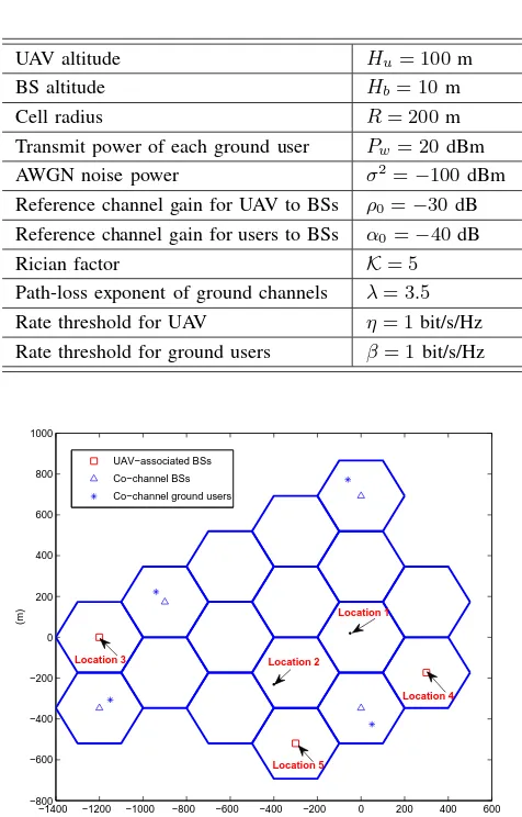
In this section, numerical results are provided to demon-strate the effectiveness of our proposed precoding optimiza-tion scheme. The simulaoptimiza-tion experiments are carried out in MATLAB using CVX. The parameters in the simulation are presented in Table I. Moreover, each BS is located at the center of the cell, while the co-channel ground users are randomly distributed among the cells allocated with the same frequency band as UAV, following a homogeneous Poisson point process. When there exists a co-channel user in a specific cell, the density is 9.62 users/km2. First, we consider a cellular network following the topology in Fig. 2, where a UAV is connected withJ = 3 BSs, andW = 4 active users are using the same frequency band for uplink transmission to their corresponding BSs. As marked in Fig. 2, five UAV locations based on the UAV placement discussion are considered: Location 1 is randomly generated in this cellular region, Location 2 is the geometric center of the three BSs connected with UAV, and particularly Locations 3-5 denote that the UAV is placed above one of its connected BSsj ∈ J, respectively.
The sum rates of UAV and ground users are compared at different UAV locations with iterations in Fig. 3. The
TABLE I SIMULATIONPARAMETERS
UAV altitude Hu= 100m
BS altitude Hb= 10m
Cell radius R= 200m
Transmit power of each ground user Pw= 20dBm
AWGN noise power σ2=−100dBm
Reference channel gain for UAV to BSs ρ0=−30dB
Reference channel gain for users to BSs α0=−40dB
Rician factor K= 5
Path-loss exponent of ground channels λ= 3.5 Rate threshold for UAV η= 1 bit/s/Hz Rate threshold for ground users β= 1bit/s/Hz
−1400 −1200 −1000 −800 −600 −400 −200 0 200 400 600 −800
−600 −400 −200 0 200 400 600 800 1000
(m)
(m)
UAV−associated BSs Co−channel BSs Co−channel ground users
Location 5 Location 1
Location 2
[image:10.612.318.556.68.440.2]Location 4 Location 3
Fig. 2. Topology of cellular-connected UAV network.J= 3andW= 4.
maximum transmit power of UAV is set to be Pmu = 27
dBm, and the number of antennas equipped at UAV isM = 4. From the results, we can see that the proposed Algorithm 1 can converge quickly for all the considered UAV locations.In addition, we can also observe that the performance under the case where the location of UAV is above a certain UAV-connected BS is better than that with the geometric center of UAV-connected BSs and that with the random location, which is consistent with our discussion in Section IV. Since Location 3 achieves the best rate performance among the five locations, it is adopted for the UAV in the following simulations.
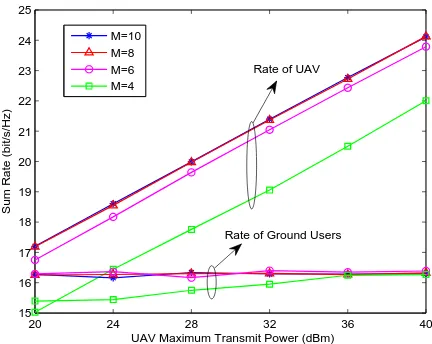
In Fig. 4, we compare the uplink sum rate of UAV and co-channel ground users with different values of the UAV maximum transmit power Pmu and the number of antennas
equipped at UAV M. From the results, it can be observed that the network sum rate increases with Pmu and M due
to the fact that more resource of power and antennas can be exploited for the UAV precoding optimization to achieve better rate performance. To gain more insights, the sum rate of UAV and the sum rate of the co-channel users are compared with different values of the UAV maximum transmit power Pmu
[image:10.612.322.548.251.444.2]1 2 3 4 5 6 7 8 9 10 11 12 13 14 15
Number of Iterations
0 5 10 15 20 25 30 35 40
Sum Rate (bit/s/Hz)
[image:11.612.328.546.56.233.2]Location 1 Location 2 Location 3 Location 4 Location 5
Fig. 3. The convergence of Algorithm 1 with different locations of UAV.
20 24 28 32 36 40 30
32 34 36 38 40 42
UAV Maximum Transmit Power (dBm)
Sum Rate of UAV and Ground Users (bit/s/Hz)
M=10 M=8 M=6 M=4
Fig. 4. Comparison of the sum rate of UAV and co-channel users with differentPmuandM.
20 24 28 32 36 40 15
16 17 18 19 20 21 22 23 24 25
UAV Maximum Transmit Power (dBm)
Sum Rate (bit/s/Hz)
M=10 M=8 M=6 M=4
Rate of UAV
[image:11.612.66.284.66.246.2]Rate of Ground Users
Fig. 5. Comparison of the sum rate of UAV and the sum rate of the co-channel users with differentPmuandM.
4 5 6 7 8 9 10
Number of Antennas at UAV
10 15 20 25 30 35 40
Transmission Rate (bit/s/Hz)
P
m u=30dBm,Sum Rate
P
m u=20dBm, Sum Rate
P
m u=30dBm, Rate of UAV
P
m u=20dBm, Rate of UAV
P
m u=30dBm, Rate of Ground Users
P
[image:11.612.64.282.300.473.2]m u=20dBm, Rate of Ground Users
Fig. 6. Comparison of the network sum rate, the sum rate of UAV and the sum rate of ground users with different number of antennas at UAV andPmu.
results, we can see that the sum rate of UAV increases with its transmit power Pmu while the sum rate of ground users
remains almost unchanged with Pmu. This is because higher
Pmu means higher received SINR for the UAV transmission
at its connected BSs, and thus, a higher UAV sum rate can be achieved. On the other hand, althoughPmu becomes higher,
the UAV precoding optimization can be exploited to avoid severe interference from the UAV to the BSs associated with the co-channel users, with the rate thresholdβ guaranteed.
In Fig. 6, the network sum rate, the sum rate of UAV and the sum rate of ground users are compared with different numbers of antennas at UAV, with Pmu = 20 dBm and 30 dBm,
respectively. From the results, we can see that the sum rate first increases with M, and then remains almost unchanged when the antennas at UAV are sufficient. Specifically, the sum rate of UAV increases withM andPmuwhile the sum rate of
ground users has no significant change.This is due to the fact that the sum rate of UAV largely depends on the precoding vectors and increases with the transmit power and the number of antennas of UAV, which is consistent with the results in Fig. 5. For ground users, only the interference from UAV needs to be well controlled via the precoding optimization to guarantee their rate requirements.
In Fig. 7, the orthogonal multiple access (OMA) scheme is compared as a benchmark to demonstrate the effectiveness of our proposed scheme. For the OMA scheme, the UAV transmits to the J BSs via time division multiple access (TDMA), and other settings are the same as those of the proposed scheme. It can be observed that the proposed scheme can achieve higher performance in terms of the network sum rate, the sum rate of UAV and the sum rate of ground users, which verifies the superiority of the proposed scheme. It is worth noting that the sum rate of ground users in the proposed scheme is much higher than that of the OMA scheme because of the SIC used at the co-channel BSs. Moreover, the sum rate of ground users in the OMA scheme degrades withPmu, due
[image:11.612.65.281.539.711.2]20 24 28 32 36 40
UAV Maximum Transmit Power (dBm)
0 5 10 15 20 25 30 35 40
Transmission Rate (bit/s/Hz)
[image:12.612.320.551.51.232.2]Proposed scheme, Sum Rate OMA scheme, Sum Rate Proposed scheme, Rate of UAV OMA scheme, Rate of UAV Proposed scheme, Rate of Ground Users OMA scheme, Rate of Ground Uers
Fig. 7. Comparison of the network sum rate, the sum rate of UAV and the sum rate of ground users of the proposed scheme and the OMA scheme, with differentPmu.M= 6.
20 24 28 32 36 40
UAV Maximum Transmit Power (dBm)
10 15 20 25 30 35 40
Transmission Rate (bit/s/Hz)
Proposed Scheme, Sum Rate Without SIC, Sum Rate Proposed Scheme, Rate of UAV Without SIC, Rate of UAV
[image:12.612.67.286.53.232.2]Proposed Scheme, Rate of Ground Users Without SIC, Rate of Ground Users
Fig. 8. Comparison of the network sum rate, the sum rate of UAV and the sum rate of ground users of the proposed scheme and the scheme without SIC, with differentPmu.M= 6.
is compared with the precoding optimization scheme without SIC at the co-channel BSs in Fig. 8. M = 6. Both of the two schemes employ NOMA for UAV’s uplink transmission and perform SIC at the UAV-connected BSs. From the results, we can see that the proposed scheme can achieve higher network sum rate than the scheme without SIC with different Pmu, which results from the higher sum rate of UAV in the
proposed scheme. As for the sum rate of ground users, the performance of the two schemes is almost the same. This is because it is only affected by the interference from UAV, which can be well managed via precoding optimization or SIC to guarantee the rate threshold β. Specifically, in the scheme without SIC, the interference can be only managed via precoding optimization, and thus, the sum rate of UAV will be decreased as a compromise.
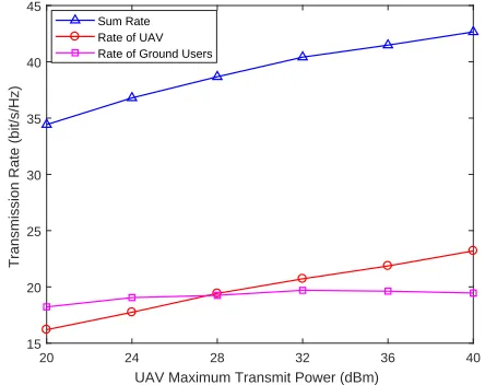
To further verify the effectiveness of our proposed scheme, we consider a more complex network topology with J = 4
UAV-connected BSs and W = 5 co-channel users as shown in Fig. 9. Other parameters are set the same as those of the
−1000 −500 0 500 1000 −1200
−1000 −800 −600 −400 −200 0 200 400 600 800
(m)
(m)
[image:12.612.326.548.286.462.2]UAV−associated BSs Co−channel BSs Co−channel ground users UAV
Fig. 9. Topology of cellular-connected UAV network.J= 4andW= 5.
20 24 28 32 36 40
UAV Maximum Transmit Power (dBm)
15 20 25 30 35 40 45
Transmission Rate (bit/s/Hz)
Sum Rate Rate of UAV Rate of Ground Users
Fig. 10. Comparison of the network sum rate, the sum rate of UAV and the sum rate of co-channel users with differentPmu.M= 6.
topology in Fig. 2. In Fig. 10, the network sum rate, the sum rate of UAV and the sum rate of ground users are compared with differentPmu according to the topology in Fig. 9.M = 6. From the results, we can see that the network sum rate increases with Pmu, which mainly results from the increase
of the sum rate of UAV. For the sum rate of ground users, it only increases sightly withPmu.
VI. CONCLUSIONS
[image:12.612.65.286.286.462.2]of approximate transformations. As a result, the solution to the precoding optimization problem can be obtained by running the proposed iterative algorithm based on SOCP with low complexity. Simulation results are presented to validate the effectiveness of our proposed precoding optimization scheme. In the future work, machine learning and deep learning can be utilized to improve the performance of cellular-connected UAV networks according to [35]–[37].
REFERENCES
[1] X. Pang, N. Zhao, W. Zhang, Y. Chen, Z. Ding, and F. Adachi, “Precoding optimization for NOMA UAV with cellular connections,” inProc. IEEE PIMRC’19, pp. 1–6, Istanbul, Turkey, Sept. 2019. [2] Y. Zeng, R. Zhang, and T. J. Lim, “Wireless communications with
unmanned aerial vehicles: opportunities and challenges,”IEEE Commun. Mag., vol. 54, no. 5, pp. 36–42, May 2016.
[3] D. Darsena, G. Gelli, I. Iudice, and F. Verde, “Equalization techniques of control and non-payload communication links for unmanned aerial vehicles,”IEEE Access, vol. 6, pp. 4485–4496, Feb. 2018.
[4] J. Wang, C. Jiang, Z. Han, Y. Ren, R. G. Maunder, and L. Hanzo, “Taking drones to the next level: Cooperative distributed unmanned-aerial-vehicular networks for small and mini drones,”IEEE Veh. Technol. Mag., vol. 12, no. 3, pp. 73–82, Sept. 2017.
[5] A. A. Khuwaja, Y. Chen, N. Zhao, M. Alouini, and P. Dobbins, “A survey of channel modeling for UAV communications,”IEEE Comm. Surveys Tuts., vol. 20, no. 4, pp. 2804–2821, 2018.
[6] J. Lyu, Y. Zeng, R. Zhang, and T. J. Lim, “Placement optimization of UAV-mounted mobile base stations,”IEEE Commun. Lett., vol. 21, no. 3, pp. 604–607, Mar. 2017.
[7] Y. Zeng, R. Zhang, and T. J. Lim, “Throughput maximization for UAV-enabled mobile relaying systems,”IEEE Trans. Commun., vol. 64, no. 12, pp. 4983–4996, Dec. 2016.
[8] N. Zhao, W. Lu, M. Sheng, Y. Chen, J. Tang, F. R. Yu, and K. Wong, “UAV-assisted emergency networks in disasters,”IEEE Wireless Com-mun., vol. 26, no. 1, pp. 45–51, Feb. 2019.
[9] F. Cheng, S. Zhang , Z. Li, Y. Chen, N. Zhao, R. Yu, and V. C. M. Leung, “UAV trajectory optimization for data offloading at the edge of multiple cells,”IEEE Trans. Veh. Technol., vol. 67, no. 7, pp. 6732–6736, Jul. 2018.
[10] Q. Wu, Y. Zeng, and R. Zhang, “Joint trajectory and communication design for multi-UAV enabled wireless networks,”IEEE Trans. Wireless Commun., vol. 17, no. 3, pp. 2109–2121, Jan. 2018.
[11] Y. Cai, F. Cui, Q. Shi, M. Zhao, and G. Y. Li, “Dual-uav-enabled secure communications: Joint trajectory design and user scheduling,”IEEE J. Sel. Areas Commun., vol. 36, no. 9, pp. 1972–1985, Sept. 2018. [12] Y. Zeng and R. Zhang, “Energy-efficient UAV communication with
trajectory optimization,”IEEE Trans. Wireless Commun., vol. 16, no. 6, pp. 3747–3760, Jun. 2017.
[13] Z. Xiao, P. Xia, and X. Xia, “Enabling UAV cellular with millimeter-wave communication: potentials and approaches,”IEEE Commun. Mag., vol. 54, no. 5, pp. 66–73, May 2016.
[14] J. Zhao, F. Gao, L. Kuang, Q. Wu, and W. Jia, “Channel tracking with flight control system for UAV mmWave MIMO communications,”IEEE Commun. Lett., vol. 22, no. 6, pp. 1224–1227, Jun. 2018.
[15] M. Chen, M. Mozaffari, W. Saad, C. Yin, M. Debbah, and C. S. Hong, “Caching in the sky: Proactive deployment of cache-enabled unmanned aerial vehicles for optimized quality-of-experience,”IEEE J. Sel. Areas Commun., vol. 35, no. 5, pp. 1046–1061, May 2017.
[16] N. Zhao, F. R. Yu, L. Fan, Y. Chen, J. Tang, A. Nallanathan, and V. C. M. Leung, “Caching unmanned aerial vehicle-enabled small-cell networks: Employing energy-efficient methods that store and retrieve popular content,”IEEE Veh. Technol. Mag., vol. 14, no. 1, pp. 71–79, Mar. 2019.
[17] Y. Zeng, J. Lyu, and R. Zhang, “Cellular-connected UAV: Potential, chal-lenges, and promising technologies,”IEEE Wireless Commun., vol. 26, no. 1, pp. 120–127, Feb. 2019.
[18] X. Lin, V. Yajnanarayana, S. D. Muruganathan, S. Gao, H. Asplund, H. Maattanen, M. Bergstrom, S. Euler, and Y. E. Wang, “The sky is not the limit: LTE for unmanned aerial vehicles,”IEEE Commun. Mag., vol. 56, no. 4, pp. 204–210, Apr. 2018.
[19] B. V. Der Bergh, A. Chiumento, and S. Pollin, “LTE in the sky: trading off propagation benefits with interference costs for aerial nodes,”IEEE Commun. Mag., vol. 54, no. 5, pp. 44–50, May 2016.
[20] R. Amorim, H. Nguyen, J. Wigard, I. Z. Kov´acs, T. B. Sørensen, D. Z. Biro, M. Sørensen, and P. Mogensen, “Measured uplink interference caused by aerial vehicles in LTE cellular networks,” IEEE Wireless Commun. Lett., vol. 7, no. 6, pp. 958–961, Dec. 2018.
[21] W. Mei, Q. Wu, and R. Zhang, “Cellular-connected UAV: Uplink association, power control and interference coordination,” in Proc. IEEE Globecom’18, pp. 206–212, Abu Dhabi, United Arab Emirates, Dec. 2018.
[22] S. Zhang, Y. Zeng, and R. Zhang, “Cellular-enabled UAV communi-cation: A connectivity-constrained trajectory optimization perspective,” IEEE Trans. Commun., vol. 67, no. 3, pp. 2580–2604, Mar. 2019. [23] Z. Ding, X. Lei, G. K. Karagiannidis, R. Schober, J. Yuan, and V. K.
Bhargava, “A survey on non-orthogonal multiple access for 5G networks: Research challenges and future trends,” IEEE J. Sel. Areas Commun., vol. 35, no. 10, pp. 2181–2195, Oct. 2017.
[24] Z. Ding, Y. Liu, J. Choi, Q. Sun, M. Elkashlan, C.-L. I, and H. V. Poor, “Application of non-orthogonal multiple access in LTE and 5G networks,”IEEE Commun. Mag., vol. 55, no. 2, pp. 185–191, Feb. 2017. [25] Z. Ding, F. Adachi, and H. V. Poor, “The application of MIMO to non-orthogonal multiple access,” IEEE Trans. Wireless Commun., vol. 15, no. 1, pp. 537–552, Jan. 2016.
[26] Y. Liu, Z. Qin, Y. Cai, Y. Gao, G. Y. Li, and A. Nallanathan, “UAV com-munications based on non-orthogonal multiple access,”IEEE Wireless Commun., vol. 26, no. 1, pp. 52–57, Feb. 2019.
[27] N. Zhao, X. Pang, Z. Li, Y. Chen, F. Li, Z. Ding, and M. Alouini, “Joint trajectory and precoding optimization for UAV-assisted NOMA networks,”IEEE Trans. Commun., vol. 67, no. 5, pp. 3723–3735, May 2019.
[28] X. Liu, J. Wang, N. Zhao, Y. Chen, S. Zhang, Z. Ding, and F. R. Yu, “Placement and power allocation for NOMA-UAV networks,”IEEE Wireless Commun. Lett., vol. 8, no. 3, pp. 965–968, Jun. 2019. [29] W. Mei and R. Zhang, “Uplink cooperative NOMA for
cellular-connected UAV,”IEEE J. Sel. Topics Signal Process., vol. 13, no. 3, pp. 644–656, Jun. 2019.
[30] L. Liu, S. Zhang, and R. Zhang, “Cooperative interference cancella-tion for multi-beam UAV uplink communicacancella-tion: A DoF analysis,” in Proc. IEEE Globecom’18, pp. 1–6, Abu Dhabi, United Arab Emirates, Dec. 2018.
[31] A. S. Hamza, S. S. Khalifa, H. S. Hamza, and K. Elsayed, “A survey on inter-cell interference coordination techniques in OFDMA-based cellular networks,”IEEE Commun. Surveys Tuts., vol. 15, no. 4, pp. 1642–1670, Mar. 2013.
[32] M. S. Lobo, L. Vandenberghe, S. Boyd, and H. Lebret, “Applications of second-order cone programming,” Linear Algebra Appl., vol. 248, no. 1-3, pp. 193–228, Nov. 1998.
[33] M. F. Hanif, Z. Ding, T. Ratnarajah, and G. K. Karagiannidis, “A minorization-maximization method for optimizing sum rate in the down-link of non-orthogonal multiple access systems,” IEEE Trans. Signal Process., vol. 64, no. 1, pp. 76–88, Jan. 2016.
[34] Z. Ding, P. Fan, and H. V. Poor, “Impact of user pairing on 5G nonorthogonal multiple-access downlink transmissions,” IEEE Trans. Veh. Technol., vol. 65, no. 8, pp. 6010–6023, Aug. 2016.
[35] M. Chen, W. Saad, and C. Yin, “Liquid state machine learning for resource and cache management in LTE-U unmanned aerial vehicle (UAV) networks,” IEEE Trans. Wireless Commun., vol. 18, no. 3, pp. 1504–1517, Mar. 2019.
[36] U. Challita, A. Ferdowsi, M. Chen, and W. Saad, “Machine learning for wireless connectivity and security of cellular-connected UAVs,” IEEE Wireless Commun., vol. 26, no. 1, pp. 28–35, Feb. 2019.