Ad J 1) van de GOO%
,,":1L .,.
TABLE OF. CONTENTS
page IN'lROIJUCTION 0 0 10 I) " " 0 0 " • {I " V ~ 0 0 c> e • " 0 (I C " 0 It 0 0 e 0 0 () e I.) • 0 " 0 (} 0 f) " " 0 0 CII 0 1
l~n Reason for Timesharingl!l (I 0 3 ( 1 ,: ~ I) 0 <3 0 0 Q 0 0 a (0"''' 0 0 0 0 0 .. 0 (> 0 " 03
B", TS8 Configuration and Consol·~ Cost. 0 <.',~ 0 (} 00(1 \) {> () Q" 0 0 t'l 0,,4 Cc Appro~;u.!h to the PDP .. "S T:tmesll;ring Syst:em ... r}"" Cl G () <3 C t> 0 04
CltAPTER I "" STRU(~'ruRE OF THE HARDWACUt~ (; 0 0 0 ¢ (I 0 ~ 0 I) <> ',' 0 ::; 0 " 0 " 4\ I!I G 7
.A I:) Brief DescTl.ption of the PDP, .. 8 Processor.., 0 0 (j 0 " 0 " 0 «) I) e 7
:80 Primary M.emory (" " 0 () " (I 0 ('! 0 0 <') 'it" 0 " 0 " " :) I) 0 0 " <:) '" " " 1.:1 eo", <) Q 0 e/)o ,,8
C.~ Secondary !J1emory Q 6 (10 G O " ., 0 " " r) (J .;> " 0 I) '.) 0 0) 0 0 " <00 " 0 0 0 I;) 0 0 Ii> 0 0 0 " 9
Dc> :reletype Interface" 0 0 (I (0 <> Cl III 0:; {) .'~ Q Q"" 0 " 0 0 " 0 " 0 0 0 0 C1 ( ) " 0 co 0 g 1 0
GBAY.?TKUt II .." STRUCTURE Oli'
nm
VlRTU~\'L MACHINEc 0 . , coo () 0 ,l Q \) 0 0 12Co Console Control of the Vf.rtu.'ll t42chineo (I G I) ,t. ( I " 0 Co .. ., 0 13
tCHAPTER III - STRUCTURE OF SYSTEM P:lOVIDED FACILITIES
SEEN FROM VIRTUAL MAC; lINE 0 $ .. <) Q 0 0 • IS " 0 Q 0 I) 0 0 .. (> 0 14
lio Conversion of DEC Software" I ) " Q "' .. e .. 0 " 0 0 (I 0 0 < ) " 0 0 0 0 0 0 (;., 14
2", Desk
ea
lculator 0 " I) ~ 0 0 7 0 0 0 0 G <) <) " 0 " 0 Q I) (I 0 ., 0 0 " 0 0 \) 153" Assemblers: Macro anr"\ Palo 0 I'l 0." 0 0 0 0 0 " {> (I 0 0 0 0 15
4" DDT. " 0 " 10 a '" .., 0 0 0 0 ( • • C 0 I) IS> ~' • (I 0 " 0 Ii> " 0 0 ~ () \) fD 0 0 I) to 0 " " a I) 15
50 Loader II 0 G " 0 0 ~ 0 0 I) e <II iii ,. Q (. 0 (I (I Cl I;) 0 0 II " 0 0 I) <') 0 e G Q III 0 0 () (I 1 S
60 Fortran 0 0 " I) 0 (} 0 0 0 I) ,,. <) 0 I'> ." <) 0 0 0 <:> 0 Q 00 13 <) () . , e 0 () 0 ". 0 0 co 0 a 16
Bu Software to Operate in. Conjw:~etion witb Computer
He t."Works G <) (I ., (I • " 0 G Q 0 I!I (I 0 0 (I :> 0 0 Q 'i Q 0 • C () 0 0 Q () GO., 0 :) C Q I) Go Q Q 0 0 16
1e
Job Flow to
P r o c e s s o r n O O O O Q O O O C I D O G 0 0 0 o G o o e o o 1 6 20 Job Snaring .. " ( I " <II 0 1'>" I) 0 . ' o.!) .. 0 . " , 0 ().., 0 ~ III (\ -:,'0 0 . 0 0 () (> 0 17STRUCTURE OF THE MONI.T(~R 0 0 0 0 0 0 0 0 Q Q 0 a 0 0 I) III \) C l ' 0 c> 18
10 . Resident Programs and. Fileso (1 3 0 GOG 0 (;' 0 e G <> 0 0 Q Q'18
[image:2.618.56.543.63.728.2]Figure 1-1 Figure Ic~2 F1gure 1-3 Figure 1I .. 1
Figure IV..,l
-11-LIST OF FIGURES
page PDP.8 TS8 Conf igura tion 0 0 0 0 e • ~ 0 0 0 .. 0 . . . . 0 0 • • 0 0 0 0 • 0 a 2i;.
PDP-8
MajorRegister Block
Diagramoooooo oooo • • ooo25Data Communications System Block Diagram ••• o<looo,,25
State Diagrs'm of Virtual Machine 0 0 0 . 0 0 I) 0 0 Q ( 1 " . 0 " 0 26
Disc File Structureoe.oooo.oooOOOOgOo.o.oo.Qo.~.27
Figure IV-3" Q • • 0 . 0 0 <II (I 0 III 0 0 I) 0 0 I) eo." • 0 0 4 (I Q G () 0 Q Q '" fll (I I) 0 0 • I) • • " • • ) 0 II 'J .. 28
Figure IV ... 4c:. I'J 0 (1'0 I) 0 G 0 <) 0 0 0 «> • ., .. iIJ CIt 0 " 4 0 (I 0 0 (I 0 0 I) G " <> Q (I .., 0 0 " 0 <.9 • «I' 0 0 I) • '0 ~ I) 28
Figltre IV .. 5., I) it " 0 0 0 0 0 (I 0 0 0 0 0) .., (I 0 ~ 0 I) 0 • I) <II I) 0 () 0 I) 0 0 0 0 .. " 0 " 0 I) • 0 0 0 0 0 0 • 0 .29
Figure IV .. 6 User File Structure 0 0 \) e eo 11.0 GOO 0 0 0 ill & e 0 I I " 0 0 (100 fI 0 o:I~)30
LI:'lT OF APPENDICES
Appendix A ~:tonitor Instl"u,;:tionso o. (I> <I (J G . 0 0 " 0 (I 0 (I . . " 0 0 .. (I (I g " \) (I eo 0) ,,31
Appendix B Current File Informstionoo.o.oo.oo.ooo ... ooo.o~o33
Appendix C Input Output Buffers~ ... e.o.oooo.oo.oooOOOOO~034·
INTR.ODUCTION
SUMMARY
The system described 1n this report is being designed for 10 to 50
users~ depending on the user d~ndso Though the system can stand alone,
it is to work in conjunction with a larger systeme the Remington.Rand
1108-EXEC 8! and the experimental IBM TSS ... 360/61o
[image:4.615.45.595.60.752.2]In a general effort to make computing facilities more available to users and studytbe 'l'anse of Time Shared Computer usage it is desired to design and stu.dy a special purpose time sharing system. using a PDP ... 8 computer at Ca.megie ... Mellon Un1v~rsityo 'lbeconfiguration is sbown in
Figure 1..,,10 It is, ,felt that particular jobs can be selected to best match
particular eomput:f:,ng facilities9 'and this proposal 1s a suggestion for
s11ch an experime:nt 0
A time sharing system is on~ where several simultaneous uS.e:rs have
access to a si~gl.e computer or, 'computer-fa) through a network'? Only a small
degradation in pe'rformance (as,'measUred by problem solving spee,d) occurs
to any user and 8' user is supplied withe'ssentially the same source (before
time sharing) because the facility being requested (computing pafr1er~ data
files~ etco ) requires only a smal:lsmount of the power for a short interval"
11
- The idea of Time SharinS9 though ,very old" It has been attempted on the larger 0
most genera 1 computers!) and as such, the behavior cl such systems for users
with sma 11 jobs entails Ii hi.gh overhead (or cost is large) 0
The system attempts to go beyondtbe obvious case of just'(!oncentratl.ng
messages (either on a character byeharae,ter or a line by line basis) for
"*
Co Stratchey6s paper (1959)0...
2-the larger computers (although doing this function for
only
20 users is worthwhile from an economic viewpoint)oThe system is designed for three specific environments:
10 Companion mode: (used with a larger computer orcomputers)fJt
ao Editing a complete file: Filesreslde in the larger
system and editing is done at periphery because interaction rates are high, and computing capacity required is lowo
b·o Editing only pages ~ Text pages are transferred to the
TS8 and editedo
Co Trivial calculations: desk calculator$! very small ALGOL
and FORTRAN
jobsodoPre-processia89 special editing, and syntuchecking for on-line languages like
Lee,
JOSS~ BASIC~ etco9 prior tointerpretation in a larger machineo
20 Genersl'purposee stand alone time sbaring with very l~lted
capacity (suitable for secondary school or
similar
environ....,mentf) where the computational demands are not extremely high)o
3 (I Base for special purpose stand alone systemsQ E08<1 ~ shared
data collection system; Time Shared Keypunch consoles for data
entry
and transformation; component of a network to concentrate messages~ and do local processing",The virtual machine provides the user with a console (a teletype KSR33
initial1Y)9 a portion of the processor capacity for running 41<. programs
(larger programs~ UP to 64Xp luive to be manased by the ueer)98 open. fixes 9
shared file capacity of 200 ... 400 ,text pages for all users9 and a tape sys~em
A 0 REASONS FOR TIME SHARING
*
There are many commonly promoted reasons for having a time~sh8rlng
8ystemo Some are:
10 Better man~macbine communicatioD;
20 More efficient use of equ~pment and as such;
30 Effectively more computers:8vailable for useo
Better Man-Machine Communication
..
Literature ',on time sharing,' systems states that a time sha:reid computer
seeks to pt'ovid~ better service· to Users,by providing better
man ....
machinecommwli.cations (; '!be program debugg~ng, process can be made moreeffieient
if the user ca,n ,b.e present at j:be eomput~r console and correct m1.stakes
as they occurll Results are available 'very shortlyafterrequests'Q
Efficient Use of· 'Equipme1'!~
A problem common to all cOtnputers is that input-output equipment
l.\8u811y bass ',ra'te of transfer,'much lowe'X', tbau the cycle time of: ·.the com." puter" This means that the computer" can be limited during input .. ?output operations 0
A time shar~ng system will make the whole process more effi~iet~t by
allowing several'
:rio
devices ac:tiveat onceo '!bisS) of course~ is' at thecoa~ of overhead~
!:!2~ Co~pute:r Use Availab!!
In a time shared system asst.wing the slower in-out device~o.ne effectively has a number of computers equal to the number of time-shared t.":oMoleso Con.".
~C::WUll
See appendix in Time Shared Co!puter~9 Go Bell; ARPA Report~ Carnegie
sidering that an additional console is much cheaper than an additional computer, a time shared system gives both more efficient operstionand increased computing capac it yo
!~ ~ TS8 CONFIGURATION AND CONSOLE COST
In the case of the TS8~ we assume a hardware configuration of $509000 .. $7590009 and
I
user cost of between $1000 and $7500 for 10 to SO userso Now, while these costs are subst.ntlally lower than for largescale systems ($209000 - $SO~OOO
I
connected. ~onsole) they are at thecost threshold of a stand-alone computer «$109000)0
Substantially more facilities are being provided 9 lncluding user
fi1es9 magnetic tapes 9 inter-console communication$) and a larger basic
facl1ityo In factg the two facilities it does not provide are: the r~u
ning of large9 Wlorganized programs and a large capacity filing systemo
The approach to filing does glvethe user the same ability that large systems provideo
Co APPROACH TO mE PDP-8 TIME SBARlNG SYSTEM
10 Method.!..of Sharifll
Many choices are available·for implementing the program and .memory sharing for a Time Shared Systemo These range from pure multiprogramming
to program swappiuso
The proposed method for accomplishing the proje~t is to use both multi=
programming and program swappingo The primary memory size (3 X 4096 words)
is such that it contains 2 (ls-096 word) programso A disk memory is used to store files and waiting programso While a program isrunning~ in core~
-5-We assume that jobs entering the system require very little ~omputiDg
(loeo~ can be done while swapping occurs)>> We take the following example
for
SO
users to do editinsoThe machine capaeity required (worst case) for managing -!1 typewrU;er
line is approximately Oo~/11neo - -2~
The machine overhead in the monitor (per ~se~) 1s estimated to be less t1lan 006(. (Asswnea that 30 jobs are run /seeoD.do ) - - - co
lhe system degradation 1f ~e drwa is transferriDg continuously
1s
(105
MS /word stolen from core/405
Hsec word transfer rate)o - - - -3~The remaining available capaccity for processing is: - ... - ... "'" -16c(
!~=quired Ca~city
Assuming
SO
user jobs are entering the system eaoh 8 sec (1 line oftext) / jabi' and 10 MS of eomputing power 1s required for eacb request@ thetll
the average eomputing capacity required is:
001 se~. o~~~ut1~g X 50 jobs m' .065 sec of computing = ~ ~
job 8 sec sec 2 'l
The computing job load is only 50 jobs /S sec or
~
jobs /secoThe above s~p11fication assumes perfect ordering of the r.equestso
Also~ in a given 34 MS period, dle swap t~e, only about 5.1 MS(or 34 MS X 16()
of computing power (cycles to the processor) i.s availableo 'rhis timeD or
capacity, when a new job is being loaded is called the IlImini.mum jobV' or 50 1 MSo
This suggests that the system will not be disc bound, but compute boundo
Since the job load is far less than the disk capacity (30 jobs Isec)~ the
capacity loss due to disk transfers will be less or approximately only
1
~
X 34tfo or fA.fj leaving4~
computing capacity available instead of 1&16.,30
A simulation has been made for the system and is included in Appendix 1)"
For the simulation, assumptions about jobs were such that the average
response was limited by disk swap timeo The simulation also considered
cases when the capacity lrequired was beyond the "minimum jobU 0
20 Operation Under Time Sharieg
throughout the design of this system the hardware changes from a
user8s point of view will be a minimum such that programs lfhicb were
running in the non-time-shared mode can be run in the time-shared mode
(wi~ only few modifications)o On the other hand the system provides
many more facilities which were not available in the absolute machine 0
We define several machines a.ccording to the following figureg 'tbe
Absolute Machines the Virtual Machine9 the User Machines and the User
Defined Machineso
processor
memories teletypes entries to other systems
Absolute
resident monitor non""re.sident monitor
~~~~m=_~e;:
.. ·
,
User Programs Virtual Machine
CHAPTER 1
[image:10.617.53.596.48.769.2]STRUCTURE OF 1'HE HAlmWARE
Figure 10.1 shows the PDP-8 hardware structure Q The
mia.imumconfigura-tioD has 3 X 4K of core memory t 20 teletypes s 1 disc file and 2 tape
units 0 Except for some additional switches and special modifications to
the PDP .. 8 processor, the hardware is s·tandard 0
111e PDP ... 8 1s a smallS) high speedS) solid state circuit computer gand·
in its standard configuration has it 4K» 12 bit wot"d lo5t),s,cycle time core
memory 0
A 0 ·Brief Description of the PDP .. 8. Proces$.2!
A block diagram of the basic;: ·PDP-8 .processor ~\~n from the?DP .... 8
handbook i~ given inFlgure 140 From this we see that it is built up out
of the following blocks:
*
1 I) Accumulation (Ae)
*
20 Link (L)
*
30 Program Counter (PC)
*
40 Memory Address Reg:Lstel- (MA)
50 Memory Buffer Register (MB)
60 InstruetionRegister . (IR)
The additional blacks are:
l~ Switch Register (SR)
*
20
Major State Generator3. OUtput bus drivers
40 Core Memory
*
The core memory 1s d1videdinto pages of 128 wordso
Instructions are single address$) one word longo The first 3 bits
specify the operation and the remainder is used for addressingo In in ..
structions Which do not take an address '~e ~ bits are used for
micro-prograDDing 0 In the caee 1)£ ,an input/output instruc t10u they, spec ify .,the
I/O device (up 'to 64 devices) and microprogram a set of
I/O
eouuandpulseso
Because· the memory has a palged' structure 9 the 9 bits for addresslng
are used as
follows:
10 The fir·at bit indicates indirect addressingo
,20 The sec.end bit indicates current page or page 00
30 The remaining 7 bits are used to determine the location or line
within a page 0
Incase of indirect address:lngS) the full 12 bits are used to specify
a location in. the 4K of core 0
ibe core memory can be increased in units of 4K9 until 32Ko In this
case two 3 bit registers are used to concatenate w1ththe processorlls address
to form a 15 bit address 0 Communication among 4K memory modules is fa:M.y
difficul.to
Hardware mll1tiply and divide circuitry is not standardtlnd is ~id.1&:~,~l(:!
r:l~ ~l-:)~}ltfl~o"
Bo Primary l!!m0ry and Communication betwe.ep Primary and Seconda~~,,! .
From Figure 1,:·1 we see that the system has 3 X 4K of core memory Q The
resident part of the monitor is stored in 4K and the resulting
aK
are. usedto contain 2 4K (or smaller) programs; one of which is being rWl while the
A data br~8k facilitY9
the
DM01~ isa switch which allowsseveral
processors on controls to directly 8<:cess the core memory I) The '(""rd
access interval
can be as short as 1
05
tJS
/word
QCo ~econdary Memory
Two kinds of secondary memory are used: (See Figure 1) They are~
1 Q Disc Memory
20 Magnetic Tape Memory
lo~
the disc memory ~1il1 be used for2purposesg
(1) Swapping device
(2) Storage of sya'tam files and tempc:n:ary user fi.les I)
The fixed head (64 beads or tracks) disc memory is tit Data Disc Inco
model 1'-60 The average access time is 1606 llisecQ and the transfer rate
1 .. s 4..,5 tJ.sec /word (12-hit word)e with 8192 words stored per tracko
The capa:~;ity of the disc i84096 blocks of 128 worda or rOtlghly~ 005
mill:ton wordso
Th.e smallest amoUt~!.; of infol:"m8.tioll. which can be l-rritten. OR! t>r read
from the disc is 1 page ~ 128 wordso
Since the disc and its controller T.eq~lire access to memory eac.h 40 5 l>1.~ec 9
approximately 66% of the machillecapacity .ts available while the disc is
20 M!Snet~. Tae,.e ~mo~
Two tape units liil1 be connected to the system" The 2 unit:.s &lre the DEC Tape Dual Transport type 555 tc.pgether w:l.th the controller DEC Tape
Control Type 5520
The capacity of a standard tape 1s 1400 pages!#; 00 18 millionWt;~)rdE:h~
Since data on the tape 1s ,addressable and replaceable (unlik.estandard
'IBM ,format tape), a tape can bc!', u$ed
for
file storagee d1rectories9 etcoDo T!11etlpe Interface
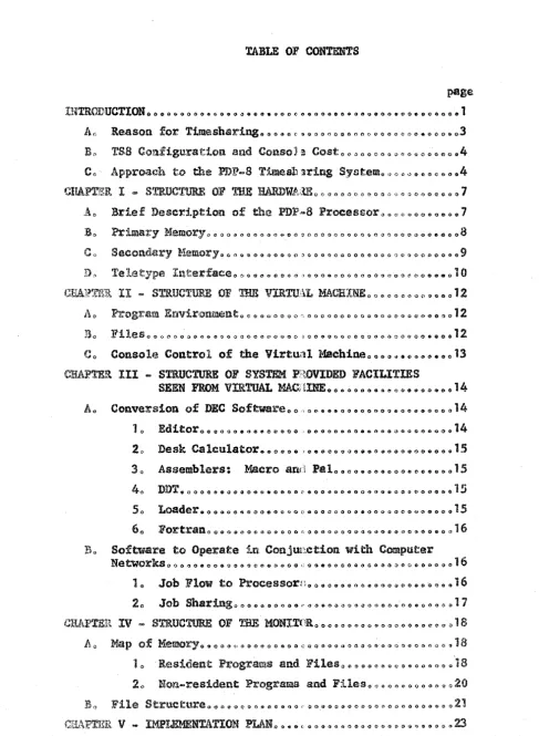
The Telety~e,Interface us~d is'the Data COmDlunications Systems Type 680
from DECo ibis system is built, up out of the following units: ,(See Figure f-<!) 0
10 Data Line Interface 681
20
Serial Line Multiplexer 6853 Q Ma tricon patch !lanel 684
40 Teletype Conne.~t,::r; panel 682
5Q Te legraph level conve:rtor 6830
The 680 allOWs up to 118 tel~ty~s to be connected' t,:;.). thePDP-Bo
The 631 controls ,and executes t7;81)Smis,sion and reception of telefFype in ...
formation between tbecomputer Il~d the type 680 system.., In order, to do
this it adds ~t instructions
to
~he instruction set and takes 274 +7N corelocations of program (N ~ number:'. 'of, teletypes connected) 8s,suming' 8 bit
teletype lines 'are usedo
The 685 is. simply a switcl which allows the 681 to beconne©'tec with
any of the 64 teletypeso
Eo b!odificstionsto the Basic Processor IIlCq I ,~
10 . Addition of memory e:-c.t;}rAsion control (s,tandard option)
2;; Data Line Interface (Eltandard option)
1 0 Memory Extension Control
This 1s the hardware necessary to beahle to specify any of 8 possible
blocks of 4Ko A group of registers together with a set of instructions
is added to the hardwareo
20 Data Line Interface
See part D of current chaptero
30 Trapping Loaic
Ha.rdware will be added which provides for 2 states of running programs:
monitor and user mode.
In user mode I/O instructions and the halt instruction will be trappedg
and control will be transferred to the monitoro
.,.12-CHAPTER II
STRUCTURE OF THE VmTUAL !-lACHINE
This is the structure of the machine as the user sees it <I Figure II ... ' is a simplified model of the virtual machineo '!be different ~lspects of
this are covered under the following headings:
A 0 Program Environment B.. Files
Co Console Control of tbe Virtual Machine ..
A 0 PROGRAM ENVIRONMENT
Programs run on the time-Shared system are almost identical with those
running on the standard
PDP-So
the time-shared system will have morepos-sible 1nstructionso
The size of a running program is ~ 4K of core memory"
By means of program instructions the user is able to transfer to and
from core files or parts of fileso This enables a user to run programs
>
4K words ..B", FILES
The way a file looks like to a user is one consecutive block of the
size of his fileo the maximum size of a file is 64K words" ~rhe minimum
addressable quantity of information in a file is 1 page ~ 128 wordso
The maximum number of files a user can have at a time is 80 This
Co CONSOLE CONTROL OF THE VIRTUAL MACHINE
All control of the virtual machine is done thr.ough the monitoro
Monitor commands are lnlt:iated both from the console and the ,cunning
program 0 A listing of both groups of commands is given in Ap.)endix Ao
Before entering a monitor comrnand the state of the machLle has to be switched from user to monitor mode; this is don,:! by typing a control charactero Upon completion of the monitor instruction the state of the
CHAPTER III
STRUCTURE OF SYSTEM PROVIDED FACILITIES SEEN FROM VIRTUAl. MACHINE
Ao CONVERSI~
or
DEC SOFTWAREThe greatest changes to existing software foreseen in th:J,s study will
not he those necessitated by the time sharing facility but rat.her those influenced by the extended size of the virtual ma\'hine 'to 64K and the
addition of high speed disk file accessingo All the standard software
systems arad subsystems will more naturally reside on the disk~~~ be called
by console monitor commands and initial loaded by the disk file handling
routines for system fileso
10 ~
The current text buffer size in core which limits the si~'~e of text
upon which the Symbolic Editor may function will be extended in the
virt~al macbineo The Editor may be given 2 files containing tilp to 6l.K.
of text instead of the actual text being passed via the paper tape reader,
and paper tape punch. It will be the responsibility of the S~~bolic Editor
to access the Utext pagen.that it needs, via monitor subroutine calls",
Furthermore, if the Editor requires increased work or data space& it w:tll
be required to do its own "paging" of information into core as described
preViotlS 1y 0
TIle I/O functions must be capable of handling the option of either
paper tape ot" disk source filess although this fu.nctioll liJill hE! part of
· ..
1,5-2 0 ~k.. Ca lenia t.Q!,
The Desk Calcu~ptor function will be expected to operate in much the
same manner as it does currently:p perhaps with an extension tc~ tbe reper ...
toire of mathematical function 0
30 f..ssemblers: Macro and PAL
The users of Macro and PAL will be categorized as system programmerso
As such~ they will be expected to know the dynamic state of their programs
and will, therefore, be responsible for performing -the funct:f.ons of up.age
turningU when desired. The assemblers should provide macros for calling
these and the other monitor subroutineso
40 DDT D~ugging System
Only minor alterations are foreseen here 0 Expansion of table sizes
will be made practical by the virtual 64K memory and the "page turnil.1.gtlt
concepts. DDT and the DDT symbol table should be part of a virtual fileD
and as such, invisible to a user programo
50 ~~
The loader must perform the functions presently accomplished maQually
of loading into core the primary executable module 'Of each usel"llg program ..
'!be loader will be controlled by the monitor whicb 'will pass t.o it the parameters indicating the file to be loaded and tbe option sw:U.:ches entered via the monitor console commandso Eventually, tile loader will also have the function of link editing the non-monitor subroutines called by other
languages 0 Each language processor requi.ring a link edit pbase will use
the same loadero Interpreters may require dynamic loading of large sub~
routines 0 Compiled programs usually function best with subroutines resident
...
16-handling both functionsl)
60 !Q.RTRAN Compil~r
ana!!
the FORTRAN Operating SystemMost of the modifications to FORTRAN will be extensions rather than
alterationsn Initially only minor modifications would be made which
allow input and output to be both named fileso The compiler m~ls·t be
designed to handle larger programs than limitation now permit, up to a
64K programo The compiler does not produce machine language object. code9
but rather input to an interpreter under the FORTRAN Operating Systemo
The 'interpreter will be burdened with the table of "paging" program
seg-ments based upon information passed to it in the form of tables by the
FORTRAN compiler., During execution of programs the inter'pre tel' must
check various compiler output tables in order to perform proper address ...
ing ing and checkingo Many of these checks may be turned off in a properly
debugged program. '!bis no-check option is particularly important in the
funct; .. oning of this interpreter ..
The FORTRAN Operating System will now be required to automatically
perform the functions of compile" load and execute by creating and read ...
ing from temporary data files it.:c establishes on disc i.llstead o:€ doing its
i~termediate I/O through paper tape. The load-link edit step should be
accomplished by a call to the Loader from. the FORTRAN OperatingSystemo
SOFTWt\..RE TO OPERATE IN CONJUNCTION WIn! COMPUTi:tR NETWORKS
Job Flow to Processors
~a.r.u"l;:-n== . . I".""""""'~"~
All jobs passing through the PDP-a liill be assigned to a particular
p~ocessor by beiv8 placed in the appropriate queueo The program to
accomplish this function may have the same pri.ority as any other user
... 17 ...
If a central data file is established for all the proeesf.~ors. the
particular CPU assigned to accomplish the current task "ti111 be given
only a pointer in its queue to the job. The particular CPU mtiy then use
either its own intermediate storage devices or those in the shared banko
All buffered output resulting from any CPU execution must be aSSigned
back to the central data file where it will be added to tile PDP-8 queue
of jobs to be output onto peripheral I/O devices. The output functions
will again be accomplished by a user-priority PDP-8 program 'Which will refer. to the monitor Where its job queue will be stored. Storing this
queue in the PDP-8 monitor will el~lnate the need for further interG
program communication.
2.~ l2.!?~_S}lariI!&
Many jobs consist 0·£ several job steps, some of which require high speed' CPUlts, whereas others cannot justify the higb overhead costs of the
same processor. For example9 the job may first be assigned to the PDP ... 8
for editing purposes, then to
the
UNIVAC 1108 for compilation t:lnd execu-tieJu phases. Similarly, a PDP .. 8 assembly language program may first be assigned to the IBM/360 for a high speed assembly and then back to thePDP-B
for e.xecution. When jobs are so shared, status words and conditioncodes must be appended to the jobs and passed between steps. Goo.dit:ton
codes may designate the severity of errors encountered in a job step to
be optionally Checked before execution of the successive stepo
(Implementation of a P.DP-8 assembly language assembler on a larger
machine, as used in the example above, is being planned for early
imple-mentation necessitated by the absence of 3 line printer on the current
.. 18 ....
CHAPTER IV
STRUCTURE OF mE MONITOR
'l'he total amount of core reserved for the resident monitor is 4096 words 0 this will not
be
enough to contain all the programso Certainmonitor programs have to be stored on the disc and
be
run like a user's programo '!be monitor progr,ams which will reside in core permanently are those Which will be used very often and/or are necessary directly to keepthe system runningo
A Q MAP OF MEMORY
10
The monitor programs can be divided into 2 groups:
10 The resident programs and files
20 The non-residen.t programs and f1leso
~sident Prosrams and Files
(1 ) Interrupt identifier routines
(2) Scheduler routines (3) Clock service routines (4) Trap service routines
(5) Disc service routines
{6)
I/O
routines and1/0 buffers
(7) Teletype handling and line edi.ting
101 .... 104 No software is written yet;that is
why
no numbers for required core are availableo105 Disc Service Routineso These routines control the swapping and
to be able to access information from the files, the monitor has resident
a block of 8 words per open f11eo These 8 words will contain enough
cur-rent history ,to make most of the file accesses direct l'1ithout having to
search through the whole file structure as described under partD of
this chaptero
~e information an 8 bit block contains is described in the Appendix~.
"Current Pile lnformation"o
Assuming that on the average there a:re 3 files open per user ,then
given there are 20 users, we Deed 20,'X 3 X 8 gog 60 X 8 =: 460 words
=
308 pages.106
!{o
Routineso This program takes care of the input" output andbuffer service for the teletypes and the high speed paper tape reader puncho
It includes the routines of the 680 teletype interface;
area
for the I/O buffp,r and 2 status words for every I/O deviceoStorage 1srequired for:
,",'\" 680 teletype interface 274 X 7 X 20 ~ 294 words 1O.r. 203 pages
I/O buffer
500 pagesStatus words 22 X 2 • 44 words ~
.2:.ll
pagestotal 7065 pages
The above total does not include a program to pack and unpack the status words and the characters in the buffer and to assign and release
buffers 0
How the
I/O,buffers
and the status words look like is described under tllnputOutput Buffer" in Appencllx C.1070 Teletype Handling an~ Lin~Editip&o
able to do very s~ple editing functions:
(1) De:iting a char~cter
(2) ,Deleting
a
whole' 11noo(3) Recognize~ a carriage return
-20-(4) Recognize an input termination character
(5) Recognize a Character to move into monitor-console com~
munication state_
Point 4 above is added because certain programs allow a user to type in some input string after which the system responds by typing the answer
on the same litle.o Like DDT t . for instance 9 a llows a user to type in the
name of a variable after which the system prints on the same· line the
current value of that variableo
The amount of core needed for buffers and the 680 program can be
computed nOWa
I/O routines with buffers
Current file buffers (seco 105)
Total
7.65 pages
1:.!Q.
pages11045 pages
A special page in the monitor bas to be reserved for bringing in the page containing the userl1s directorY9 for making changes and c<>py certain
parts in the file blockso This ares of 1 page can be used also to bring
in the page with pointers in case of indirecto (See partB of this chaptero)
The area in the 4K free for the programs mentioned under An <, is
Of the 19055 pages9 1 page will be needed to contain a bit table
for disc memory al1ocationo
20 !RD R.esiden~ Programs and Fi~~8
These are~
(1) Syntax Analyzer
(2) Tape handling routines
(3) Error message file.
20 1 The Syntax Analyzer 0 'lb:Ls program analyzes the instructions given to the monitoro Together widb the program, a list of all monitor instructions is stored. Appendix At ''Monitor Instructions", gives a
'listlligof these instructions.
202 Tape Handliy Routines. The'Be include a set of routines to handle the typeSSS DEC tape unit .and: a program to transfer from. files on the disc to .the tape files ~nd vice versa.
2.3 Error Message rl1e.
.1s:
·is a collection oferror
messagesdue to
errors. caused
by s· wrong,use'
of' monitor instructions.204 Main Directory. A search program together with the main directory are stored in one file~ The main directory.containsall the
legal user-numbers.
Bo mE FIlE STRUCTURE
With the File Structure is me'ant the way of access and storing of informat·ion on the disc ·file. Figure IV .... 1 shows the different levels of the file structure together with the 4 sub divisions. These are:
10 NoD. x-esident monitor ·file(s) 20 System directory (binary)
30 System directory (text)
4~ Main directory
As discussed under part C 0·£ chapter I~ the smallest addressable
quantity is 1 page.
1... Non Resident Monitor File(sl
In the resident monitor pointer(s) will be stored pointing directly
to the non resident mon1 ... tor file(s) 0 Toge·ther with thesepof.nt~rs, intO
2" System Director}' (Binary)
'lbis directory will consist of
a
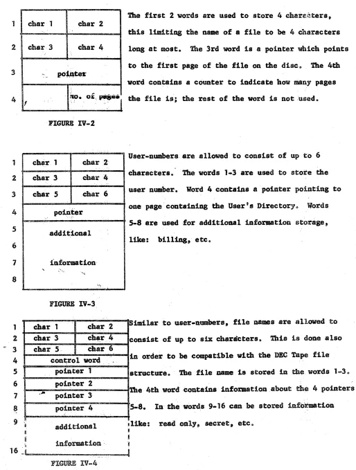
list of 4 word blocks where 1 1~Jlockis used for eV(fJ.ry file in the directory. Figure IV.;2 shows how the 4
words can be used·.
3" System Directory (Text)
This directory will be identica:l to the System Directory (binary) 0
4. Main Direc.tory
In this direc·tory are stored all the legal user .... numberst together
with a pointer to the corresponding. User"s Directory and some additional
information. S:ee 'lgure IV-l.
40 1 Us(!r. Directoryo All the files a user can have on the disc are
contained in this directoryo
Per file a block of 16 words is used. See Figure IV .. 4o The 4
point-era from Figure IV .. 4 can be used ~s direct 01' indirect pointers. ibis is
determined by the control wordo See Figure lV-So The maximwn size of a
file to which can be pointed to directly is 4 X 4 ~ 16Ko Whe:n the indire¢.(t
pointer is used the maximum size of a file can be 64 X 8 pages ~ 64K. Given the fact that we have 1 page for the User Directory and that
it takes a block of 16 words per file9 8 files can be on the disc per
user-number.
[image:25.620.50.557.76.718.2]CHAPTER. V
IMPLBMENTATIONPLAN
The design of this machine 1s such that the system can be used as
a stand alone system or in conjunction with a b1gge·r machine.
The stand alone system will be the first stase in the design. By
January, 1968 the monitor is planned to be written, together with changes
in the existing software package. In parallel with this,. the required
hardware
modifications will
be done.After the system as described itl this pa'per will be
realizedS)
atsome future time modifications
will
be made to use' it in conjunction withP(Arttbmettc)
.. ,~-.~--~~ S(1/0 Bus) K ~ .. ~~~~ T(ASR 33 Teletype)1=- -- - - -- - --+
\~.'.'.'
.'.K'~~.
T(2 .. 0.4kb/
B ... Da ... taphone
~
l
~
K.--=---
T(l'aper tape reader) - - _. . 'K ... -,.~.4~ T(Paper tape punch)
S(DMOl Multiplexor)
where: M=memory. S=swltch, P=processor,
"'-~---~
K=control. and T=Tetminal
~'
M(core) == M(loSMS/w, 4096w, l2b/v) \ . "
M(Data Disc) -~ M(fixed head disk. 405MB/word,
+ \;_
O.34MS,. 219wards) ." 6 . \
M(DECtape) gg M(ad4ressable magnetic tape, 3 X lOb
~~s \
S(PK)c It(SH, 2P, 1 proees£or/unlt time)
S(DM01)
~S(lS,
8P~lP
or k/un1t
time) 8(1/9 Bus) := S(lP, . 64lan· l~!Uftit time)~ ~ Continuo~sclo~ur.e for data transmialsion (1$e.,
non-. time
multiplexed)
. -', Data Transmission between two M at rate of
---== =~= - - H s8condary·o
b
=
bitsW'=
war"
s
=
secok
=
kilo~,;. f·MG(DECt:a~e)(.- """,- -- -- ... - - - - ~.
"'\.
r~
I:
~..
. .~S/
...'.'.'~
.... M L - :...~
' \
'"
~.".
:
.. ; t
.
...- - -
-1.-- -- -;
~ .
\
.
....
7
"'-:'K .:.'-':'·'~~.M(Data Dis~)
/
Hardware System interfa~e
[image:27.794.36.777.35.562.2]FIGURE 1-2. PDP-8 MAJOR REGISTER BLOCK DIAGRAM
[image:28.612.154.548.45.348.2] [image:28.612.149.550.437.680.2]dorman·~
I
I
I
i
I
I
I
I
I
I
I
I
I
I
I
. I
run
swap
t.f ... ,d
input wait
output wait
Char I
I
L~~_______
Run time virtual machine ~~~_____________
~I
ri
F
[image:29.792.106.709.55.553.2]File Structure
User Files
1 2 3 4 1 2 3 4 5 6 1 8 1 2 ~- :3 4 S 6 7 ~ I
9 'I ft
~ '1
char 1 char 2
..
cha·r· 3 char 4
,;' .. po~~te$'
. ,. .. "
oi:~""jl
~O. ' 'FIGuaE IV .. 2
chs·r 1 char 2·
...
char 3 char :4
,.
char 5 char 6
po~·~e·r
'.
add it.lona 1
informatlon-'- ... "
' .. ~ .... ,
.• ~
, .
FIGURE IV-3. -:'.
char 1 char ·2 char 3 cha.r.4
char
s.
cbar·6cont;ro1 word. pointer 1
pointer 2
,.Ita
pointer 3
pointer 4
additional
-28-The first 2 words are used to store 4 chare(~ters,
this limiting the name ofa file to be 4 characters
long at most. 'l'he 3rd word 1s a pointer wbich points
to the first page of the fl1e on the disce The 4th
word con~alns a counter to indicate how many pages
the fl1e 1s; the rest of the word is not ,·usedo
User-numbers are allowed to consist of up
to
6characters 0 The words 1 .. 3 are used to store the
user llumber·. Word 4 contains a pointer pointing to
one page'containing the User's Directory., Words
5-8 are us·ed -for additloaal inforutlon storage t
like: billing, etco
Similar :touser-numbers, file namesareallawedto
consist of up to six cbara"cters 0 This is done also
tn order to be compatible with the DEC Tape file
structure 0 . The file oame 1s stored lnth~ words 1-30
'!be 4tbwordeonta1na information.about thea 4 pointers
5-8. In:tbewords 9-16 can be
storedinformatioQ ~1:Lke:readonlYt
secret, etco [image:31.612.56.570.82.761.2]
-29-'!he control word 4 from the preced .. ing figure is divided ~nto 4 3 ... bit words, a 3-bi1: word. for every pointero
The 3-bit word tells whether the· poin·te.r is used and if so, wef;ller the
corresponding pointer points direct or indi~ectp and in case of direct, to
what size of a block it points.1t
0.. 0
.0. 0 0. l'
0 t
1 0
0.
1
0.
1
0.
' "
pointer not u~ed
points direct to 1 page
points direct :to 8 pages
points direct to 32 pages
points. indirect
When the pointer points indirect it always points to a'l page blocko Half of the words in tbatpage can be used. When a·oy olthe words 1 through 64 are non-zero they are po.inters which point directly to a block of 8 pages, 0
Oo.ly the 1st pointer of the 4 indicated in Figure. IV-S can point
Main
Di:t~e ctory
8w 8w
User's Directory
lp
~
e
,
l
,
II
•
~
LJ
8p
\
1p•
~ 0 w
J
32p
[image:33.792.58.688.72.567.2]1p 8p
..
31-ARaDUA
IDRma~
When' a COCCUI'B ill the
riabt
colU11D the conmaad caa be ia8ued fzomdie
ceuola'~, • .. ·l·."D.P' . . .
I Cbe,,~ caa bef.a8aed
by tIie·:~ • • • • • . . . Inthe
l1at'.'·CO"NWIda . . wittenw1th
a
full _ . in the:tmp1emeiata-t18a llllleDDliioa
wttl
be uaed howage:r.1.
~t20
L1st
3 ..
OpeD A4.
CloaeASo Delete A . 6.
create
A7" Rename,A: .. B
8
D lpad A. B.t: C. Dp,e
118t •
.-f.
fi1... Cmake·
tl1eA acce.sable
'PttC
make·tile .A. :1naccaaab1e Pie
"lete8.fl1e At
p.e
onatea
new
fl18 A p.,Ccall ·file A.; B PoC
Jeadpagea A to A
+
.-1 of disc file C P"Clnto
cere
'starting at page Dlead
1'8.,.
A to A+
B .1 ofcore _ _
d l . file Cetaniag at, page D
100 Load tape
A,B,e,D
11ke Load only from tape 'pC110 Dump tape A,B,C,D like Dump only onto tape
120 Start A start e:kecutlng at eore location A
130 Stop at A stop exec ut
ins
at core location Ac
140 Stop stop executing
c
150 @onttnue continue processing
c
160 Macro A!/B apply macro assembler to file A.
put results into file B 11. Pal A,S like macro
190 Fortran exec. A,B
20. DDT A,B
210 Editor A,B
220 CluI . . .
23 0 Append A,I
24. CPU
250 TIME
26
0 Users27. Assip A
280 Release A 290 Set ~WR.
30. Secret A
31 0 Read only
320 Read on1y.others 330
Free
340
Save
350 Print A36e Read A
370 Rea.d high. speed 3So Punch
-32-.h .... f . . . 1'
eo
_itol' IIOdecoaoataute file. to A
priDt a·tataa .1
-"t._
·pJ:l,,' . tiae"'·· .prlatnamber of aaer.
.8.i8D
clevie.A
re1 •• se device"
set· swiech
resister
declare
fl1e A •• cretdeclare
fl1e A read 001,t1eclaref:l.le A
read
on11 for others·make fil.free
save.
current .... chine state print OD teletype Aread from keyboard A
read from
hiBb
speed reader output onbiBb
speed punch1
2
3
4
5
6
7
8
APPENDIX B
ctJRRINT FILE INPORMATION
As described in Chapter IV 11 part A under Disc Service Rout1.nes ~:r
open file
a blockof 8 words
is storedin the
monitor.The
layoutof
this block 1s shown :LnFlsure B-1.
Information
....-about file
----
-Contr-ol word ....
Pointer 1
Pointer 2
Pointer 3
Pointer- 4
-
-Po1_nter to
ne-xt
block
!be
firsttwo words contain informatioD .about
the file, like: file Dumber-.read only, secret,
etc.
Word 8 contains (if not
=
0)8 poillterto thenext block.
Words 3'.-' are a copy of the corresponding words
from the User's
filedirectory •. In ca_e of
direct all the laformatlon- about thefl1eisavaf.lable1n the monitor. In
ca.e
oflndlrect the firstFIGUR.B B-1
,o,1alter is Ut;\edto point at the- page the (at
.z1tauat
64) ·.pc·inter are stored. and the' 3remain-ing pointers caD; be ueed to polnt a-t ·th:ree 8 pase file blocks. These 3
-pointers are justa cop,.. of -3 of the 64 p,.,ssib1e pointerafrom the page the
-34-APPBNDIX C
DlPDT· OUTPUT BtJnD·
lee.ae.oftha ",ert l1a1ted
-.owt
o·f·0" • ..,.
ava:tlal»le··,t01" thelIOa.ltor pl"olJ:'ams oDl, 5 P . . . s were ~e8erve.for die I/O. buffer.' .
!be buffer area is divided iDto block. of •
wrela.
U8:tna packusteChniques every block will be·' able to store 10 "nete·ra. 8e~ .. Pla~·. 0-.1.
1
2
3
4
, S
6
7
8
.' cbar 1
.char 3
...
char
Schar
7char 9
remaining
2
bits/char
l;f.nkto
next
block:cha1t 2
".' " "
char 4
-.
char 6
cbar 8
. ",\-.,
rib.!' ·10
.••... ~:
•
.,
I
~Ot1l1t-er
FIGURE' C-l
this to 40'
'!be fit-at '6 bi.~8 of .n_, . . :rectal: atoe stored
iA the fiX-at SWon:.. fte re1ia~iD8 2·· :bits/ char.
are stored in wore! 6 aac1 7 •
~ 8·tb word bas aeouatel'·(4 blts) :·to keep track
·of theoumber.: of
stored
charac,ter,' an~:' apointer
to the,next
block.
a.total ·number· of 8 hit blocks 1s:5:.)( 128/8 =: 820.
So thepoiater 'lil' rlp.re 1 h8;S. to be 7. bits lODge
.A full. :lnp.at line
coas1stsout
of 72characters
which' means that the· maximum JliuDber of: ·hlocks for
in·put will be 8. Por output we will restrict
~nease of thehl. speed read~r (300
cbar/seco)
we will r~striet themaximwunumberof blocks to 6
and
1 S .• :respect:f.ve 1,.Prom I/O buffer poiot of view a teletype 1s considered 8S 1 device
hav~ng only 1 buffer' which serve·s as either input or out~t· buffer 0
Somewhere in the
It\On1torinformation.concerning
theteletypes
and"J (' Usa~e ,-,f th~~ 't!'1t~Rf!r '".):t' ~,n~:¥~~t "r~t' (.utput
20 N~~J.ler. Qf blpcl,:~~ ~b~."~ 'buf~\E!!'~~It)p.Iii •• sts of
30
"Q~;p,ter J;o the f:~j~~s~ bl.o«;kot
t;be buffer4.., Po~p.ter
t<>
tb.~ t~~~t hlocJ< ~t t~. buffer5~ The use~~ the
\[/0:
de~,~ce!.
J~Ul@i8ned to..,bU~Ffer~lnt~ is shown io, Figure (;=:3 (J 'I
~----.---,-.---~
8
(\' , n ep.'f;,
-36.
APPENDIX D
'!'he results of a simulation of group.sof people editing.1s shown in
the next pages.
the assumptions made were:
10 'l'be ti_ it takes to typewirte a line is distributed Normal with
expected value. 8 sec and C1 =: 2. The tails
<
1 sec and> 60 secwere cut off.
2. !be computation t~e to process a line has a Normal distribution
with expected va lue := 20 msec and
a
a 10 maec. 1.'he tails <1 0 msecand
>
60 msec were cut off.The printout shows the array wait. which is the time a user has to
wait after entering a full line to be able to enter dba next line. '1he
computation tilllet swapping time and overhead are included inthls waiting
time"
The distribution function· and the cumulative distribution function of
·,
",
-.
04 SEP
67
NUMBER OF' USERS=
wAITe 0]=
O,uWAIT( 61=
o,e
wAIT(12]= 97.5
wAITr1B]= 99.8
WAIT[24l=100.ti
WAyTrJO)=100.G
WAITr361=100,G
NUMBER OF
USERS=
wAITr 0)=
O,liwAITr 61=
o.u
WAIT[121= 92,51
wAITelS]: 99.5
WAIT[241=100.u
WAIT(30)=100.U
wArT[J6J=100.11
NUMBER
OF"USERS=
WAIT[ 0]=
O,GWAIT[ 6]=
o "
, iJWAIT[121= e9.31
wAIT[18J= 98.4
WAIT(24J= 99.8
wAIT(301=100.D
WAIT[361=100,U
NUMBER
OF"USERS=
wAITr
OJ= 0,0WAIT(
6)= O,UwAITr12]= 84.42
WAIT[181= 97.1
WAIT[24J= 99.6
wAITr301=100.0
wAIT(36)=100.0
NUMBER OF
USERS=
wAITr 0)=
OeLwAITr
6)=O,u
. WAYT[12J=
7g e 02wAITr181= 96,6
WAIT[241= 98.9
WAIT[30J=
99.7
WAIT(36)= c}9.9
1U
STEP SIZE:
20
30
40
50
WAITt 1l= 0.0
WAIT' 7J=
0.0WAITt13J= 97.7
WAITl19J=100.0
WAIT[25J=lQO.O
WAIT[311=100.0
WAITI371=10IJ.0
STEP SIze=
WAITE 11=
0.0WAITE 7J=
o
.0
WAIT(13)= 94.21
WAITl19J= 99.7
WAIT(25J=100.0
WAIT[31J=100.0
WAIT[37J=10U.O
STEP SIze:
WAITI lJ=
0.0
WAITI 7J=
0.0WAITE13J= 91.31
WAITI19J= 98.8
WAITI25J= 99.9
WAITI31J=10U.O
WAIT[37J=100.0
STEP SIZe=
WAIT, 11=
o
,0
WAITt 7)=
0.0
WAITI13J= 86.91
WAITI19J=
97.9WAITI25J= 99.9
WAITI31]=100.0
WAITI37J=100.0
STEP SIZE=
WAITt 1]=
o
.0WAITI 7J=
o •
0
WAITI131=
82.82
WA1T119l= 97.0
WAITI25J= 99.1
WAITI31J= 99.6
WAITI37J= 99.9
5MSEC
AVERAGE WAITINGTIMEa
46,46
WAITr
2J-0.0
WAIT! 31=
0.0WAIT[ 8J. 14.89
wAITt
91-
43.86
WAIT(14)= 98.9
WAIT(151. 99.0
WAITf20J=100.0
WAIT[21'.100.0
WAITI261=100.0
WAIT[27J.100.0
WAIT(32)=100.0
WAIT[33~.100.0WAITf36J-100.0
WAIT(391.100.0
5~SEC
AVERAGE WAITINGTIME.
48.42
WAITt
2J.0.0
WAITl 31-
0.0
WAITt 81· 14.09
wAITI 91- 3'.16
WAITr141= 95.1
wAITI1S!- 96.7
WAITt20J= 99.8
WA I T
[21:1=99.9
WAITt26J.100.0
WAIT[27J.100.0
WAITt32J=100.0
WAIT[331·100.0
WAIT[38!=100.0
WAIT[39':100.0
5MSEC
AVERAGE WAITINGTIME.
49.41
WAITt 2). 0.0
wAITt 3J-
0.0
WAITt
8].13.49
WAIT( 91· 38.76
WAIT(14J= 93.71
WA I Tt 15:J= 95.0
WAITI20J= 99.5
WAITI211· 99.7
WAITf26,=100.0
WAIT[271·toO.O
WAIT(32,1I100.0
WAITl331·100.0
WAITf38J-l00.0
WAITl39J.100.0
5MSEC
AVERAGE WAITINGTIME.
51.13
WAITt
2]-0.0
WAITl
31.0.0
WAIT( 8J" 14.09
WAIT(
9J.
37.16
WAITtt4J= 89.71
WA
IT [15:1.
92.11
WAITf20]= 9B.1
WAITI211· 98,7
WAIT[26'.100.0
WAIT(271·100.0
WAITt32J=100.0
WAIT[33'.100.0
WAIT(38)=100.0
WAIT(3~H·100.05MSEC
AVERAGE WAITINGTIMEw
53.17
WAITt 2J.
0.0WAITt 3'. 0.0
WAITt
e,R
12,39
WAITt
9' •
35.26
WAITrl;4J. 85.91
wAIT[15'. 89.01
WA1Tl20J. 91.8
wAITI21J·
98.2
WAIT(26,· 99.4
WAITI27,.
9~.6WAITt321· 99.8
WAIT[331· 99.8
WAITl38J= 99.9
WAIT[39'. 99.9
WAITt 4J=
0.0WA!T[10J= 75.32
WAITr16J= 99.1
WAITr22J=100.0
WAIT(28)=100.0
\IIAIT(34J=100.0
lJAITr40J=100.0
WAIT[ 4)=
0.0
wAJTll0l= 66.53'
WAIT(16)-
97.6WAIT[22J= 99.9
WAITt28J=100.0
tJAtT[34J=100.0
wAITt40J=100.0
WAITt 4)=
0.0
WAIT(10): 63.84
WAITt16J= 96.3
WAIT[221= 99.7
WAIT(28):lo0.0
WA!T[J4)=100.0
WAtT[40J=100.0
WAIT[ 41=
0.0
iJAtT[10J= 61.64
WAIT[16J=
94.21WAIT[22J=
99.2wAITr28l=10o.0
WAIT(34J=100.0
WAIT[40J=100.0
WAITt
4)-
0.0
WAIT[10J= 57.84
WAIT[16J= 92.01
WAITr22J= 98.3
iJAIT[28J=
99.7WAIT[34J= 99.9
WAITt40J=100.0
wAITr·,,_
0.0
WAITf~1J.
96.3
w4IT(17'. 99.3
W411123'.100.0
wAITr29J.1QO.0
W411135'_100.0
w'JTt~1'.100.0
WAITE 5J. 0.0
WAI
T
I111.
89.71
wAITr171.·
98,7W4ITI2:31. 99.9
,,4ITI29J.100,O
W4IT,35'.100.0
",4ITt'11.100.0
WAllt 51. 0,0
wAITf11'.' e.,.21
WAll£171.'
97,5wAITf23'.
99.7
W4ITt29'-100.0
WAITt3!5J.l00.0
",4ITI.l1.100,O
wAITr
5h.0,0
wAITIS-1J.
81. 12;WAITI17'.
96.0wAITt23J.
99.4",AI1129J.100.0
\1141Tr35J.100,O
",4IT(411.100.0
WAITt
5J.
0.0
wA I
T
r
11'
a:16.32'
WAITI~7J.
9-1,41'
WAITtI3'.
98.7WAITi29J. 99,7
•
•
MOnE 3,
I. 1M 1 T S I MIN 0 • 0,) 00 U • + 00, M A X 3.14685. + 01, INT/CO~ 3.14685 ;.01, "AGE 1 OF GRAPH 15i
000 010 "20 J30 040 050 060 o,~ 080 090 100
000 ,----.- ••• ' ---.---
---1---.- -.-.. --.-
-·---~.-··-·--·~···.--·--t---·--··--·-.-·_·-1
001 5 002 5 003 5
004 5
005 5
006 5
007 5
008 A 5 3 4 1
009 A
~ I t i I I f I
I 5
I
t
l'
T
I Il'
I3
1
010
A---·_-- ---
---1---_- -.-.. --_. -.---
--··--···'.5-·-··4-~----.--·-t-·2.--·--1:
011 A 5 4 1 I 3 ,
012 A 1 3 5 ,t I
013 Al 23 4 5 t ,
014 A 21 345 , t
015 1 32 4 5
1
016 1 23 4 5 ,
017
Ai 23 4 5 I
1
018
A
14 51
019 A5 4 ,
a
2 0 2435 - • • • - • - .. - - - .. - - - I - - - • - - - ... - , ... ., - .. - - .. ~ - .. • ,. - .... - - - .. - • .. - .. • .., • • • • • - ... - -t, - - • • •
"'!t .. • - " ' - • • • • - • ..-021 254 I
022 5 4 1
-,---~0~2~3~3~5~----~~---~---~---~---~---~---~---1~·.---~---~---• 024 35 I
025 35 t
026 45
1
027 45
t
028 5 I
029 5 t
030 ,----_._.- --- •• ---- ---.-.--- ---.- -~---.- -.---
---·--···,_·---1--···_·_·
-.-.---.-031 5 I
032 5 1
033 5 1
034 5 t
035 5 Ir '1
036 5 I 1
037 5 I 1
038 5 • 1
039 5 1
1
040 5--·~--·-~ - •• ---.-- ---.-.--. ---.-
---"---W·
---1---"---.-1-.·.---1----._·--1-·-.. ·_·-1
041 5----.- •••
-.~---~-- -~-~--- --.----,~ .~-.--~.- -··~-~---I·_·w~_·.·'.··.~-·~_I__ ·_"._·_·'···.··· __ '
... * ...
'*
*
* ...
*
* *
* ... •
*
* * ... *
END OF' GRAPH NUMBER 15 •*
'* • •
* ..
*
'* •
'* •
* .•
*
* .'
'* ...
* .' ... *: •WAITINGTIM9
DISTRIBUTION
VERTICAL SCALIa 5MSeC/STEP
NUMBER
OF"
IIEOPLE EDITING-
l;.Pl..OTNUMBER
· .... 0
•
•
•
•
MOnE 3 ..
L.IMIT
S I MIN 0 • 0 '; 000 • + 00 ..MAX
1.00000. + 02, INT/CO~1.00000
~+oo,000 010 020 030 040 050 060 070
----.-
..
-
---
---~--- ---~----
.--.--~..
-
..
-~---.
...•••...
001 5
002 , 003 5
004 5
005 5
006 5
007 5
008 A
009 A
011
A
012 A
013 A
014 A 015 A
016 A
017
A
018 A
019 A
I
I
I
I I
,
I,
II I
5341 I I
I 5 4 :3 I 1
~---.-.-.
-_._---
-~---..
-~~.--
-~-.---.- --.--~-I i 080,
,
,
II
I
t 1 t5 I 4
' I
,
,
4I 1 1 t I 1
----.-.-- ._---
--~"--- ---~----
.•...
-.----~-.
.
--.--
..
-
..
-.---
'-~..
~090 100
3 2 1 I
31 2 1 I
4 13 2 1 I
5
•
:,2 1 t5 , -4
:5
2 1 I----l 5
•
:3 211I -5 4 321
I 53 2:
I 5432'
021 A I 543,
022 A I 543:
023 A
t
53:024 A
t
54·025 A 'I 54·
026 A t 54,
027 A
I
51028 A I "
029 A , "
o ----.- •••
-.--.--~- -~---.--- --~~-.- ~.••• ---_.
-.--~~.--.- ••
-~•• - ••
"._-·~_I__ ••
"._.·-I.·· •• _. __
5r
031 A I I 5\
032 A I I "
033 A I 1 ;;
034 A I I 3;
035 A I 1 5\
036 A I t 51
037 A I
t
5;038 A I '. "
039 A I 1 5:
o
0
A~---.-.--...
w _ _ _ ~_ ---~-_ _ _ _ ---_~ _ _ .~ .~-• • -~-- -_---~- • • _ . _ • • _ _ • • M._-._~__ .. " ....
J • • • • • • • • • _ :041 A---~.-·-- -.--- --- •• ---- -.---~- .~--.--.-I---I~--.--