warwick.ac.uk/lib-publications
Original citation:
Jeffs, James, McGordon, Andrew, Widanage, Widanalage Dhammika, Robinson, Simon and
Picarelli, Alessandro (2018) Use of a thermal battery with a heat pump for low temperature
electric vehicle operation. In: 2017 IEEE Vehicle Power and Propulsion Conference (VPPC),
Belfort, France, 11-14 Dec 2017 ISBN 9781538613177. doi:10.1109/VPPC.2017.8330932
Permanent WRAP URL:
http://wrap.warwick.ac.uk/103686
Copyright and reuse:
The Warwick Research Archive Portal (WRAP) makes this work by researchers of the
University of Warwick available open access under the following conditions. Copyright ©
and all moral rights to the version of the paper presented here belong to the individual
author(s) and/or other copyright owners. To the extent reasonable and practicable the
material made available in WRAP has been checked for eligibility before being made
available.
Copies of full items can be used for personal research or study, educational, or not-for profit
purposes without prior permission or charge. Provided that the authors, title and full
bibliographic details are credited, a hyperlink and/or URL is given for the original metadata
page and the content is not changed in any way.
Publisher’s statement:
© 2018 IEEE. Personal use of this material is permitted. Permission from IEEE must be
obtained for all other uses, in any current or future media, including reprinting
/republishing this material for advertising or promotional purposes, creating new collective
works, for resale or redistribution to servers or lists, or reuse of any copyrighted component
of this work in other works.
A note on versions:
The version presented here may differ from the published version or, version of record, if
you wish to cite this item you are advised to consult the publisher’s version. Please see the
‘permanent WRAP url’ above for details on accessing the published version and note that
access may require a subscription.
Use of a Thermal Battery with a Heat Pump for
Low Temperature Electric Vehicle Operation
James Jeffs
WMG Warwick University Coventry, United Kingdom Email: J.Jeffs@warwick.ac.uk
Dr. Andrew McGordon
WMG Warwick University Coventry, United Kingdom Email: A.McGordon@warwick.ac.uk
Dr. W. Dhammika Widanage
WMG Warwick University Coventry, United Kingdom
Email: Dhammika.Widanalage@warwick.ac.uk
Dr. Simon Robinson
Jaguar Land Rover
Email: SRobin43@jaguarlandrover.com
Alessandro Picarelli
Claytex Services ltd.
Email: Alessandro.Picarelli@claytex.com
Abstract—Below 10◦C, electric vehicles suffer from reduced range, which can be as severe as a 70% reduction (at -26◦C). This is due to reduced battery performance at low temperatures and increased cabin heating demand. Heat pumps have been shown to have good steady state performance, but suffer slow and inefficient transients, while thermal storage has been shown to provide large heat flows and reduced warm up times, but space for such thermal storage is limited. Here a heat pump is combined with an optimally designed thermal battery and the simulated results are presented with improvements to energy consumption demonstrated.
I. INTRODUCTION
One common concern for electric vehicle owners is the lim-ited range, especially for operation during the winter months or in cold climates [1]. Operatation below 10◦C causes an increased demand in cabin heating, thus increasing power drawn from the battery, hence reducing electrical energy availability for propulsion [2], [3]. The cold conditions also reduce the performance of the electric battery, leading to a further reduction in range [4]. These two low temperature effects combine to give a range loss which can go up to 70% at -26◦C [2].
A. Cold Climate Operational Challenges
The difficulties of operating electric vehicles in tempera-tures below 0◦C can be separated into two categories, the heating load and low temperature battery performance. When considering the range of electric vehicles in cold climates, the dominant effect of temperature on the battery is the reduction in charge capacity. Many capacity tests have been conducted at low temperatures from both cell manufactures and independent researchers. A general consensus to this research is a 20% to
40% reduction in capacity at −20◦C [4], [5], [6].
Cold climates also impact the battery’s power capability and ageing rate while charging. Power capability is the maximum power that the battery is capable of supplying, which needs to be more than the driver is able to request. Where power capability is concerned, literature is mainly dominated by research into the effect of temperature on chemistries suited
to hybrid vehicles. The primary cause of the reduced power capability is increased charge transfer resistance. This was concluded by Zheng and Cho who both performed power capability investigations [7], [8]. In the example of the study performed by Zheng, it was shown that at −20◦C [7], the power capability could be reduced by up to90%, while Cho showed an approximate 60% reduction in power capability when comparing LiCoO2 cell at 25◦C and -5◦C [8]. By
comparison it has been shown that lead acid and Nickel Cadmium technologies suffer 60% and 40% reductions in power capability at−20◦C [9].
For automotive applications the general consensus is that end of life for a battery is defined as when the battery capacity less than80% of the original capacity [10], [11]. At 45◦C it has been shown that an LiFePO4 cell can survive 2000 1C
charge/discharge cycles before reaching this limit [12]. When Petzl performed 1C charge/discharge cycles at −20◦C on an LiFePO4cell it lasted just90cycles [10]. The consensus being
that low temperature charging causes lithium plating which depletes the amount of usable lithium in the cell [10], [13]. This prevents vehicles from undergoing fast charges if their battery is at extremely low temperatures.
B. Cabin Heating Solutions
As mentioned in section I-A, electric vehicles waste approx-imately 20% of the on-board energy as heat, either through mechanical or electrical inefficiencies [15], [16]. However until recently this wasted energy has not been used for cabin heating. Recent developments in heat pump technology mean that it will soon be possible to collect and reuse wasted heat from various parts of an electric vehicle [17]. Leighton used a test rig to show how a heat pump, capable of collecting heat from both the ambient air and the motor, could reduce the energy required for heating. He showed that the range could be improved by 2.6% at −12◦C and 15.5% at 13◦C. These improvements are a promising start to reducing the range deficit between mild (where little or no heating is required) and low temperature operation. There are currently at least two examples of heat pumps being used on production vehicles. These are the Nissan Leaf and the BMW i3 [18], [19], both of which only make use of ambient air in their heat extraction. BMW claim that the technology can give a 50% increase in efficiency and a 30% increase in range, although they do not specify the temperature range at which this can be achieved [19].
In research performed by Kim et al.it was shown that due to the slow warm up speeds of the heat pump, a PTC heater is still required to provide sufficient cabin heat during a cold start [20]. Currently this limits the energy saving potential of the heat pump, since the PTC heater is 20% to 50% as efficient as the heat pump.
Another promising technology for reducing the range deficit is the use of phase change materials (PCM) as thermal storage. A range of materials are available for thermal storage and cover a broad spectrum of specific heat values, melting points and latent heat [21]. Promising materials in this area include paraffin wax, non paraffin waxes (with paraffin like properties), fatty acids and super saturated salt water solutions. In 2016 LaClair proposed the use of a2.7kWh thermal battery weigh-ing 33kg with a volume of 31L to cover the entire heating load for a 23 minute commute twice in a day (46 minutes total) [22]. The thermal battery had an operating temperature range of60−120◦C, where 60◦C was deemed the minimum temperature useful for cabin heating. LaClair assumed an electrical battery with capacity 10kWh and average heating requirement of 3.13kW, and thus concluded that adding the thermal battery increased the electrical energy available for traction by 38%. Although the thermal battery took up a similar amount of room and weight, compared to the addition of an equivalently energetic lithium battery, it is considerably cheaper to manufacture and control, which is where the benefit lies.
In the example above, the minimum temperature that the thermal battery was deemed useful was60◦C. This is because the anything less than 60◦C is not sufficiently hot to warm
the air in the heater core [22]. However, the thermal battery is clearly still warm and more thermal energy can be extracted, which is where a heat pump becomes useful. Using a heat
pump with a thermal storage unit has been proposed previously in literature. An early example of this is the use of thermal storage to manage solar energy in a domestic housing heat pump system [23]. This was demonstrated by Kaygusuz who used an experimental set up in a house in Turkey to achieve a coefficient of performance (COP) of4.7, compared to a COP of 3without using thermal storage, where COP is defined as
COP = Qcondensor
Pcompressor
. (1)
Here,Qcondensor is the heat extracted from the condensor,
which can then be used for cabin heating, and Pcompressor
is the power consumed by the compressor. More recently Picarelliet al.proposed a vhicle heating system using thermal energy storage in addition to a heat pump, leading to simulated energy savings of upto15.5% [24]. However in this example the energy storage device was not a phase change material.
It is clear that there is potential for these two technologies (heat pumps and thermal batteries) to improve energy con-sumption and range of electric vehicles at low temperatures. With a broad choice in PCMs with different thermal properties, and further freedom in the heat battery sizing, designing a thermal battery for use in a heat pump is not trivial. It is therefore proposed that an optimisation algorithm should be used to select the thermal characteristics of the thermal battery to suit a range of conditions.
II. METHOD
A vehicle level model was generated in Dymola (a physical modelling and simulation tool) which is used to test the theoretical benefit of a heat pump with a thermal battery. The model is used to simulate energy flows and calculate energy consumed during a testing cycle in an acausal fashion. Energy consumption is then used as the objective function to be minimised through optimising the design parameters of a thermal battery.
A. Model details
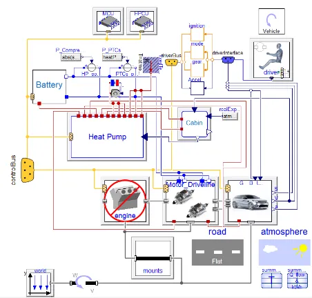
The vehicle being modelled is a2500kg passenger vehicle with a90kWh battery, which is comparable to the Tesla model X [25]. A top level view of the model can be seen in figure 1.
Lumped thermal models are used for all components and have the general equation
mcompCcomp
dTcomp
dt =Qcomp (2)
where the subscript comp refers to any component being
Fig. 1: A top level view of the Dymola model with all relevant submodels.
exterior surfaces. The heat pump can extract heat from ambient which is modelled as an infinite capacity heat sink, from which the evaporator extracts heat through a thermal resistor. The heat pump may also extract heat from the thermal battery, this heat transfer is also modelled using a thermal resistor. The thermal battery needs to encompass the phase change and the latent heat stored. As such its specific heat capacity is a function of temperature and a large spike in specific heat capacity is used to represent the latent heat of melting. This is achieved by increasing the specific heat capacity from
2.20kJkg−1K−1 to169kJkg−1K−1in the temperature interval
75-76◦C. Although in the work of Ukrainczyk et al. [26] it was shown that the latent heat is released over a temperature range, for simplicity it has been assumed that the latent heat is released over a 1◦C interval, the same assumption was made in the thermal battery sizing work of Taylor et al.[27].
B. Test Routine
Some baseline tests were conducted, against which the optimised thermal battery will be compared. Two drive cycles will also be used to compare the results. Firstly the initial testing scenarios were run on a World harmonized Light vehicle Test Procedure (WLTP) test profile, as this is in-line with standard testing procedure. The second cycle is a non standardised 5400 second warm up cycle, with a focus on steady state operation. Tests on the WLTP will be carried out at 23◦C, 14◦C and −7◦C. These temperatures are currently used in WLTP and New European Drive Cycle (NEDC) (the NEDC cycle will not be tested) testing and will give a good comparison of the energy required for a cold start compared to normal operating conditions [28]. One criticism of heat pump technology is the power consumption during its warm up phase. Since the WLTP is the shorter (1800s compared to5400s) of the two test cycles being used, it should help to
TABLE I: Thermophysical properties of Paraffin 70-75, the PCM selcted to for optimal sizing.
Parameter Value
Material Paraffin 70-75
Melting Point 75◦C
Specific heat (solid) 2.06kJ kg−1 K−1 Specific heat (liquid) 2.34kJ kg−1 K−1 Latent heat 169 kJ kg−1
identify the benefits of using a thermal battery to reduce warm up time and power consumption of the heat pump.
The second drive (Warm Up) cycle used focuses more on steady state warm up and power consumption. It consists of
30 minute cruises at 50km/h followed 100km/h and the 30
minutes at rest. The Warm Up cycle is simulated over a larger range of temperatures to get a broader understanding of the heat pump and thermal battery performance. The temperature range used is−20◦C to 10◦C with 2◦C intervals. −7◦C and
14◦C were also simulated so that energy consumption between
the two cycles could be directly compared.
Four different tests were performed before optimising the parameters of the thermal battery. The cycles were first tested using only the PTC heater, this gives baseline results repre-sentative of current electric vehicle heating technology. Next the heat pump was turned on and used in its most basic mode, extracting heat from ambient air; this is the current state of heat pumps on production vehicles such as the Nissan Leaf and BMW i3 [18], [19]. Next the heat battery was introduced and tested with the heat pump. Finally the heat pump and thermal battery were run without the aid of the PTC heaters. This is intended to show that the use of PTC heaters can be negated by the inclusion of a thermal battery. These results produce a baseline before the optimisation procedure takes place. As such some initial parameters were needed to be defined for the thermal battery, this was done by taking a representative example of a thermal battery from literature. The optimisation was then performed and results are given in section III.
C. Optimisation
A specific PCM has been chosen for use in the thermal battery based on work done by Ukrainczyk et al. [26]. The material chosen is Paraffin 70-75, a material sample which Ukrainczyket al.characterise in their work. The specifications of this paraffin are given in table I.
For the optimisation the design parameters will be;
• Mass
• Thermal power (How much heat (kW) can be extracted)
• Initial temperature
Due to the nature of the problem there is no well known equation for the energy consumption, and its value must be obtained by running the model and processing the resulting data. Hence an indirect search algorithm, which requires the use and existence of1st and sometimes2nd order derivatives
[image:4.612.344.529.75.151.2]parameter space and return an optimum design. For the mass and thermal power, the mesh was set to find energy consump-tion at1kg and1kW intervals between1kg and30kg, and1kW and 20kW, respectively. To reduce the number of iterations needed to perform the mesh, only4charge temperatures have been used, 40◦C,70◦C, 100◦C and 140◦C. The upper limits for the search are based on previous studies from literature. The mass and charge temperature are in line with the largest values seen in literature [22], [29]. The maximum power was chosen to exceed 16.5kW, which was the maximum heating capacity of the PTC and heat pump used in this model. It was expected that at this power the heat battery will be able to provide sufficient thermal performance to replace the PTC heater.
An initial set of parameters for the thermal battery was devised to get baseline test results. The mass was chosen to be
10kg, thermal power 6.5kW and 140◦C starting temperature. The maximum temperature was chosen to minimise the mass needed. The mass was then chosen so that the stored energy was equivalent to 1.39kWh, which just exceeds the energy used by the PTC heater during a 20 minute warm up period. The thermal power was chosen to be in-line with the maximum value seen in literature [22].
III. RESULTS AND DISCUSSION
The mesh search to find the optimum design parameters for the heat battery gave the following results, 30kg mass,
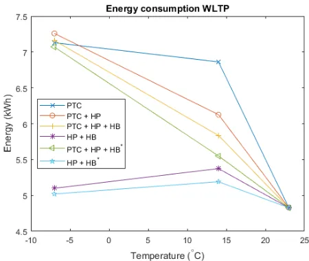
16kW of thermal power and 140◦C initial temperature. The optimum heat battery was subjected to the tests described in section II-B. The energy usage from the WLTP cycle and the Warm Up cycle are shown for different operational modes in figure 2. Here HP refers to the heat pump and HB refers to the baseline heat battery while HB∗ refers to the optimised heat battery.
Across the warm up cycle, seen in figure 2b, PTC+HP+HB∗ and HP+HB∗ give an average energy saving of 12.1% and
25.3% respectively, with peak savings of 21.5% and 27.6% when compared to PTC only. It is also noticable that the best performance gains are found in the region −10◦C, with an average energy saving of 16.8% and 23.8% when comparing PTC+HP+HB∗ and HP+HB∗ to PTC only in this region. Below this temperature the heat pump is unable to extract energy from the ambient. There are 2 significant consequences to this, firstly the cabin heater becomes more dependant on the PTC heater, secondly, the heat pump no longer draws power. The second consequence explains why convergence can be seen between PTC and PTC+HP, and why the vehicle energy consumption reduces as ambient approaches −10◦C for HP+HB and HP+HB∗.
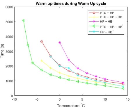
To evaluate whether using a heat battery can effectively replace a PTC heater the time to cabin target temperature (22◦C) was considered. A comparison of warm up times is given in figure 3. Here 5 of the 6 operational modes are shown, as the PTC only configuration was unable to reach cabin target temperature under any ambient condition. It can be seen that PTC+HP+HB∗was the best performer in terms of cabin warm
(a) The total vehicle energy used to complete the WLTP test cycle at −7◦C,14◦C and23◦C is shown for the different operational modes. At 23◦C heating is not required hence the energy usage for all operational modes converges
[image:5.612.323.548.53.243.2](b) The total vehicle energy used to complete the Warm Up test cycle at−20◦C to14◦C is shown for the different operational modes.
Fig. 2: Vehicle energy consumption on WLTP and Warm Up drive cycles.
up time. It is also significant that HP+HB∗ performs almost equivalently to PTC+HP.
Fig. 3: The time taken for the cabin to reach 22◦C. HB
and HB∗ denote the first approximation and optimised heat batteries respectively.
IV. CONCLUSION
It has been shown that the inclusion of a thermal battery into an ambient source heat pump system can reduce vehicle energy consumption over a drive cycle by up to 27.6% under certain conditions. It was also shown that using an optimised thermal battery could make an effective replacement for a PTC heater above −4◦C. However, continuing to use a PTC heater, as in PTC+HP+HB*, allows for a significant energy reduction at moderate temperatures while improving the warm up performance of the system at low temepratures. Further work should be carried out on PTC control to moderate the gap in energy consuption between PTC+HP+HB∗ and HP+HB∗ while maintaing acceptable levels of warm up performance. In Summary, an optimised thermal battery can greatly reduce the dependancy on a PTC heater, but given the limitations at extremely low temperatures, it is not able to completely replace it when designing a vehicle.
ACKNOWLEDGEMENT
This project has been made possible thanks to funding provided by EPSRC, funding and support from Jaguar Land Rover, and software and modelling support from Claytex Services ltd.
REFERENCES [1] https://www.technologyreview.com/s/522496/
electric-vehicles-out-in-the-cold/, accessed: 15/09/2016.
[2] N. Meyer, I. Whittal, M. Christenson, A. Loiselle-Lapointe, The impact of the driving cycle and climate on electrical consumption and range of fully electric passengers vehicles, in: Proceedings of EVS, Vol. 26, 2012.
[3] J. R. M. D. Reyes, R. V. Parsons, R. Hoemsen, Winter happens: the effect of ambient temperature on the travel range of electric vehicles. [4] J. Jaguemont, L. Boulon, Y. Dub´e, D. Poudrier, Low temperature
discharge cycle tests for a lithium ion cell, in: 2014 IEEE Vehicle Power and Propulsion Conference (VPPC), IEEE, 2014, pp. 1–6.
[5] Y. Ji, Y. Zhang, C.-Y. Wang, Li-ion cell operation at low temperatures, Journal of The Electrochemical Society 160 (4) (2013) A636–A649.
[6] Dow Kokam, Superior Lithium Polymer Cell: Technical Data Sheet (9 2010).
[7] F. Zheng, J. Jiang, B. Sun, W. Zhang, M. Pecht, Temperature dependent power capability estimation of lithium-ion batteries for hybrid electric vehicles, Energy 113 (2016) 64–75.
[8] H.-M. Cho, W.-S. Choi, J.-Y. Go, S.-E. Bae, H.-C. Shin, A study on time-dependent low temperature power performance of a lithium-ion battery, Journal of Power Sources 198 (2012) 273–280.
[9] D. Diemand, Automotive batteries at low temperatures., Tech. rep., DTIC Document (1991).
[10] M. Petzl, M. Kasper, M. A. Danzer, Lithium plating in a commercial lithium-ion battery–a low-temperature aging study, Journal of Power Sources 275 (2015) 799–807.
[11] S. Saxena, C. Le Floch, J. MacDonald, S. Moura, Quantifying ev battery end-of-life through analysis of travel needs with vehicle powertrain models, Journal of Power Sources 282 (2015) 265–276.
[12] M. Safari, C. Delacourt, Aging of a commercial graphite/lifepo4 cell, Journal of The Electrochemical Society 158 (10) (2011) A1123–A1135. [13] J. Jaguemont, L. Boulon, P. Venet, Y. Dub, A. Sari, Low temperature aging tests for lithium-ion batteries, 24th IEEE International Symposium on Industrial Electronics (2015) 1–6.
[14] B. Torregrosa-Jaime, J. Pay, J. Corberan, Design of efficient air-conditioning systems for electric vehicles, SAE International Journal of Alternative Powertrains 2 (2) (2013) 291–303.
URL http://www.scopus.com/inward/record.url?eid=2-s2. 0-84881170411&partnerID=tZOtx3y1
[15] H. Helms, M. Pehnt, U. Lambrecht, A. Liebich, Electric vehicle and plug-in hybrid energy efficiency and life cycle emissions, in: 18th International Symposium Transport and Air Pollution, Session, Vol. 3, 2010, p. 113.
[16] M. De Gennaro, E. Paffumi, G. Martini, U. Manfredi, H. Scholz, H. Lacher, H. Kuehnelt, D. Simic, Experimental investigation of the energy efficiency of an electric vehicle in different driving conditions, Tech. rep., SAE Technical Paper (2014).
[17] D. Leighton, Combined fluid loop thermal management for electric drive vehicle range improvement, SAE International Journal of Passenger Cars-Mechanical Systems 8 (2015-01-1709).
[18] http://www.nissan-global.com/EN/TECHNOLOGY/OVERVIEW/heat pump cabin heater.html, accessed: 21/04/2017.
[19] http://www.bmw.co.uk/en GB/new-vehicles/bmw-i/i3/2016/ range-charging.html, accessed: 21/04/2017.
[20] K. Kim, S. Kim, M. Kim, Experimental studies on the heating perfor-mance of the ptc heater and heat pump combined system in fuel cells and electric vehicles, International Journal of Automotive Technology 13 (6) (2012) 971–977.
[21] A. Sharma, V. Tyagi, C. Chen, D. Buddhi, Review on thermal energy storage with phase change materials and applications, Renewable and Sustainable energy reviews 13 (2) (2009) 318–345.
[22] T. J. LaClair, Z. Gao, O. Abdelaziz, M. Wang, E. WolfeIV, T. Craig, Thermal storage system for electric vehicle cabin heating component and system analysis, Tech. rep., Oak Ridge National Laboratory (ORNL), Oak Ridge, TN (United States). Building Technologies Research and Integration Center (BTRIC); National Transportation Research Center (NTRC) (2016).
[23] K. Kaygusuz, Performance of solar-assisted heat-pump systems, Applied Energy 51 (2) (1995) 93–109.
[24] A. Picarelli, V. Avila, S. Robinson, Thermal management strategies for integrated hybrid vehicle subsystems.
[25] https://www.tesla.com/support/model-x-specifications?redirect=no, ac-cessed: 18/04/2017.
[26] N. Ukrainczyk, S. Kurajica, J. ˇSipuˇsi´c, Thermophysical comparison of five commercial paraffin waxes as latent heat storage materials, Chemical and biochemical engineering quarterly 24 (2) (2010) 129–137. [27] R. A. Taylor, C.-Y. Chung, K. Morrison, E. R. Hawkes, Analysis and
testing of a portable thermal battery, Journal of Thermal Science and Engineering Applications 6 (3) (2014) 031004.
[28] P. Mock, J. K¨uhlwein, U. Tietge, V. Franco, A. Bandivadekar, J. German, The wltp: How a new test procedure for cars will affect fuel consumption values in the eu, International Council on Clean Transportation. [29] I. Gritsuk, Y. Gutarevych, V. Mateichyk, V. Volkov, Improving the