© 2019, IRJET | Impact Factor value: 7.211 | ISO 9001:2008 Certified Journal
| Page 416
COST COMPARISON OF DIFFERENT GRID PATTERNS OF FLOOR SLAB OF
SAME SPAN
Ritesh Meshram
1, Prof. Kuldeep Dabhekar
2, Er. Aashish Soni
31
M.Tesh Student (Structural Engineering, GHRCE Nagpur, India)
2
Assistant Professor (Department of Civil Engineering, GHRCE Nagpur, India)
---***---Abstract -A grid is a planar structural system composed of continuous members that either intersect or cross each other .Grids are used to cover large column free areas. Grids in addition provide aesthetically pleasing appearance to the roofs. These slabs are most preferred for public assembly halls, theatres, marriage halls, etc as it covers large column free area. This type of structure is monolithic and has more stiffness. It is beneficial over normal beams as it has a better load dispersing mechanism and also this system reduces the normal span to depth ratio which helps in reducing the height of the building. It has been constructed in number of areas in India n abroad. In the present study we have considered two types of grid patterns, first is two way grid pattern and second is diagonal grid pattern. The structure is analysed and designed with the help of staad pro software. Design has been checked with respect to IS 456-2000 code.
Key Words: Grids, STAAD PRO, IS 456-2000 Code, Span to depth ratio, monolithic, stiffness.
1.INTRODUCTION
As we know in India, the structural cost of work is increases time to time due to increase in material & labor cost, which ultimately lead to increase the total cost of building. The structural cost of work is approximately 50% of the total cost of the building. So it is very essential to reduce the structural cost of building. It can be possible by providing safe & economical grid pattern of floors of building. In India it is popular structural configuration often deployed in the construction of hotel porticos, airport terminal buildings, large banquet hall, convention centres and car parks. The rectangular or square voids that are formed in the ceiling is advantageously utilized for concealed architectural lighting. The sizes of beams running in perpendicular directions are generally kept the same. Instead of rectangular beam grid, a diagonal.
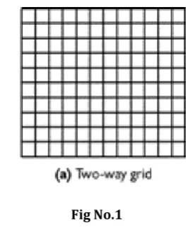
1.1 TWO WAY GRIDS:
In two way grid pattern of floor slab the beams are of similar sizes and they intersect each other in both directions and also they are at equally spaced intervals. These structures
[image:1.595.365.497.276.439.2]are rigid planar oten monolithic structures that disperse loads in multi directional pattern, with the loads generally following the shortest stiffest routes to the supports.
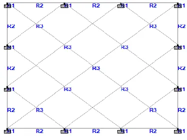
Fig No.1 1.2 DIAGONAL GRIDS
The construction of egg crate is also not as efficient as diagonal grid system. These grids intersect beams diagonally but they are perpendicular to each other. It is required to support the grid at four points only. The diagonal grid has greater torsional rigidity. The sizes of grid beams are normally similar and are also equally spaced.
© 2019, IRJET | Impact Factor value: 7.211 | ISO 9001:2008 Certified Journal
| Page 417
2. METHODOLOGY
In this study we have considered three different grid patterns of beams on a floor slab of same area of 12 x 12m span. The grid that we have used are Two way grids and Diagonal. Second step is we have prepared the Models of the all the grid patterns that we have consisdered using STAAD- PRO V8i software. Model is also checked as per checks available in the software. Third step is analysis and design of the structure using STAAD- PRO V8i software. The design is also manually checked and verified as per IS 456- 2000 code for RCC design. The steps for analysis are given as follows,
a) To apply self weight of the structure in the software. b) To find shear force of the members.
c) To find Bending moments of the members. d) To find the Displacements of the members.
Fourth step is to estimate the quantity of steel and concrete required for all three structures manually. Final step is to find the Structural cost of the building and respectively find the per square feet cost of the building in terms of structural cost.
A. Grid Patterns:-
Grid A (Two way grid) Columns:
R1- 300x600 mm
R3- 300x300 mm
Beams:
R3- 300x750 mm
R4- 230x400 mm
Fig No.5 PATTERN 1
Grid B ( Diagonal grid) Columns:
R1- 400x400 mm
Beams:
R2- 230x450 mm
R3- 300x600 mm
R4- 300x600 mm
[image:2.595.337.525.281.421.2]R5- 300x600 mm
Fig No.6 PATTERN 2
3. LOAD CALCULATIONS
TWO WAY GRID:
DEAD LOADS (IS 875 PART-1)
Dead loads are loads that are permanent on the structure such as construction materials and the materials which are kept permanent on the structure. Also self weight of the structure is considered as dead load.
Self weight :- Selft weight load- Direction Y- Factor = -1
Wall loads:-
Thickness of wall = 230 mm
Floor to floor height = 4m
Height of wall = 3.6m
Load calculation = 0.23 x 20 x 3.6
© 2019, IRJET | Impact Factor value: 7.211 | ISO 9001:2008 Certified Journal
| Page 418
Slab weight calculations :-
Thickness of slab = 125mm
Density of concrete = 25kN/cu.m
Self weight of slab = 0.125 x 25 = 3.125 kN/sq.m
Floor finish = 1.5 kN/sq.m
Total slab weight at floor level = 3.125+1.5= 4.625 kN/sq.m
LIVE LOADS (IS 875 PART 2)
Live loads are produced due to use and occupancy of building. These are normally due to human occupants, storage, furnishings, etc.
Live Load intensity specified = 4 kN/sq.m
LOAD COMBINATIONS:
Type L/C Name
Primary 1 DL
Primary 2 LL
Combinations 3 1.5(DL+LL)
DIAGONAL GRIDS :
Wall loads:-
Thickness of wall = 230 mm
Floor to floor height = 4m
Height of wall = 3.55m
Load calculation = 0.23 x 20 x 3.55
= 16.33 kN/m
Slab weight calculations :-
Thickness of slab = 125mm
Density of concrete = 25kN/cu.m
Self weight of slab = 0.125 x 25 = 3.125 kN/sq.m
Floor finish = 1.5 kN/sq.m
Total slab weight at floor level = 3.125+1.5= 4.625 kN/sq.m
LIVE LOADS (IS 875 PART 2)
Live loads are produced due to use and occupancy of building. These are normally due to human occupants, storage, furnishings, etc.
Live Load intensity specified = 4 kN/sq.m
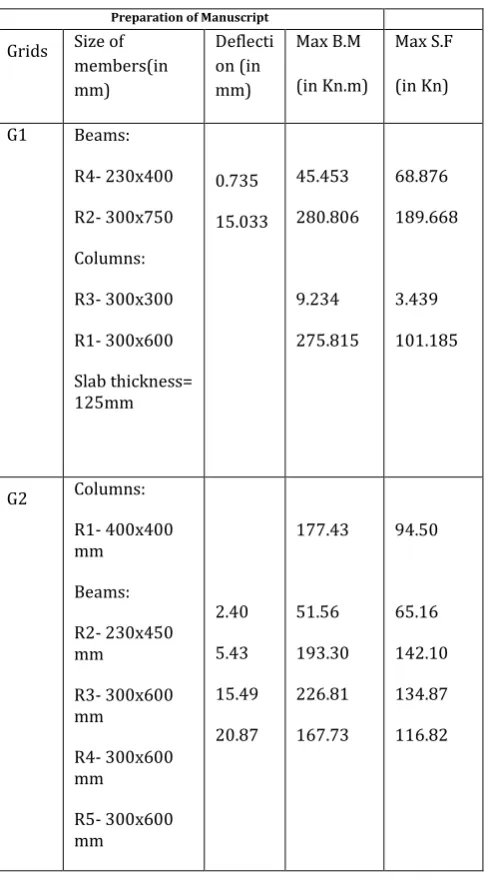
[image:3.595.323.566.253.695.2]4. ANALYSIS AS PER STAAD PRO
Table -1: Sample Table format Preparation of Manuscript
Grids Size of members(in mm)
Deflecti on (in mm)
Max B.M
(in Kn.m)
Max S.F
(in Kn)
G1 Beams:
R4- 230x400
R2- 300x750
Columns:
R3- 300x300
R1- 300x600
Slab thickness= 125mm
0.735
15.033
45.453
280.806
9.234
275.815
68.876
189.668
3.439
101.185
G2 Columns: R1- 400x400 mm
Beams:
R2- 230x450 mm
R3- 300x600 mm
R4- 300x600 mm
R5- 300x600 mm
2.40
5.43
15.49
20.87
177.43
51.56
193.30
226.81
167.73
94.50
65.16
142.10
134.87
© 2019, IRJET | Impact Factor value: 7.211 | ISO 9001:2008 Certified Journal
| Page 419
5. DESIGN
DESIGN PARAMETERS:
As per IS 456-2000 code these design parameters has been set in STAAD PRO V8i software.
a) Brace: Beam/Column braced in both directions b) Clear cover: for column = 40mm
for beam = 30 mm
c) Ely: Min length factor about local Y direction = 1 d) Elz: Min length factor about local Y direction = 1 e) Fc: compressive strength of concrete = 25 N/sq.mm f) Fy main: 500 N/sq.mm
g) Fy sec: 500 N/sq.mm h) Max main: 32mm i) Min main: 12mm j) Max sec: 10mm k) Min sec: 8mm
l) Ratio: Max percentage of longitudinal reinforcement allowed = 4
m) R face: Longitudinal reinforcement in column along four faces
n) Torsion: Design for torsion
o)
Track: Beam and column minimum details
are printed
p)
Commands: Design Beam, Design column.
Two way grid pattern (G1)
Column design:
Beam design:
2)
Diagonal grid pattern (G2):
Schedule of beams:
Schedule of columns:
Schedule of slabs:
6. ESTIMATION
Grid A: CONCRETE QUANTITY
:
Size of members No. L (m) B(m)
D (m) Qty (cu.m)
Beams
R2(300x750mm)
6
11.40
0.30
0.625 12.825
R4(230x400mm) 16 10.5 0.23 0.275 10.626
© 2019, IRJET | Impact Factor value: 7.211 | ISO 9001:2008 Certified Journal
| Page 420
R3(300x300mm) 4 3.6 0.3 0.3 1.296R1(300x600mm) 12 3.6 0.3 0.6 7.776
Slab 1 10.5 10.5 0.125 13.78
Deductions 9 0.3 0.625 1.685
Total qty 44.618
REINFORCEMENT QUANTITY:
FOR COLUMN:
Description Dia No. L(m) wt/m Qty (kg)
C1 12 8 4 0.89 28.48
C2 12
16 6
6
4
4
0.89
1.58
21.36
37.92
Lateral ties 8 28 1.040 0.395 11.50
Total 99.26
FOR BEAMS:
For R4: 230x400 mm
Description Dia No. L(m) wt/m Qty (kg) Total Qty(kg)
Bott. Bars 12 2 13.20 0.89 23.49 93.98
Cut at middle
2/3*L
12 1 8 0.89 7.12 28.48
Top bars 12 2 13.20 0.89 23.49 93.98
Extra top 12 1 7.2 0.89 6.408 25.632
Stirrups 8 80 1.112 0.395 35.14
Total 277.212
For R2: 300x750 mm
Descripti on
Di a
No .
L(m) wt /m
Qty (kg) Total Qty(k g)
Bott Bars
25 3 14.5 3.8 5
55.94x3=16 7.82
1006. 92
Cut at middle
2/3*L
25 3 8 3.8
5
30.8x3=92.4 554.4
Top bars 25 2 14.5 3.8 5
55.94x3=16 7.82
1006. 92
Extra top
25 3 3.6 3.8 5
13.86x3= 41.58
249.4 8
Stirrups 8 12 0
1.96 0
0.3 95
92.91
Total 2910
For slab:
No. of bars required = 22
Straight bars = 11
Bent up bars = 11
Cutting length of bent up bars = L + 0.42H + Ld – bends
Here, H = D – (2 x clear cover) – diameter of bar
= 125 – (2 x 20) – 8 = 77
Cutting length of bent up bars = 3.34 m
Cutting length of straight bars = L + Ld
= 3000 + (45 x 8)
= 3.36 m
Distribution reinforcement:
No. of bars required = 22
Extra reinforcement = 8
© 2019, IRJET | Impact Factor value: 7.211 | ISO 9001:2008 Certified Journal
| Page 421
= 3000 – (2 x 900) + 300= 1.5 m
Description Dia No. L(m) wt/m Qty (kg)
Total Qty(kg)
Bent up bar 8 11 3.34 0.3950 14.51
Straight bars 8 11 3.36 0.3950 14.6
Distribution reinforcement
8 22 3.36 0.3950 29.19
Extra reinforcement
8 8 1.5 0.3950 4.74
Summation 63.04
x 2
126.08
Total 2017.28
TOTAL QUANTITY OF STEEL = 5303 kg
Grid G2 : CONCRETE QUANTITY
Beam(mm) No. L B D Qty.(cu.m)
R2- 230x450
4 12.40 0.23 0.325 3.707
R3- 300x600
4 5.65 0.3 0.475 3.22
R4- 300x600
4 11.31 0.3 0.475 6.44
R5- 300x600
2 16.97 0.3 0.475 4.83
Slab 1 12.23 12.23 0.125 18.69
Column- 400x400
12 3.55 0.4 0.4 6.816
Total A 43.70 Deductions Junction of beams
R3 & R5 4 0.3 0.3 0.475 0.171
R4 & R4 4 0.3 0.3 0.475 0.171
R4 & R5 4 0.3 0.3 0.475 0.171
R5 & R5 1 0.3 0.3 0.475 0.04275
Total B
0.55
NET QTY. = 43.15 cum
The steel quantities can be calculated as calculated for Grid pattern G1. So here is the quantity estimate of steel of grid pattern G2, Di a Colm. (m) Beam (m) Slab (m) Total (m) Wt (kg/m) Total (kg)
8 20.16 1900 3100 0.395 2142
16 345.60 312 657 1.58 1039
25 528.56 528.56 3.58 1894
32 210.24 210.24 6.320 1328
Total 6403
7. CONCLUSION
COST COMPARISON:
GRID NO. C.C QT Y. RATE 7200/ - Steel QTY. (M.T) RATE Rs.60,000 /M.T Total Amou nt COST PER SQUAR E FEET1 44. 618
3,21,2 49/-
5.303 3,18,180/ -
6,39,4 29/-
4,440/-
2 43. 15
3,10,6 80/-
6.403 3,84,180/ -
6,94,8 60/-
4,825/-
3 47. 90
3,44,8 80/-
6.727 4,03,620/ -
74850 0/-
© 2019, IRJET | Impact Factor value: 7.211 | ISO 9001:2008 Certified Journal
| Page 422
The quantity of concrete required for grid 1 is 44.618 and steel quantity is 5.303 M.T and cost per square feet is 4400/-.
The quantity of concrete required for grid 2 is 43.15 and steel quantity is 6.403 M.T and cost per square feet is 4825/-.
Thus we conclude that TWO WAY GRID PATTERN is
economical cost wise as well as steel and concrete wise as compared to DIAGONAL GRID. But for architectural view purpose some may use Diagonal grid pattern as its aappearance is good as compared to two way grid pattern. Torsional rigidity of Diagonal grid pattern is good as compared to two way grids. There sre several grid patterns that can be used and each grid pattern has different significance on the structure. But they are way good compared to Buildings with no. of columns. Thus, We can cut the structural cost of the building by providing grid patterns of floor slabs.
CONCRETE QTY COMPARISON
STEEL QTY COMPARISON
COST COMPARISON
REFERENCES
Amick, H., Hardash, S., Gillett, P., and Reaveley, R. (1991). “Design of Stiff, Low-Vibration Floor Structures.”
Proceedings of International Society for Optical Engineering (SPIE), 1619,180-191
Das, B. (2010), “Static and Dynamic Analysis of Grid Beams,” thesis, presented to National Institute of Technology Rourkela, in partial fulfillment of the requirements for the award of bachelors of technology degree in civil engineering.
IS 456 (2000). “Indian Standard Plain Reinforced Concrete Code of Practice”, Fourth Revision, Bureau of Indian Standards (BIS), New Delhi.
IS 875 (1987). “Indian Standard Code of Practice for Design Loads (Other Than Earthquakes) For Building and Structures Part 2: Imposed Loads”, Second Revision,
Bureau of Indian Standards (BIS), New Delhi.
Ozturk, T., and Ozturk, Z. (2008). “The effects of the type of slab on structural system in the multi storey reinforced concrete buildings.” Proceedings of the 14th
World Conference on Earthquake Engineering, Beijing, China, October 12-17.
Patel, H., and Vepari, I. (2011). “Study on economical aspects of long span slabs.” National Conference on Recent Trends in Engineering and Technology, B.V.M. Engineering College, V.V. Nagar, Gujarat, India, May 13-14.
Sathawane, A., and Deotale, R. (2011). “Analysis and Design of Flat Slab and Grid Slab and their cost comparison.” International Journal of Engineering Research and Applications, 1, 837-848.