This paper is made available online in accordance with
publisher policies. Please scroll down to view the document
itself. Please refer to the repository record for this item and our
policy information available from the repository home page for
further information.
To see the final version of this paper please visit the publisher’s website.
Access to the published version may require a subscription.
Author(s): T. Huang , H.T. Liu and D.G. Chetwynd
Article Title: A Method to Formulate a Dimensionally Homogeneous
Jacobian of Parallel Manipulators
Year of publication: 2011
Link to published article:
http://dx.doi.org/10.1109/TRO.2010.2082091
Publisher statement: “© 2011 IEEE. Personal use of this material is
permitted. Permission from IEEE must be obtained for all other uses, in
any current or future media, including reprinting/republishing this
material for advertising or promotional purposes, creating new
collective works, for resale or redistribution to servers or lists, or reuse
of any copyrighted component of this work in other works.”
Citation: Huang, T. et al. (2011). A Method to Formulate a
Abstract—This paper presents a general and systematic approach for formulating the dimensionally homogeneous Jacobian, an important issue for the dexterity evaluation and dimensional synthesis of f-DOF (f ≤6) parallel manipulators having mixed rotational and translational movement capabilities. Utilizing f independent coordinates to describe the specified motion types of the platform, the f×f dimensionally homogeneous Jacobian is derived directly from the generalized Jacobian provided that the manipulator has only one type of actuator. The condition number of the new Jacobian is then employed to evaluate the dexterity of two typical 3-DOF parallel manipulators as an illustration of the effectiveness of this approach.
Index Terms—Parallel manipulators, dimensionally homogeneous Jacobian
I. INTRODUCTION
he Jacobian, conventionally defined as the linear map between actuator rates in the joint space and velocity twist in the operation space, plays an important role in kinematic performance evaluation and optimization of manipulators having different architectures. For those manipulators having coupled translational and rotational movement capabilities, it has been recognized that the algebraic characteristics such as condition number, maximum/minimum singular values, etc. of the Jacobian vary with the scaling due to the inconsistency in physical units of its terms. This may cause a serious problem [1-3] when they are employed as the conditioning indices in kinematic performance evaluation and design optimization. Therefore, it is critically important to formulate dimensionally homogeneous Jacobians in which all entries have the same physical units.
A review of the existing literature shows that two methods might be employed to formulate a dimensionally homogeneous
Manuscript received December 1, 2010. This research work is partially supported by the National Natural Science Foundation of China (NSFC) under grants 50535010 and 50775158.
H. Liu is with the School of Mechanical Engineering, Tianjin University, Tianjin 300072, China (e-mail: [email protected]).
T. Huang is with the School of Mechanical Engineering, Tianjin University, Tianjin 300072, China (phone: +86 22 27405280; fax: +86 22 27405280; e-mail: [email protected]). He is also partially with the University of Warwick, Coventry CV4 7AL, UK. ([email protected])
D. G. Chetwynd is with the School of Engineering, University of Warwick, Coventry CV4 7AL, UK. (e-mail: [email protected]).
Jacobian. One way is the length-based method that adopts a “characteristic/natural length” to normalize all translational elements in the Jacobian subject to isotropic constraints [4-10]. Design optimizations are then based on the condition number of the dimensionally homogeneous Jacobian being minimized. This method is suited to the design of an isotropic manipulator because the characteristic/natural length varies with the system configurations. A more practical approach is to use the point-based method to achieve a dimensionally homogeneous Jacobian by linking the actuator rates with the linear velocities at several points on the end-effector provided that all actuators are of identical type. Research along this track can be traced back to the early work [11] dealing with the optimum design problem of planar and spatial serial manipulators. The idea was then extended to 6-DOF parallel manipulators, resulting in a
6 9 dimensionally homogeneous Jacobian [12-14]. More recently, using a 3-PRS or 3-RPS mechanism as an example, the point-based method was taken further to formulate the f f
dimensionally homogeneous Jacobian of f-DOF parallel manipulators [15, 16]. However, this method suffers from a rather heavy computational burden as partial derivatives have to be established on a case-by-case basis.
Drawing on the needs for kinematic performance evaluation and optimization, this paper presents a general and systematic computational approach for obtaining the f f dimensionally homogeneous Jacobian of f-DOF parallel manipulators(f 6). The method is implemented in two steps: (1) formulating the linear map between the joint rates and velocity twist using the generalized Jacobian [17]; (2) generating a linear map between the velocity twist and f linear velocities at a set of selected points on the end-effector provided that the manipulator has only one type of actuator. On the basis of this new Jacobian, a condition number is then used to evaluate the dexterity of two 3-DOF parallel manipulators having coupled translational and rotational motion capabilities.
II. FORMULATION OF THE GENERALIZED JACOBIAN This section briefly reviews the formulation process of the generalized Jacobian [17] of a parallel manipulator having f-DOF (2 f 6). Without loss of generality, assume that the manipulator is composed of l ( f l f 1) limbs connecting the platform with the base, each essentially containing ni
A method to formulate a dimensionally
homogeneous Jacobian of parallel manipulators
Haitao Liu, Tian Huang, and Derek G Chetwynd
account. The first family covers fully parallel manipulators having f constrained active limbs (ni 6 for all limbs). The second family comprises those having f unconstrained active limbs (i.e. ni 6 for each of these f limbs) plus one properly constrained passive limb. For convenience, the properly constrained passive limb is always designated byl f 1. Any other parallel manipulators not belonging to these two families can be dealt with in a manner similar to that used below.
On the one hand, the set of continuous motions of the platform forms a Lie group SE(3) [18].
3
SE 3 SO 3 , 4,
0 1 GL
R r
R r (1)
where ris the position vector of the origin of the platform in the fixed body frame R0 and R is the orientation matrix of
0
R with respect to the reference frame R . At any point in SE(3), the Lie algebra of SE(3) is a 6-dimentional vector space and can be expressed as
3
se 3 so 3 ,
0 0
α r
α r (2)
where δr is the variation of r and δα is a skew-symmetric matrix with its entries representing the angular variation of the platform. Note that se(3) has a “variational” rather than “differential” structure of SE(3) so as to encompass a broader sense of the first order kinematics in terms of velocity, pose error and deflection. Note that se(3) is isomorphic to 6 via the mapping
T
T T 6
0 0 t
δ δ
δ δ
α r
r α
$ (3)
Since $t has a form of twist in screw theory and thus se(3) is referred to as the twist space, denoted T for symbolic consistency in the later use.
On the other hand, the set of wrenches exerted on the platform forms a 6-dimensional vector space W known as the wrench space with $w fT τT T being its elements, where
f and τ are the applied force and moment exerted on the platform. T andW are a pair of dual spaces known as the tangent space and cotangent space of SE(3), respectively [18]
It has been shown [17] that for an f-DOF parallel manipulator, T can uniquely be decomposed into a pair of complementary subspaces, i.e., an f dimensional subspace Ta and a 6-f dimensional subspaceTc , associated respectively with the permitted and restricted instantaneous motions of the platform, and thus known as the twist subspaces of permissions and restrictions. Correspondingly,W can be decomposed into a
a c
with actuation and constraint wrenches exerted on the platform by the limbs, and thus known as the wrench subspaces of actuations and constraints.
Note that $t and $w are expressed in the form of axis- coordinate and ray-coordinate, the virtual work done by $won
t
$ can be represented by the inner product that is equivalent to the reciprocal product defined in screw theory [20-22].
, = , +
, , , ,
w t wa wc ta tc
wa ta wc tc wa tc wc ta
δW $ $ $ $ $ $
$ $ $ $ $ $ $ $ (4)
It has been proved [17] that $wa,$tc $wc,$ta 0 ,
,
wa ta δa
$ $ and $wc,$tc δc as $wa ($wc) does not do work on $tc ($ta), and $wa ($wc) does work on $ta ($tc). Thus, the following relationships hold:
Orthogonality: Wa Tc , Wc Ta (5a)
Duality: Wa Ta*, Wc Tc* (5b)
Let ˆ , , , a ta j i a i
$ T , ˆ , , , a wa k i a i
$ W (j ka, a 1,2, ,ni) and ˆ , , , c tc j i c i
$ T ,
, , ,
ˆ c wc k i c i
$ W (j kc, c 1,2, ,6 ni) be the basis elements of the four vector subspaces associated with the ith limb. The twist of the platform can then be represented by a linear combination of the basis elements of Ta i, and Tc i, (i 1, 2, ,l)because all limbs share the same platform
, ,
6
, , , , , , , ,
1 1
ˆ ˆ
i i
a a c c
a c
t ta tc ta i tc i
n n
a j i ta j i c j i tc j i
j j
δρ δρ
$ $ $ $ $
$ $ (6)
where $ˆta j i,a, and δρa j i,a, ($ˆtc j i, ,c and δρc j i, ,c ) are the jath (jcth) unit screw of permissions (restrictions) and its intensity. In screw theory, ˆ , ,
a
ta j i
$ is none other than the unit screw of the
th
a
j 1-DOF joint within the ith limb having connectivity of
6
i
n [22].
In velocity analysis where merely the ideal motions of the platform are considered, it gives $t $ta vT ωT T ,
,a, ,a, a j i a j i
δρ q and , , 0
c
c j i
δρ such that
6
, , , , , ,
1 1
ˆ 0 ˆ
i i
a a c
a c
n n
t a j i ta j i tc j i
j j
q
$ $ $ (7)
where v and ω are the linear velocity of the reference point on the platform and angular velocity of the platform, and , ,
a
Let $ˆwa g k, k, be the unit wrench of actuations associated with the actuated joint, which is labelledgkin the kth (k 1, 2, ,f) limb. Note that ˆ , ,
k
wa g k
$ is dual to ˆ , , k ta g k
$ but orthogonal to
, , ˆ
a
ta j k
$ ( ja 1, 2, ,nk , ja gk ) in accordance with the properties given in Eq.(5). Similarly, let ˆ , ,
c
wc k i
$ be the kcth
unit wrench of constraints in the ith limb. Also, note that ˆ , , c
wc k i $
is orthogonal to ˆ , , a
ta j i
$ (ja 1, 2, ,ni). Thus, taking the inner product on both sides of Eq.(7) with ˆ , ,
k wa g k
$ and ˆ , ,
c
wc k i $ , respectively, results in
t
J$ q (8)
a c J J J = ,
1 1 1
2 2 2
T T
, ,1 , ,1 , ,1
T T
, ,2 , .2 , ,2
T T
, , , , , ,
ˆ ˆ ˆ
ˆ ˆ ˆ
ˆ ˆ ˆ
f f f
wa g wa g ta g wa g wa g ta g a
wa g f wa g f ta g f J $ $ $ $ $ $ $ $ $ , ,1 ,2 , c c c c l J J J J T T
,1, ,1, ,1,
T T
,2, ,2, ,2, ,
T T
,6 , ,6 , ,6 ,
ˆ ˆ ˆ
ˆ ˆ ˆ
ˆ ˆ ˆ
i i i
wc i wc i tc i wc i wc i tc i c i
wc n i wc n i tc n i J
$ $ $
$ $ $
$ $ $
, q= qa 0 ,
1
2
, ,1
, ,2
, f, a g a g a
a g f q q
q q
where J is an
1 6 6
l i i
f n matrix known as the
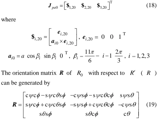
generalized Jacobian of f-DOF parallel manipulators, which has a broader sense than the overall Jacobian developed by other means in the existing literature [23]. With the aid of Eq.(8), the formulation of f f dimensionally homogeneous Jacobian of parallel manipulators will be discussed in next section.
III. FORMULATION OF THE f f DIMENSIONALLY HOMOGENEOUS JACOBIAN
Theoretically, the translations of three non-collinear points on a rigid body are sufficient to uniquely identify the motion of
the body in terms of translation and rotation. Hence, on the basis of the generalized Jacobian given in Eq.(8), a computational scheme to formulate the f f dimensionally homogeneous Jacobians of f-DOF parallel manipulators is proposed as follow.
Firstly, place a reference frame R at a point O on the base and a body fixed frame R0 on the platform at a point O . Also, set an instantaneous reference frame R with its origin at point O while its three orthogonal axes remain parallel to those of R as shown in Fig.1. Secondly, express the velocity
i
v at point Pi on the platform in terms of velocity v at point
O and angular velocity ω of the platform, i.e.
i i
v v ω p (9)
Expressing all vectors in R with pi the position vector pointing from O to Pi, place a set of axes at point Pi and let
, i j
e be the unit vector along the jth such axis. Then, taking the dot product on both sides of Eq.(14) with ei j, leads to
0
T T
, , 0Ad R R i j i j g t
v $ $ (10)
, 0 , 0
0 , 0 i j i j
i i j e p e $ , 0 Ad R R g R R 0 0
where ei j, 0 R eT i j, and
T 0
i i
p R p are the vectors of ei j, and pi evaluated in R0 with R being the orientation matrix of R0 with respect to R ( R ); $i j, 0 is a unit wrench of zero pitch measured in R0 , representing a unit force along
, i j
e at point Pi.
In order to fully describe the different motion types of parallel manipulators having coupled DOF, it is necessary to select a set of appropriate points on the platform and specify the relevant axes along which the dot product is taken. Although taking three distinct and non-collinear points on the platform is sufficient to identify its pose, a practical generic way to do this is to take 5 points as the candidates: e.g., the 4 vertices of a triangular pyramid (tetrahedron) having an equilateral base and
Fig.2. Points and axes arrangements on a tetrahedron
0 O P 3,10 e 1 P 2 P 3 P 4 P
1 e1,10
1,20 e 4,10 e 4,20 e 10 p 3,20 e 2,20 e 2,10 e 30 p 20 p 40 p 0 x 0 y 0 z
Fig.1. Frame settings on the platform
three identical isosceles faces plus the centre of its base for providing axial symmetries and easier implementation. For this arrangement of points, assume that point O is the centre of the base equilateral triangle lying in the x0 y0 plane of R0 , taken to be the plane containing the centres of joints connected with the platform. In this way, it is sufficient to choose two orthogonal axes at each vertex such thatei,10 ei,20, ei,10 pi0 and ei,20 pi0 (i 1,2,3,4) as shown in Fig.2. Thus,
T
,10 sin cos 0
i i i
e , ei,20 0 0 1T
T
0 cos sin 0
i p i i
P , for i 1, 2,3
T
4,10 1 0 0
e , e4,20 0 1 0T, p40 p 0 0 1T
where i is the position angle of pi (i 1, 2,3) lying in thex0 y0 plane; p is the height of the tetrahedron which is equal to the circumscribing radius of the base. And at point O
T
0,10 1 0 0
e , e0,20 0 1 0T, e0,30 0 0 1T
Rewrite Eq.(10) in matrix form
0
T 0Ad R
R
p p g t
v J $ (11)
where
T
0 0,10 0,20 4,20
p
J $ $ $ , vp v0,1 v0,2 v4,2 T
0 p
J is an 11 6 matrix (i.e., two for each ei j, 0 with
1,2,3,4
i , j 1, 2 and three more for e0, 0j with j 1, 2, 3). For an f-DOF parallel manipulator with a specified motion type,
any f linearly independent row vectors of Jp0 can be selected to form an f 6 matrix Jpa0 . Thus, the linear map
6
: t pa f
L $ v can be obtained
pa pa a J v q ,
0
1 1
T T T
0Ad R R
pa pa g a
J J J J J (12)
where Jpa is an f f matrix known as the dimensionally homogeneous Jacobian of f-DOF parallel manipulators. It is easy to see that Jpa0 depends only upon pi0 and ei j, 0 . Therefore, the computational burden to formulate the dimensionally homogeneous Jacobian can be reduced dramatically once the generalized Jacobian has been made available using the approach given in Section II. It should be noted that the choice of f linearly independent row vectors of
0 pa
J is not unique. In order to solve this problem Jpa0can be formulated by either of two ways. By setting p 1 one way is to choose Jpa0 of which the minimum singular value takes the maximum value. Although this is a systematic approach, it is rather time consuming. By utilizing the 3-2-1 positioning principle in the jig design, a more straightforward way is to select f $i j, 0that enable to describe the prescribed motion type of the platform, and to achieve the highest feasible degree of axial symmetry. For example, it is very natural to select $0,10,
0,20
$ , $4,10and $4,20 to formulate Jpa0 of a 2R2T parallel manipulator in terms of two translations along and two rotations about the x0 and y0axes. On this basis, Table I enumerates suitable Jpa0 for a number of 3~6 DOF parallel manipulators
Motion types Descriptions Jpa0
3R3T
3 rotations about the x, y and z axes or three axes not consecutively parallel and 3 translations along the x, y and z axes
T 0 1,10 1,20 2,10 2,20 3,10 3,20
pa
J $ $ $ $ $ $
3R2T
3 rotations about the x, y and z axes or three axes not consecutively parallel and 2 translations along the x and y axes
T 0 1,10 2,10 3,10 4,10 4,20
pa
J $ $ $ $ $
2R3T
2 rotations about the x, y axes or two axes not consecutively parallel and
3 translations along the x, y and z axes
T 0 1,20 2,20 3,20 4,10 4,20
pa
J $ $ $ $ $
2R2T
2 rotations about the x and y axes or two axes not consecutively parallel and
2 translations along the x and y axes
T 0 0,10 0,20 4,10 4,20
pa
J $ $ $ $
1R3T 1 rotation about the z axis and 3 translations along the x, y and z axes
T 0 0,30 1,10 2,10 3,10
pa
J $ $ $ $
2R1T
2 rotations about the x and y axis or two axes not consecutively parallel and
1 translation along the z axis
T 0 1,20 2,20 3,20
pa
J $ $ $
1R2T 1 rotation about the z axis and 2 translations along the x and y axes
T 0 1,10 2,10 3,10
pa
J $ $ $
[image:5.612.97.512.74.303.2]having coupled DOF. It can be seen that for each case the selected f linearly dependent wrenches relate to no more than 3 points out of 5 candidates.
There are some 3-DOF non-overconstrained parallel manipulators having coupled DOF for which the dimensionally homogeneous Jacobian can directly be generated if either the translational or the rotational components in$tcan be taken as the independent coordinates. The 3-DOF module within the Tricept robot [24] is a typical example of this condition. For such cases, Eq.(8) is rewritten in a partitioned form as
vv v a
v
J J v q
J J ω 0 (13)
and then if, for example, the linear velocity of point O is taken as the independent coordinates,
pa a
J v q , Jpa Jvv Jv J 1J v (14)
IV.EXAMPLES
The dexterity analyses of two typical parallel mechanisms are carried out using Eq.(12) or (14) developed in Section III to illustrate the effectiveness of the proposed approach.
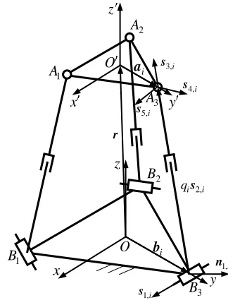
A. 3-RPS parallel mechanism
As shown in Fig.3, the 3-RPS parallel mechanism consists of a base, a platform, and three identical limbs, each connecting the base with the platform in sequence by a revolute joint R, an actuated prismatic joint P, and a spherical joint S. Therefore,
5
i
n (i 1, 2,3). The unit screws of permissions, , a
ta j i,
ˆ $
( ja 1, 2, ,5), in the ith limb can be obtained by
2 1, 1,
1, i i i i ta i
i q , ,
a s s
ˆ
s
$ , ˆ$ta,2,i s2,i
0
3, 3,
3, i i ta i
i
,
a s ˆ
s
$ , 4, 4,
4, i i ta i
i
,
a s ˆ
s
$ , 5, 5,
5, i i ta i
i
,
a s ˆ
s
$ (15)
where , a
j i
s is a unit vector along the jath 1-DOF joint of the ith limb; ai O Ai and qis2,i B Ai i . The joint axes are arranged such that s1,i s2,i; s3,i, s4,iand s5,i are coincident with three rotational axes of the spherical joint, with s3,i s2,i. Utilizing the properties given in Eq.(5) , the unit wrench of constraints (actuations) ˆ$wc i,1, ($ˆwa,2,i) and the unit screw of restrictions $ˆtc i,1, (i 1, 2,3) can sequentially be determined by the observation method [22].
1, ,1,
1, i wc i
i i s ˆ
a s $
2, ,2,
2,
ˆ i
wa i
i i s
a s
$ , ,1, 2, 1,
1,
ˆ i i i i
tc i
i q
a s n
n
$ (16)
where n1,i s2,i s1,i . Substituting Eqs.(19) and (20) into Eq.(8), results in the generalized Jacobian of the 3-RPS mechanism.
a c J J
J
= (17) Table II
DIMENSIONS OF A 3-RPS PARALLEL MECHANISM (UNIT: mm)
a b qi0
250 312.5 540
i
[image:6.612.359.521.146.362.2]O A a; OBi b; qi0 is the initial length of the ith prismatic joint (i=1,2,3).
Fig.3. Schematic diagram of a 3-RPS mechanism
O
x
y
z
y
z
3 B 3 A 2 A
1
A O
2 B
1 B
i a
i b x
2,
i i
qs
1,i
n
4,i
s
3,i
s
5,i
s
1,i
[image:6.612.330.562.402.632.2]s r
Fig.4. Distribution of k(Jpa) of the 3-RPS mechanism
cos
x , y sin
y
θ θx
k
(
Jpa
)
0.5436 m 0.6436 m 0.7436 m z
T T
2 2 2 2 2
T T
2 3 3 2 3
a , ,
, ,
J s a s
s a s
, 1 2T 2 2 1 2 T 2
T T
1 3 3 3 1 3 3
c q q
q q
, ,
, ,
J s a s
s a s
Considering the mechanism to have three degrees of freedom in terms of one translation and two rotations which then produce other parasitic motions, Jpa0 can be formulated by selecting
,2 i
v along the ei,20 at point Pi( Ai) (i 1, 2,3) as the three independent coordinates, i.e.
T 0 1,20 2,20 3,20
pa
J $ $ $ (18)
where
,20 ,20
0 ,20 i i
i i e
a e
$ , ei,20 0 0 1T
T
0 cos sin 0
i a i i
a , 11 1 2
6 3
i i , i 1, 2, 3
The orientation matrix R of R0 with respect to R ( R ) can be generated by
c c s c s c s s c c s s
s c c c s s s c c c c s
s s s c c
R (19)
where , and are three Euler angles of precession, nutation and body rotation, respectively, with ; “s” and “c” denote sine and cosine functions. Thus, substituting Eqs.(17)-(19) into Eq.(12) finally results in a 3 3
dimensionally homogeneous Jacobian Jpa.
As an illustration, consider a 3-RPS parallel mechanism having the geometric parameters given in Table II, a rotational
capability of 40 throughout 0~360 and a
translational capability of 200 mm from z=536.4 mm to z=736.4 mm. Fig.4 plots the condition number of Jpa , Jpa ,
evaluated throughout the entire task workspace. It can be seen that for a given z-coordinate of O, Jpa takes a maximum value at 40 when 0 120 240, , ; its minimum value occurs at 0 . It shows that the kinematic performance can be improved slightly by increasing the distance between O
andO within the given range of the stroke. B. 3-UPS&UP parallel mechanism
Fig.5 shows the schematic diagram of the 3-UPS&UP parallel mechanism which forms the main body of the Tricept robot [24]. The mechanism is composed of three identical unconstrained active UPS limbs and one properly constrained passive UP limb. Each UPS limb connects the base to the platform in sequence by a universal joint, an actuated prismatic
joint, and a spherical joint, while the UP limb connects the base to the platform by a universal joint followed by a prismatic joint. Therefore, ni 6 (i 1, 2,3) for the UPS limb and n4 3for the UP limb.
The bases of four vector subspaces of the ith UPS limb and UP limb are given in an extensive analysis of this system [17], so its generalized Jacobian is easily formulated. For this particular case the three components of the linear velocity, v, of point O can be taken as three independent coordinates.
a b H
120 346.4 805
i
[image:7.612.59.289.51.119.2]O A a; OBi b; qi0 is the initial length of the ith prismatic joint (i=1,2,3).
Fig.5 Schematic diagram of the 3-UPS&UP mechanism within the Tricept robot
i b
2 A
ai 2
B O
O 2,i
s s1,i
2,4
s
3, i i qs
1,4
s
6,i s
5,i s
4,i s
4 3,4 q
r s
x
z y
1 B 3 B
3 A
1 A
x
z y h
H
Fig.6 Distribution of k(Jpa) of the 3-UPS&UP mechanism
x y
k
(
Jpa
)
1.005 m 0.905 m 0.805 m z
[image:7.612.334.561.59.100.2] [image:7.612.45.301.207.404.2]Thus the 3 3 dimensionally homogeneous Jacobian Jpa can
be obtained directly by using Eq.(14).
pa a
J v q , Jpa Jvv Jv J 1J v (20)
T 3 1 T 3 2 T 3 3 vv
,
,
,
s
J s
s
,
T 1 3 1
T 2 3 2
T 3 3 3 v
,
,
,
a s
J a s
a s
T 2 4 T 2 4
v ,
,
J s
n 0
,
T 1 4
T 4 3 4 2 4
T 4 3 4 2 4 q
q ,
, ,
, ,
n
J s s
s n
where ,
a
j i
s (i=1,2,3) is a unit vector along the jath 1-DOF joint of the ith limb. qa q1 q2 q3 T with qi being the rate of the ith actuated UPS limb along s3,i.Here, the joint axes are arranged such that s1,i s2,i, s2,i s3,i, s3,i s4,i, s1,4 s2,4, and s2,4 s3,4. ai O Ai , q4 3 4s , OO , n1,4 s1,4 s2,4, and
2,4 2,4 3,4
n s s .
Consider, for illustration, a 3-UPS&UP parallel mechanism having the geometric parameters given in Table III with a cylindrical task workspace of height h 200 mm and diameter 1000 mm . Fig.6 plots the condition number of Jpa,
pa
J , evaluated throughout the entire task workspace. For a given z-coordinate of O , the maximum value of Jpa
occurs at the workspace boundary; whilst its minimum value occurs at x y 0. This shows that the kinematic performance can be improved by decreasing the distance between O andO in the given range of h.
Finally, it must be stressed that the units of vpa and qa are both length/time for these two examples, leading to Jpa being dimensionless. This means that not only the condition number but also the maximum/minimum singular value of Jpa are dimensionless, and can thereby be used as the local conditioning index. However, for a parallel mechanism actuated by revolute joints, the unit of qa is angle/time and Jpa is no longer dimensionless although it remains dimensionally homogeneous. In this case, Jpa is suitable only for kinematic performance evaluation. The worst analytic case is when a parallel mechanism is driven by a mixture of prismatic and revolute actuators. The method presented here no longer works directly and so special treatments will need to be used to achieve the dimensionally homogeneous Jacobian for kinematic performance evaluation.
IV. CONCLUSIONS
This paper proposes a new approach for deriving the f f
dimensionally homogeneous Jacobian for dexterity analysis of f-DOF (2 f 6) parallel manipulators having only one type of actuator, i.e., either revolute or prismatic. The following conclusions are drawn.
1) The proposed approach is general for f-DOF parallel manipulators having coupled translational and rotational motion capabilities provided that a proper linear mapping can be made between the twist of the platform and the independent coordinates in accordance with the specified motion types of the platform.
2) The procedure to formulate the dimensionally homogeneous Jacobian is standardized and computationally effective thanks to the use of the generalized Jacobian.
3) Both condition number and singular values of the derived Jacobian can be employed as a local conditioning index for parallel mechanisms actuated by prismatic joints; whereas, only the condition number can be used for those actuated by revolute joints.
REFERENCES
[1] H. Lipkin, J. Duffy, “Hybrid twist and wrench control for a robotic manipulator,” ASME J. Mech. Trans. Automat. Des., vol. 110, pp. 138–144, June 1988.
[2] K. Doty, C. Melchiorri, and C. Bonevento, “A theory of generalized inverse applied to robotics,” Int. J. Robot. Res., vol. 12, no. 1, pp. 1–19, Feb. 1993.
[3] K. L. Doty, C. Melchiorri, E. M. Schwartz, and C. Bonevento, “Robot manipulability,” IEEE Trans. Robot. Autom., vol. 11, pp. 462–468, June 1995.
[4] O. Ma, J. Angeles, “Optimum architecture design of platform manipulators,” The fifth International Conference on Advanced Robotics, vol. 2, pp. 1130–1135, 1991.
[5] M. Tandirci, J. Angeles, F. Ranjbaran, “Characteristic point and the characteristic length of robotic manipulators,” ASME Des. Eng. Division, vol. 45, pp. 203–208, 1992.
[6] J. Angeles, F. Ranjbaran, and R. V. Patel, “On the design of the kinematic structure of seven-axes redundant manipulators for maximum conditioning,” in Proc. IEEE Int. Conf. Robotics and Automation, Nice, France, May 10–15, pp. 494–499, 1992.
[7] J. Angeles, “Kinematic isotropy in humans and machines,” in Proc.
IFToMM 9th World Congr. Theory Mach. Mech., Milan, Italy, Aug. 29–Sept. 2, vol. 1, pp. XLII–XLIX, 1995.
[8] J. Angeles, “Is there a characteristic length of a rigid-body displacement ?” Mech. Mach. Theory, vol. 41, no. 8, pp. 884–896, 2006. [9] W. A. Khan, J. Angeles, “The kinetostatic optimization of robotic manipulators: The inverse and the direct problems,” ASME J. Mech. Des., vol. 128, no. 1, pp. 168–178, 2006.
[10] J. Angeles, Fundamentals of Robotic Mechanical Systems: Theory, Methods, and Algorithms, 3rd ed. New York: Springer-Verlag, 2003. [11] C. M. Gosselin, “The optimum design of robotic manipulators using
dexterity indices,” J. Robot. Autom. Syst., vol. 9, no. 4, pp. 213–226, 1992.
[12] S.-G. Kim, J. Ryu, “New dimensionally homogeneous Jacobian matrix formulation by three end-effector points for optimal design of parallel manipulators,” IEEE Trans. Robot. Autom., vol. 19, no. 4, pp. 731–736, 2003.
[13] M. Kong, Y. Zhang, Z. Du, L. Sun, “A novel approach to deriving the unit-homogeneous Jacobian matrices of mechanisms,” in Proc. 2007 IEEE Int. Conf. Mechatronics Autom., pp. 3051–3055, 2007.
[14] O. Altuzarra, O. Salgado, V. Petuya, A. Hernández, “Point-based Jacobian formulation for computational kinematics of manipulators,”
pp. 1505–1519, 2006.
[16] G. Pond, J. A. Carretero, “Quantitative dexterous workspace comparison of parallel manipulators,” Mech. Mach. Theory, vol. 42, no. 10, pp. 1388–1400, 2007.
[17] T. Huang, H. Liu, D. G. Chetwynd, “Generalized Jacobian analysis of lower mobility manipulators,” Mech. Mach. Theory, submitted. [18] R. Murray, Z. X. Li, S. Sastry, A Mathematical Introduction to Robotic
Manipulation, Boca Raton, FL: CRC.,1994.
[19] L. Hogben, Handbook of Linear Algebra, Chapman & Hall/CRC., 2007. [20] K. H. Hunt, Kinematic Geometry of Mechanisms. New York, Oxford
University Press, 1978.
[21] J. K. Davidson, K. H. Hunt, Robots and screw theory: applications of kinematics and statics to robotics, Oxford University Press, 2004. [22] L.-W. Tsai, Robot analysis: the mechanics of serial and parallel
manipulators, New York: John Wiley & Sons Inc., 1999.