The (2√3x3)rect. phase of alkylthiolate self-assembled monolayers on
Au(111): a symmetry-constrained structural solution
A. Chaudhuri, T.J. Lerotholi, D.C. Jackson, D.P. Woodruff* Physics Department, University of Warwick, Coventry CV4 7AL, UK
Robert G. Jones
School of Chemistry, University of Nottingham, Nottingham NG7 2RD, UK
Abstract
Low energy electron diffraction (LEED) patterns of the Au(111)(2√ 3x3)rect.-butylthiolate surface phase (a structure also seen in longer alkane chain thiolate self-assembled monolayers) show missing diffracted beams characteristic of glide symmetry, but do not show the larger set of missing beams found in surface X-ray diffraction (SXRD). The difference can be attributed to the greatly-enhanced role of multiple scattering in LEED, but the combination of symmetry constraints placed on possible structural models by the observed SXRD and LEED beam extinctions greatly reduces the number of possible structural models. Only three such models are identified, one of which is clearly incompatible with other published experimental data. The relative merits of the remaining models, both involving Au adatom-thiolate moieties, are discussed in the light of the results of previous experimental studies.
PACS: 61.14.Hg; 68.43.Fg; 61.10.Kw; 81.16.Dn
1. Introduction
Despite the very considerable body of literature on self-assembled monolayers (SAMs) of thiolate molecules on Au(111) (e.g. [1, 2, 3, 4]), motivated by a range of practical applications including chemical and biochemical sensors, the structure of the thiolate/metal interface in even the simplest systems, the n-alkylthiolates, remains in doubt. Most attention has been directed to the highest-coverage so-called ‘standing-up’ phases obtained by deprotonation of alkanethiols, CH3(CH2)n-1SH, in which the alkane
chains are tilted away from the surface normal by only about 30º. Two distinct ordered phases occur with the same coverage of 0.33 ML, a (√3x√3)R30º phase containing one molecular species per unit mesh, and a (2√3x3)rect. phase (also sometimes referred to as a c(4x2) superstructure of the (√3x√3) mesh), which must contain four molecular units in each surface mesh. Typically, STM (scanning tunnelling microscopy) shows that these two phases coexist in separate structural domains, with interchange between the two being facile. Subtle variations in preparation conditions appear to favour one or the other phase, but probably never lead to exclusive occupation of just one of these phases.
electron diffraction (LEED) pattern of the (2√3x3)rect. phase of butlythiolate (n=4), which displays a significant reduction of the number of ‘missing’ diffracted beams, and show that the difference between the SXRD and LEED patterns places even more severe constraints on the possible structural solutions. Implicit in this discussion is, as in the earlier SXRD discussion, the assumption that these systematic absences are representative of the fully-ordered structure for all alkyl chain lengths. By considering the available information from published data using other methods, it appears that only one possible structural model is consistent with all the available information (specifically, that shown in Fig. 5(a)).
The remainder of this paper is organised as follows: in section 2 we summarise the symmetry constrains imposed by the SXRD results and present the new LEED data and their structural implications; in section 3, possible structural models are discussed considering only the symmetry constraints of the diffraction data on the possible S head-group/substrate interface structure; in section 4 we summarise the conclusions based on the preceding arguments, and then consider the extent to which the potentially acceptable structures are consistent with other published experimental data.
2. Structural symmetry constraints from diffraction studies 2. 1 X-ray diffraction and kinematical structure factors
First, we briefly explain the arguments implicit in the original SXRD study which highlighted the importance of the systematic absences in the diffraction pattern. The general equation governing the geometrical structure factor for a structure defined within a two-dimensional mesh is:
1
exp[2 ( )]
N
hk j j j
j
F f πi hx ky
=
=
∑
+ (1)where (h,k) are the diffracted beam indices, the summation is over all atoms in the unit mesh with fractional coordinates (x,y), (i.e. in units of the unit mesh dimensions), and fj
valid in SXRD for which the atomic scattering factors are small. If the fj are redefined as the scattering factors of thiolate molecules having a specific orientation on the surface, then one can determine any systematic absences (zero values of Fhk) as a result of
summing the scattered amplitudes over the molecules by including only the coordinates of the S headgroup atoms within the overlayer, because the relative scattering phases for identical species are determined only by their relative coordinates.
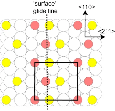
Fig. 1 shows a plan view of the Au(111) surface with added S head-group atoms to represent the adsorbed thiolate species, the (√3x√3)R30º and (2√3x3)rect. unit meshes being delineated by dashed and continuous lines, respectively. The S atoms are shown, arbitrarily, occupying fcc hollow sites, directly atop third layer Au atoms, and are shown in two different shadings. If the two shadings correspond to identical local geometries, the unit mesh is actually (√3x√3)R30º . However, if these differ in some way, then the surface mesh is (2√3x3)rect. For example, the two different molecules, represented by the differently-shaded S headgroup atoms, could differ in the orientation of the attached alkyl chain, although ultimately we will focus on the alternative possibility that they actually differ in the local registry site to the underlying substrate, implying relative lateral displacements of the two differently-shaded S atoms, or some kind of local Au substrate reconstruction. Fenter et al. [5, 6] pointed out that the key requirement to describe the observed diffraction pattern is that, in the schematic model shown in fig. 1, the relative positions of molecule 1* to molecule 1, and of molecule 2* to molecule 2, is given (in fractional unit mesh coordinates) by (0.25, 0.50). Then, if we define the location of the molecule represented by S atom 1, with a scattering factor f1, as (0,0), we may put molecule 2 at some arbitrary position (x2,y2) with a scattering factor f2 (allowing for a different possible molecular orientations of the species 1 and 2).
Then, summing over the four molecules at 1, 1*, 2 and 2*:
1 2 2 2
[ exp 2 ( )][1 exp(2 ( / 4 / 2))] hk
F = f + f πi hx +ky + πi h +k (2)
rotational domain of the (2√3x3)rect. structure. In reality, of course, the fact that the surface mesh is rectangular while the substrate has three-fold rotational symmetry, leads to the real surface layer comprising three symmetrically-equivalent rotational domains, leading to the diffraction patterns shown in Fig. 2 (c) and (d) for the situations in which the forbidden beams are, and are not, present. Notice, incidentally, that Fenter et al.
actually stated that 'the pattern of absences is characteristic of a centred rectangular cell' [6]. This is not correct. If the true unit mesh were to be centred, the diffraction pattern would be determined by the smaller primitive mesh, and many more diffracted beams would be 'missing'. Nevertheless, it is clear that the correct structure factor arguments described above were the basis of the conclusions of these authors.
Clearly the requirement that thiolates 1 and 1*, and thiolates 2 and 2*, have the relative coordinates of (0.25, 0.50) within the unit mesh, thus producing a pair of zig-zag chains of adsorbed molecules, significantly constrains the possible structural solutions. This is important to remember in the context of more recent STM investigations of the (2√3x3)rect. phase which show significant variations in the images, leading to suggestions for dodecylthiolate (n=12), for example, that this unit mesh may be associated with as many as five distinctly different structures [8]. The constraints placed by the SXRD result render this unlikely; specifically, there cannot be more than two distinct thiolate species per surface unit mesh that may differ either in local adsorption site, or orientation, or both. Indeed there is evidence that artefacts of the STM technique associated with tip and imaging conditions are the cause of these differences [9], and that the images all correspond to only one (2√3x3)rect. structure.
2.2 Low-energy electron diffraction, dynamical structure factors, and experimental results
written, however, if the fj are redefined to include not only single scattering from the jth
atom, but also all multiple scattering events involving this atom (see, e.g. [10]). However, an important implication of this is that the fj are also identical for adsorbate atoms (or
molecules) if the structural surroundings of these species are identical, a requirement which implies that these species actually define the unit mesh. The implication, therefore, is that the no systematic absences can occur in a LEED pattern correctly described by an inversion of the true primitive unit mesh. In fact there is one important exception to this statement, namely that if the structure contains glide symmetry, alternate diffracted beams are missing if the incident and diffracted beams lie in a common plane containing the glide line. This is a general result that does not rely on kinematical scattering [11] (although these missing absences are, coincidentally, also predicted by using a kinematical structure factor).
whether the ordering is improved at low temperature. It is, of course, well established that the (√3x√3)R30º and (2√3x3)rect. phases coexist for all the alkylthiolates (apart from methylthiolate), and that thermal treatments can influence the relative occupation of the two phases.
Inspection of the LEED pattern of Fig. 3(a) shows clearly that most of the diffracted beams that are absent in SXRD are present in LEED, as may be expected on the basis of the discussion above. Specifically, in LEED the only possible missing beams must lie in a line passing through the specular (0,0) beam and parallel to a glide line of the structure for each of the three rotational domains. Note, for example, that the (2,0) beam (circled in Fig. 3), that is absent in SXRD, is present in LEED. On the other hand, the (0,1) beam (surrounded by a square in Fig. 3) is absent in both SXRD and LEED. Fig 3(b) and (c) show the single and multiple domain simulations of the observed LEED pattern, and the single-domain simulation shows clearly that alternate diffracted beams in the <110> real-space direction (e.g. (0,1), (0,3)), and only these beams, are missing, behaviour characteristic of glide-line symmetry. Notice that these beams were absent not only at the specific energy (60 eV) at which the LEED pattern of Fig. 3(a) was recorded, but also at an arbitrary series of other energies (30 eV, 40 eV, 50 eV) at which photographs were taken. Further confirmation that these systematic absences are a result of glide symmetry was obtained by rotating the crystal away from the nominal normal incidence condition used to record the LEED pattern of Fig. 3(a). For off-normal incidence, glide symmetry only leads to systemic absences if the plane of incidence contains both the glide line and the 'missing' diffracted beams; in other geometries (involving sample rotation about an axis that is not perpendicular to the glide line) these beams gain finite intensity although, of course, for small deviations from this geometry the intensity may still be weak. Nevertheless, at least some of the beams missing at normal incidence were found to become visible at off-normal incidence conditions.
technique, namely low energy (He) atom diffraction (LEAD) [12]. Although there seems to be some ambiguities in the report of this work, it seems clear that at least some of the 'missing' diffracted beams of the SXRD experiments were detected in the LEAD experiments. The conditions of these LEAD experiments were such that a significant degree of multiple scattering by the surface corrugation potential is expected, in which case the conditions governing missing beams should be similar to those for LEED, rather than for SXRD. This LEAD result is thus consistent with our findings with LEED. Indeed, in a LEAD study of methylthiolate on Au(111) it was reported explicitly that a (2√3x3)rect. phase was formed which did not show the systematic absences reported for SXRD [13]; this is, however, the only report of this structural phase being formed by methylthiolate, and it is possible that the true periodicity was that of the (3x4) phase reported more recently for methylthiolate under certain conditions [14], and also seen in some of our studies.
3. Structural implications:
3.1 Possible models for different S-headgroup sites.
may lower the symmetry. They cannot, however, raise the symmetry, so having the S headgroup atoms consistent with the symmetry requirements is a necessary, but not a sufficient, condition for an acceptable structure. There are also clearly steric considerations governing the possible orientations of the alkyl chains of different adsorbed molecules that define structures that are physically possible. These effects do not, however, lead to rejection of any of the models that we find to be consistent with the symmetry constraints applied only to the S head-group atoms.
The simplest model satisfying the diffraction symmetry constraints is illustrated in Fig. 4; this structure is quite similar to that of Fig. 1, but the two different types of thiolate are now explicitly in different local registry sites, namely the fcc and hcp hollow sites, directly above third and second layer Au atoms, respectively. We should, perhaps, remark that there is ample experimental evidence that the S headgroup atoms do not occupy these hollow sites(e.g. [15, 16]), but we will first consider only the symmetry constraints of the SXRD and LEED results. The different shading has been retained to show that this structure retains the two zig-zag chains required for the SXRD beam extinctions; the different shading could represent the fact that the alkyl chains attached to these S head-group atoms have different orientations, but here we consider only the S atoms. This structure retains the relative positioning required for the SXRD systematic absences. Superimposed on this diagram is a dashed line labelled 'surface' glide line. This line marks the position of a glide symmetry line with respect to the S overlayer atoms, and to the outermost Au atomic layer, but not with respect to the lower Au layers, as the glide operation transposes a fcc hollow to an hcp hollow and vice versa. Consideration of the scattering components contributing to the effective (multiple-scattering) LEED atomic scattering factors for the S atoms, however, shows that this structure should lead to the missing diffracted beams in LEED characteristic of a true glide line. In particular, the effective fj for the S atoms contains three components, single scattering, multiple
However, the third component contains inequivalences for the S atoms of the same shading; for example, the fcc S atoms at the corners of the unit cells marked in Fig. 4 have other fcc atoms to their right (at a relative position (0.25, 0.50), whereas the fcc atoms that lie within this unit mesh have other fcc S atoms to their left (at a relative position (-0.25, 0.50). This left-right asymmetry is irrelevant in the structure factor argument used to define the systematic absences in SXRD, but in LEED it will, in general, lead to finite amplitude in the diffracted beams that are forbidden in SXRD; however, the fact that this term has glide symmetry is sufficient to retain the subset of extinctions expected for a true glide symmetry of the complete structure. Another way of viewing this argument is to recognise that the left-right asymmetry is only important for diffracted beams that lie to the right or left of the <110> azimuth, so only beams with a finite value of h will not be extinguished.
surface moiety, in which an Au adatom occupies a bridging site on the Au(111) surface, and two thiolate species are bonded to this with the S headgroup atoms on opposite sides of the Au adatom such that they occupy near-atop sites relative to the underlying surface Au atoms. This moiety has been identified for both methylthiolate [18] and propylthiolate [19], the alkyl chain of the propylthiolate apparently being near-parallel to the surface at this low coverage. In addition, however, a recent combined molecular dynamics, SXRD and photoelectron diffraction investigation of the (√3x√3)R30º structure formed by methylthiolate on Au(111), has invoked this same moiety as a key ingredient of the structure [20]. Fig. 5(b) shows the only model that we have been able to identify, based only on ordering of these Au-adatom-dithiolate moieties, that satisfies the SXRD and LEED symmetry requirements. Specifically, the structure has the zig-zag placement of atoms required to obtain the SXRD beam extinctions, but also contains glide symmetry of the surface component (adsorbate species plus outermost substrate layer), while each Au-adatom-dithiolate moiety is identically positioned relative to the underlying substrate, so it would give rise to the observed LEED beam extinctions. It is interesting to note that this model of Fig. 5(b) is essentially the same as a new structure proposed on the basis of total energy calculations by Grönbeck et al. [21].
In searching for structural models that satisfy the constraints of surface periodicity, thiolate coverage, and symmetry implied by the SXRD and LEED, we have only considered models involving adsorption at high-symmetry sites. Clearly, lower-symmetry structures may be envisaged, but these can be regarded as involving atomic displacements from the high-symmetry sites, with all such displacements retaining the required symmetry. For example, the structures of figs. 4 and 5(a) still satisfy the symmetry requirements if the thiolate or adatom-plus-thiolate species in the fcc and hcp hollows move apart (or together) along the line joining them. Similar distortions of high-symmetry structures that fail to satisfy the high-symmetry requirement, however, do not gain new symmetry.
Recently, a study of the Au(111)(2√3x3)rect.-hexylthiolate surface phase by Cossaro et al. [22] has led to a particular and rather complex structural model; we now consider the extent to which this model satisfies the symmetry requirements discussed here. Using a combination of molecular dynamics calculations and SXRD experiments (similar to the earlier study of Mazzarello et al. of the (√3x√3)-methylthiolate phase [20]) they proposed the structure shown schematically in fig. 5(c), albeit with some partial disorder and some local lateral distortions. This structure contains three key ingredients, namely: (i) Au surface vacancies; (ii) thiolate species adsorbed in bridging sites; (iii) Au adatoms in bridging sites with associated thiolate bonded to adjacent atop sites, creating a structure that is locally similar to the Au-adatom-dithiolate species discussed above, but with the thiolate species 'shared' between Au adatoms. This third component leads to the formation of -adatom-thiolate-adatom-thiolate- chains somewhat similar to the adatom/thiolate polymeric structure proposed in earlier theoretical calculations by Grönbeck and Häkkinen [23]. We note, though, that in the optimised structure of Cossaro
et al. the average occupation of the Au adatom sites is only 60%, so locally these chains may not be continuous; in SXRD these fractionally-occupied Au adatom sites are represented by atoms with 60% of the scattering strength of true Au atoms. A similar disorder is reflected by one of the two nominal vacancy sites that also has 60% occupancy of Au atoms.
Inspection of the model of Fig. 5(c) shows that many features of this model satisfy the constraints imposed by the SXRD beam extinctions. In particular, the relative positions of the thiolate species in the adatom-thiolate chains, and of the bridge-bonded thiolate species, all occupy zig-zag rows with relative coordinates of (0.25, 0.50) as required. This would also be true for the Au surface vacancies if the two vacancies per unit mesh were identical, but the fact that one of them has 60% Au atom occupation breaks the required symmetry. More seriously, the Au adatoms do not satisfy this requirement; scattering from these atoms should lead to finite intensity in the 'missing' SXRD beams. The fact that the row of Au adatoms have relative fractional coordinates of (x1,y1) and (x1,y1+0.5),
such as (0,1) and (0,3) will still be 'missing' from the diffraction pattern. This is not true for beams such as (2,0) and (2,2) however, and a calculation of the diffracted beam intensities of these beams using the ROD program [24] and the exact structure proposed by Cossaro et al. [22] indicates that these diffracted beams should have comparable intensities to some reported by these authors. Moreover, it is clear that this structure does not satisfy either the total or partial glide symmetry requirements of LEED, and should therefore not show the observed LEED extinctions.
These symmetry arguments formally lead us to reject the model of Fig. 5(c), yet this model was supported by SXRD data. The authors reporting these data do remark on this apparent inconsistency. Specifically, they state that the predicted intensity of the apparently 'missing' beams was actually a factor of five lower than the weakest observed beams in their experiment although, as remarked above, our calculations based on their structure suggest that this should not have been the case for all of the 'missing' beams, but only for a subset of them. It is possible that the key beams that should not be extinguished were not included in the measured data set. Moreover, it would be surprising if the far more significant deviation of this structure from glide symmetry would not lead to significant, readily measurable, intensity of the 'missing' beams in LEED.
4. General discussion and conclusions
exist, but we have been unable to identify one. Notice that apart from the structures discussed here, any model based on co-occupation of local sites of different local coordination, such as hollow and bridge, or bridge and atop, cannot satisfy the requirements for glide symmetry in the overlayer.
Of course, symmetry arguments are exact, and experimental data and the true structural order of surfaces are never so perfect. The effects of translational and glide symmetry on perfectly-ordered structures predict that certain diffracted beams have identically zero intensity in different techniques. In an experiment, however, it is never possible to distinguish, with complete certainty, between zero intensity and a very low intensity (in the presence of some finite background intensity due to static and dynamic disorder). This remark is particularly germane to the structures involving Au adatoms. The scattering cross-section of these atoms of high atomic number, Z, is much greater than that of the S, C and H atoms of the thiolates for both X-rays (scaling as Z2) and electrons , so if Au adatom structures are involved, the influence of the alkyl chains, in particular, may be too weak to influence significantly the measured diffracted beam intensities.
Beyond these pure symmetry arguments, consideration of other experimental evidence indicates that of the three models discussed, that involving thiolate species adsorbed on an unreconstructed surface in the two hollow sites (Fig. 4) can be clearly rejected. Specifically, there is now ample evidence from photoelectron diffraction and NIXSW that the S head group atoms occupy local atop sites on Au(111) in a range of thiolate structures, notably for the (√3x√3)R30° phases of methylthiolate [15, 16] and butylthiolate [25], and for the striped phase of butylthiolate [25], hexylthiolate [26] and octylthiolate [25]; none of these cases show occupation of the hollow sites of the model of fig. 4. A contrary conclusion, from an SXRD study of the (2√3x3)rect. phase of hexadecylthiolate [7], was that mixed fcc/hcp site model of Fig. 4 gave the best fit to the experimental data, but this work predates the evidence for Au adatoms, and structural models involving adatom-thiolate moieties were not tested.
NIXSW, no structural model of the (2√3x3)rect. phases based on atop adsorption on an unreconstructed surface is consistent with the symmetry requirements of the diffraction results. However, both Au-adatom-thiolate moiety models place the S atom in local atop site; as such, both of these models (Fig. 5(a) and Fig. 5(b)) are consistent with the experimental results. NIXSW cannot distinguish adsorption atop a surface layer atom and an adatom in a bulk continuation site, while photoelectron diffraction, particularly normal emission energy-scan data, shows only very weak sensitivity to this distinction. These two structures are thus the favoured candidates to describe the true structure. Only one piece of experimental evidence appears to distinguish them. Specifically, NIXSW data of mixed (√3x√3)R30° and (2√3x3)rect. phases of hexylthiolate and octylthiolate [17] provide evidence for the S headgroup atoms to be atop Au adatoms in both the hollow sites. This evidence for partial occupation of S atoms atop Au surface atoms in hcp sites relative to the underlying substrate is not consistent with the Au-adatom-dithiolate model.
In conclusion, we have shown that possible solutions of the structure of the Au(111)(2√3x3)rect.-alkylthiolate phases are very heavily constrained by the pattern of systematic absences of diffracted beams seen in SXRD (as identified by Fenter et al.) and LEED (as presented here). Three possible structural models are identified which match these constraints. One of these models, involving adsorption in fcc and hcp hollow sites on an unreconstructed surface is clearly inconsistent with all of the published NIXSW and photoelectron diffraction data. Of the other two models, both involving Au adatom-thiolate species, only that composed of adatom-thiolate species atop Au adatoms in (or close to) fcc and hcp hollow sites aligned in the <211> azimuth appears to be compatible with both the symmetry requirements and all other published experimental data. Re-evaluation of existing (published) SXRD data in terms of this model would be of very considerable interest.
Acknowledgements
Figure Captions
References
1 L. H. Dubois and R. G. Nuzzo, Annu. Rev. Phys. Chem. 43, 437 (1992). 2 A. Ulman, Chem. Rev. 96, 1533 (1996).
3 F. Schreiber, Prog .Surf. Sci. 65, 151 (2000).
4 C. Vericat, M. E. Vela, and R. C. Salvarezza, Phys. Chem. Chem. Phys. 7, 3258 (2005).
5 P. Fenter, P. Eisenberger, and K.S. Liang, Phys. Rev. Lett. 70, 2447 (1993). 6 P. Fenter, A. Eberhardt, and P. Eisenberger, Science 266, 1216 (1994).
7 X. Torrelles, E. Barrena, C. Munuera, J. Rius, S. Ferrer, and C. Ocal, Langmuir 20, 9396 (2004).
8 B. Lüssem, L. Müller-Meskamp, S, Karthäuser, and R. Waser, Langmuir 21, 5256 (2005).
9 A. Riposan and G.-Y. Liu, J. Phys. Chem. B 110, 23926 (2006).
10 D. P. Woodruff and T. A. Delchar, Modern Techniques of Surface Science – Second Edition (Cambridge University Press, Cambridge, 1994) p38.
11 B. W.Holland and D. P.Woodruff, Surf.Sci. 36, 488 (1973).
12 N. Camillone III, C. E. D. Chidsey, G. -Y. Liu, G. Scoles, J. Chem. Phys. 98, 3503 (1993).
13 M. F. Danisman, L. Casalis, G. Bracco, and G. Scoles, J. Phys. Chem. 106, 11771 (2002).
14 V. De Renzi, R. Di Felice, D. Marchetto, R. Biagi, U. del Pennino, and A. Selloni, J. Phys. Chem. B108, 16 (2004).
15 H. Kondoh, M. Iwasaki, T. Shimada, K. Amemiya, T. Yokohama, T. Ohta, M. Shimomura, and K. Kono, Phys. Rev. Lett. 90, 066102 (2003).
16 M.G. Roper, M.P. Skegg, C.J. Fisher, J.J. Lee, D.P. Woodruff, and R.G. Jones, Chem. Phys. Lett. 389, 87 (2004).
17 M. Yu, N. Bovet, C.J. Satterley, S. Bengió, K.R. J. Lovelock, P. K. Milligan, R.G. Jones, D. P. Woodruff,and V. Dhanak, Phys. Rev. Lett. 97, 166102 (2006). 18 P. Maksymovych, D. S. Sorescu, and J. T. Yates, Jr. Phys. Rev. Lett. 97, 146103
19 P. Maksymovych and J. T. Yates, Jr., private communication; P. Maksymovych, D. S.
Sorescu, and J. T. Yates, Jr., to be published.
20 R. Mazzarello, A. Cossaro, A. Verdini, R. Rousseau, L. Casalis, M.F. Danisman, L. Floreano, S. Scandolo, A. Morgante, and G. Scoles, Phys. Rev. Lett. 98, 016102 (2007).
21 H. Grönbeck, H. Häkkinen, R.L. Whetten, J. Phys. Chem. C 112, 15940 (2008).
22 A. Cossaro, R. Mazzarello, R. Rousseau, L. Casalis, A. Verdini, A. Kohlmeyer, L. Floreano, S. Scandolo, A. Morgante, M.L. Klein, and G. Scoles, Science 321, 943 (2008).
23 H. Grönbeck and H. Häkkinen, J. Phys. Chem. B 111, 3325 (2007). 24 E. Vlieg, J. Appl. Chryst. 33, 401 (2000) .
25 A. Chaudhuri, D. Jackson. T.J. Lerotholi, D.P. Woodruff, V. Dhanak, to be published. 26 T. Shimada, H. Kondoh, I. Nakai, M. Nagasaka, R. Yokota, K. Amemiya, and T.