APERTURE.ANTENNAS
A thesis presented for the degree of
Doctor of Philosophy in Electrical Engineering in the University of Canterbury,
Christchurch, New Zealand
by
A.R. Jamieson, B.E. (Hons.)
Abstract
Comput,ational and e~perimental methods f0:t: evaluating the radiat:i,on and coupling' charact~rist,ics of 'wide-beam antent),as a+"9 presented. Tne application of these met}:lods, to a practicalantElJ).na is illustrated by a combined
theoretical an4 experimental :i,nvestigati?nof a circular. waveguide aperture antenna flush mounted in a larg~· metallic .ground plan,e.· ,
Tl:te design .. and d~,velopment,of, the c().axialantenna,' a wide-beamradiato:p sui tabl~ .. for incorpol:'atiop into a wide.
scannin~ arr~y an~ertna, is ,also ,presepted. Th~santenna is theapertu~e equiva+ent of three mutually perpendicular dipoles,,' and has ,the c~pabi,lity of tr.ansmi tting or
I am· especially appre,ciati veof tp.e guidance and he lp prof::fereo. by my supervisol:! Mr;R~H .,~, Bates. His assistance over the· duratic;m· of ,the project ha~ been invaluable,.
To . the. workshop staff, of. the Electrical Enginee,ring Department ,~I wish. to e:x;press .my,gratitude for
.tpe
wqrkmqn':"" li)<.e mq,nner in, whichtfleYGonstruct~d theco9.xial and .. circular ,waveguide. an i:ennas.Abstrac.t .
Acknowledgemen ts
CONTENTS
PART 1: Formulation of analytical techniques CHAPTER 1: Introduction
CHAPTER 2~ The Near-Field Technique 201 IntroduQtion
202 Formulation of·the N~Fo~o
2021 Field representatiQ~s
2 022Separability:of the field values ~ 2 023 Field measurements
203 Sotirce field distri~utions 204 Brror analysis·
2041.Truncatign error 2042 Field· sampling error 2.5 Critique of ,the NoFoT~
CHAPTER.3 ~ Scatte:r;-ingmatrix. approach to ,the study ;of. mutual coupling
3.~ Introduction
3.2 Netwol;"k'description of antenn,as
3 .3 Calibration of the scatter-ing properties
1-1
1-8 1-8 1-16 1-16 1-23. 1-26 1-28 1-30 1-;-30 1-31 1..;.,38
1-42 1-42 1-54
3.4 Mea~urement procedure for mutual coupling estimation
3.41 Direct path coupling 3.42 Field representation
3.43 Mutual impedance ot' arbitrary antennas
3.5 Conc;Lusion
:HAPTER 4: The experimental and computational deter-mination of the performance of a circular waveguide antenna.
4.1 Introduction
4.2 Near field formulation
4.21 Waveguide mode aperture field representation
4.22. Vector mode field representation 4.23 Aperture field distribu~ion 4.3 ·Aperture admitt.ance
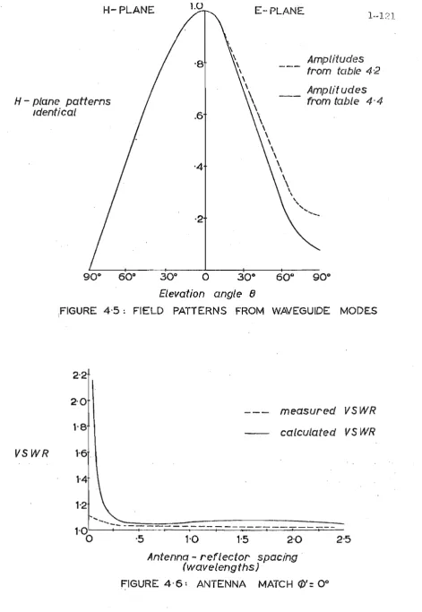
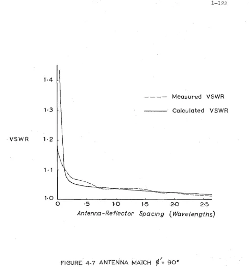
4.4 Mutual coupling study 4.5 Reaults and discussion
4.51 Far-field radiation pattern 4.52 Aperture field
4.53 Determination of mutual coupling 4.54 Suggested·. topics for further atudy
PART 2: The coaxial antenna CHAPTERS: The coaxial.antenna
5.1 Introduction
5,2 Literature review for the coaxial antenna 5.3 Coaxial wavegl..1,idemodes of propagation
5.3.1 ·TEM mode.
5.32 TE and TM modes
5.4. Coaxial antenna - .. three dipole compari9>on
CHAPTER 6 : .Antenna field .patterns 6.1. Introduction
6.2 Far-field"modal radiation pat~erns 6.21 ·Far-field vector potent~al
radiation. formula.
6.22 Mo.dal radiation patterns 6.3 Coaxial al)teffi1.a radiation patterns
6.31 Aperture highe;t:' -o.rder. modes 6.32 Estimation of total Tadiation
pattern
6. 33·Effect!;l of aperture "higher order modes
6.4 Ground plane effects 6.5 Conclusion
i i i Page 2-1 2-1 2-7 2-12 2-14 2-1·4 2-16
CHAPTER 7: System design 7.L Introduction
7 .,2 Polari~ation structure
70,21 Polarization vectors'
7.22PolarizatiQn group structure 7.3 System'circuitry design
7,; 31 Simple four-port system, 7.32 Modified system
7.4 Sysirem performal1ce
7.41 Maximum· power condition' 7.42 Polarization state cQntrol" 7.~ Discussion
CHAPTER 8: Element design 8.1 Introduction
8.2 The"waveguide design 8.21 The main seGtion 8.22 The b;ming section 8.23 The,transition seQtion 8.3 Probe design
8.31 Method of mode excitati9n 8.;32 Mag:netic loop probe, impedance 8 .. 33 Grounded and capaci tive,loaded '
loop probes
8.4 Coupling network
8~41 Loop probecross-:-coupling effects 8.42 Coupling elimination
8.5 Matching network'
8.51 ,Th~ line transformer
8.52 The parallel stub mCltching network 8.53 Strip~line network,
8.6 Discussion
CHAPTER 9: Discussion ofth~ coaxial antenna, 9.1 Introduction
v Page 2-88 2-88 2-89 _ 2-92 2-92 2-:94 2-96 2-97 2-112 2-112 9.2 Further applications of the coaxial antenna 2-114
9.21 ,V.H,.F. ,mobile, station antenna 9.22 Polarization calibration anteri~a 9.,3 Antenna design modificat~ons,
9.4 Suggested ,fl,lrther,experimental studie9 9.!;i Conclusion,
APPENDIX I Spherical v~ctor mode,s'
2-114 2-116 2-117 2-120 2-:-123 A-I APPENDIX II The electric -:vector potential A..,. 4 APPENDI,X lIT:' Addition theorems for spherical vector
modes A..,. 6
APPENDIX IV Proof of stationary nature of ,aperture;
adrnittanqe expression A-8
APPENDIX V, ., Reduction of the variational expressiop
for aperture ,admittance A-II
This thesis discusses computational and experimental methods for evaluating the performances of antennas
characterised by vlide beam "radiation patterns 0 The design
and development of a specific wide beam antenna suitable for inclusion in a radar or communication array antenna is also presentedw
In applications employing a wide beam antenna as an isolated radiator, the impedcince match and the far-field radiation pattern are thep:Eoperties of most interesto The impedance can always be determined simplyo Although the far-field radiation pattern may be determined experiment-ally by performing measuremHnts in the far-fieldQ under
certain conditions i t is preferable to infer the ,far-field pattern from near..,fieldmeasurementso A computational procedure is developed which permits the complete three-dimensional far-field radiation pattern of a wide beam
antenna to be inferred from limited near~field measurements o
This technique is essentially an extension of methods
The behaviour of an antenna in an array environment differs from its behaviour as an i$olated radiator 0. because
of the effects of mutual coupling ... between the elements of the arraYe In view of the. current interest in array
antennas 4-6 the
dev~lopmentof'
new. methods' for estimatingmutual coupling effects is of practical intereste A technique is presented for computing coupling effects from experimentally derived scattering and radi~tion characteristics of individ-ual array elementse This element-:by~element approach is uE/eful, since i t enables acomplete_,ar.ray· to be designed from measurements performed on a s.ingle array elementc· A simplified, approximate approach "is also developed and this is applied to the cylindrical aperture antennaj and the estimate of the coupling effects is ... compared with the corresponding measured effects.
The development of the coaxial_antenna for use in a wide scanning array is also discuss.edo A feature of .this
antenna, which is the aperture equi.v.alentof three mutually perpendicuHl.r dipoles f is its capahili ty of transmitting
or receiving signals of arbitrary p.olarizationo·
The thesis is divided into two pa.rtspthe formulation of analytical techniques to evaluate the performances
of an antenna, and the design. of. the coaxial antennae . Thus, Part 1 is a contribution to the general, theory and, .in
3
New material is included in Chapters 2=4 and 6~9 i7
with Cha.pters 1 and 5 being introductory 0
Part 1 includes Chapters 1-4 i7 and contains the
descript-ion of the analytical techniqueso A method for inferring the complete far~field radiation pattern of a wide beam antenna from limited nea~~field measurements called the near .... field technique isin"troduced in Chapt.er 2 c Two
formulations are presente-d~ . one expressed in terms of waV'e= guide modes of propagation" and the other based upon a
spherical vector mode field representation" The waveguide mode formulation is shown .to be sui table for inferring
the field patterns ofapertlireantennas mounted in ground planes Q while the spherical mode formulation is applicable to any three-dimensional antennap but is best suited to wide beam antennas u An "estimate of the aperture field
distribution afan apertur:eantenna is shown.to be possible by applying an extension of .this technique." The near-field
teChnique is an improvement to e.xist,ing methods for
inferring antennapatte.rns v' .and is new in its applica,tion
to wide beam' antenna.s mounted above ground planes., F'urther~ more 0 the p):'esented .techniq:ue is complementary to the
:3
methods formulated by _ Jensen for narr()w beam antennas and in conjunction with tl1.ese met,hods completes the three=
A scattering matrix approach to the problem f determining mutu.al coupling effects in finIte arrays is discussed
in Chapter 30 The estimation of the total coupling effects requires a knowledge of th6full scat.tering
properties of the array elements 0 and the. :range ofmeasure~
ments necessary. to determine the scattering-properties of a representative element is derivedo Anapproximat~e coupling description based upon direct pa:th coupling effects is also formulated 0 This approximate approach :represents
a new technique for the design of array ante;nnas 0 In
Chapter 4g the performance of a circular cyl~ndrical waveguide
antenna is evaluated by applying the t.echn.iques presented
in the previous chapters a A new formulation of the variational
expression for the aperture admittance of this antenna is
also includedo Chapter. 4 conclud~s with suggestions for further
study. Part. 2 contains Chapters 5-90 . and outlines the design
of the coaxial antenna 0 • This new p wide beamo .aperture antenna supports three orthogonal modes of propag.ationp
whereas previously designed coaxial aperturean:tennas generally suppo.r:t only. pne mo.de 0 Thus/? the pres6l:),te.d design is
entirely new c . Chapter 5 introduces the:. ccaxla.l a.nte.nna and
specifies· the constraints on .the element and sys.tem designs· of the antennae A review of the relevant Lit.erature is also includedo In Chapter 6 the radiation patt;£;l~ns of the
aperture, Since these modal patterns are.only first order approximations to the actual patte.rnsof the ante,nnan. the application of the near-fiel.d .. technique
to the ,coaxial antenna is also fqrmulatedQ , • The system
design is pre'sen ted i.n Chapter' Thiso.eSCTibes the polarization structure ; and the rcui.try required
1··=·5
to provide control over the mode ofopexation of the antennae Two system designs a.re givenow:i.th each
considered as the. optimum system for differ:entapplicationsQ The element design ba§ed on· ah experimental study.
performed at L~bancj is' discussed in Chapter 8..; Thede$:igns. of the waveguide sections of the antenna.v.' the.axei tation probes 9 . and the necessary matching netw:orks.are included"
The mutual coupling, effects between. probes are>studied with. particular emphasis placed·onthe compensation
oftPesedetrimental effects o · Although designed expli,ci tly
for an array applica tlon g, the, radi at.ion .pr.:opertil';ls of ~ the,
coaxial antenna rena.er'it useful a$, an isol.a-ted,radiatorg .,
and two such',uses· are sugges'l::;;ed'in Cnapt:er9o Modifications to tb,e antenna parameters which. will . imprr~we' the perfoJ['m~'
anceof the. antenna are also discussedo ,F.inally g
The n~meri,Ga1.compp.~atipns ,recorded in Chapter 4
w~reperformed on the IBM 360/44 computer of the University~. of Canterbury .Computer. Centr-e, while· the' designs of the
matching nE?tworks o\:tt1in,ed in.Chapters 8 wer:~ evaluat.ed on theBAI 640 compute.r of the. Electrical Engineering Depa+tmentoWi th ·the ex<;~pti,on of.the st.andar,d .. IBM sub,.,.. routines BESJ .for cyJ,..indrioal,.Bessel funcbiQ,n.s· .and MINV for mat:r:ix. in,vereion I ' all .. cpmputer.prog~art1.s .. used ',were
written by
the.
autho17 in.FQRTRAN IV.Publications; . to date'. on top:i.cs' re.1evant. to the, thesis are,:
(i) RdH .T. Bates~and 'A!:R. Jamieson:'· II Tow.ards . ..:measuring·
Faraday Rotatio.hby rada+, with min~mUmerrorl1 , . paper'pres~ntec;1 at~ZAAS Conference,~,Chris,tchuroh I
N.Z~, January
19GR.
(ii) R.'H.T. Bates .. and A.R., Jamieson:, uTowards .reou,9ing'" errors' inra'da:r: ineas\lrements of Faraday RtlJ'tationll
, '
Electrol1ics' Ll9tters',
!,
nH" ~9 th, '-April 1~68,pp 155..,156,9
(iii) A.R~, Jamieson and R.,H.IJ;~, BateS: nAn ae:r:;ia1,capab,le,o:f; radiating any, po:J.a.rizati'On," , paper presented at NelconII confe,rence, Auck1and"r.Zo, August:. 19,680 (iv) A.R •. Jamieson and R.H.T., Bate.s: liOn the accurate
1-7
Additional'p~pers in preparation inc::lude~
(v) Ao R" .Jamieson and ,Ro Ho To . I?ates·g uTriple po1ari~ed·
coaxial aE?riaJ.,; HI ~,to be submitted t.o. I:ERE JournaJc 0 (vi) AeRD Jamieson anq RDHbTD BateS~. l!Ante,nn~ ... :r:ad:L,ati,on ,
pattern inferred from· near:~fieldmeasurements,e@ to be submitted~to ProeD lEEo
(vii) A~ Rb Jamieson and R.;..Ho'To Bates; ~Gneterm:Lni.ng array perfo.rmance .from· mea$urem~ntspe:r:':fo:r:med
In .common w:Lth' classioal nOrnencl,atu:t:e in optics the-elect.romagneti,c fiElldradiated by an ante.nna has been traq.ionally di vicied in to th.e induction fieldl'. the Fresnel
region oa,ndth.~ Fraunh.ofer· Dr far"':'field region 0 • Th~ indue on fiElld an,dthe Fresnel region are freq1,lently consideredr.,
collecti vely r ,as the near-field r~giono Al tho:ugh the, trans~· ition fromtlle nearc..field toth~ far~fie~d is gradual with. no abruptchangesf the accepted oIl=p.xis minimum: range for
the. far...,fiEHd region. may. be defined as the range allpwing amax,imum phase differenoeof1T/8·radipns between the :radiation fields.emi tting from various pa;rts. of the
t . '1 '.
an enna 0 For an antenna wh9se apertur~ has a maximum
dimension D,u~ and i s operat~ng at a' wavelength. Ii ,~, this far",:, field raJ;lge is 2D2/\0 Radiati0n pat.tei:ns.me~sured within this range are. classi·fied asne.ar-f::i.eldpa.tt~rns" while:; those measured, at'.grea:ter, rap-ges are.,far~;Eield patternso
The evaluation of',the performan,ce
an
antenna in a system enviropment often requires a,de,t.ol,iled knowledge of tn.eradiat:i,.Oti pattern· of .,t.he ant,enn{iQ In the study a,rray antennas il,forexample", b6tl:l; themutllal. coupling. between, elerp.ents' in the ,'array. and ,the ra.diati.on9
pattern of the isolated individual elements;:, To be
ace.urate ~ radiation' pattern measurements must be performed within the
far~field
region 8 of theantenna.o Forelectr.ically . large antennas ~ such as used in comrnunicatJ.on and sat'ellite receiving stations ~ this range may' be of
the order of many miles [1 making accurate .far~:field measu:t'e=' merttsdiffibult. Various techniques have .been developed involving
extra~terr~stial ranges9~lO
and the use of air-craft and satellites as both signal sources and pasBive scatterers 8 but, their· usefUlness' remains limJ. ted by costand' accuracy considerations 0 " Elect:tiqally, sma}'l antennas
of the' type commonly used in wide apgle' array applications [1 are characterised by wiqe.beamradiation patternsa
Accurate pattern measurements performed sole'ly in the far-field of these antennas are often difficulto especially when the ant,enna is .mounted above a ground plane Ii . ,since the
radiation effectsresult~ng from the edge currents of the finite ground' plane Il and, the effects of spuri:o:uS reflections
from the surrQundings~.tnay constitute a significant portion of the. total radiatipnin the far=fieldQ ' In· thenear~field.
the actual radiat.ion from the. antenna preciominate-s ,.over these -secondary effects Q. Since ~.' by, pe.rformil,lg measurements
technique for inferring the far-field radiation pattern of wide beam antennas from near-field measurements,"
Althollgh a comprehensive review of existing methods for inferring antennapatterns'has·recently been published b Y Jensen , 3 ~t ~s . . never t h l ~ eSs approprlate to lnC u e a s o r t ' . I d h
litE;!rature review to complete the background of the technique which is presented in this thesis 0
The approach to this prdblemiptroduced by Bates and
Elliot 11: Wc;l5 ,based upon tl1,e dev'elopment of an ,asymptotic .. series representing the near-·f.ield pattern in terms of the far-fj.eld pattern and, correction terms a Since derivatives of the field pattern are. included wi,th'the. c0rre~ti.on termsg these methods are sensi ti,ve to e:trqrs il;l. the measured values of thenear~
field. patternoTh.uS,·experimental difficulties.emerge in measuring'Phe near;....fieldpattern to sufficient ,accuracy" To measure the fields at, a point in ispace 'an infini tesimaJ,.
Hert,zian dipole: (magnetic;orel$ctric} il:j usually assumed in theory II but·. in 'practiqep to provide adequate signal strength
for the detecto::l='~an antenna with a, finite ,si~ed aperture is req\lireda Using' the plane wave'spectrllm conpept12 ' Brown13 { investigated the effects ,of the aperture size of therneasuring antenna ongainandQ in particular, pattern
measurementsp and demonstrat~dtha:t:; the, procedure of Bates and Elliot yd.,elds accurate predictions " of the field patterns only when sma],l aperture ',recei ving a.ntennas are used to
1-11
for ape1:'"tu:r::e antennas described by
BickmQre14~
involvesthe readjustment of the aperture phase distribution to produce the far-field pattern as closely as possible in the near~field
regiono This method has been considered by several authors (f or a reVlew see . S " oeJlma 15) ~ ,an ,goo 'agrreemen d d t b e ween t the near-field patterns of focused antennas and the
15
corresponding far-field patterns has been reported 0 But
since the necessary phase' adjustment is pJ::'acticable on only certain classes of antenna,; notably reflector antennas ~ the technique is of-.limited u$efulnesso
In the method presented by Brown. and Jull1 ,
-the total radiation field from -the antenna is represented,by a complete set of· orthogonal' cylindrical wave functions v or
harm~:mics, and complex -. modal - amplitudes a By measuring the
near-field pattern around a cylindri~al surfage enclosing the an tenn-a; the' measured field is expresse1d as a.Fourier serie:;; in the wave functions 0 The unknown amplitudes are
then determined by Fourier analysis of the measured f:i,elda
Since a c0mpleteknowledge of the modal am.plitude:::; at a point in the-region exterior to'the surface which circum-scribes 'the antenna~serves to define the field? everywhere in that region f', theseampl.:i- tudes specify the' total far-field radiation. pattern. Although originally stl9'gested for
b,ro'-dimensional problems, the method can be extended v in principle~
inherent'disadva,ntageof requiring measurements of the near~ field patterno in both modulm~andpha\se 0 to be perfoxmed over, a spherica~ surfage enclosing the antenna'o Further-more~ " thE? amount of computational effort involved in the term-by-term' modal,', analysis requiring numerical integrat,~,on of such a three~dimEmsional field is consiq,erableq ThE:~
effects of the 'aperttpce siz,e of,·themeasuring antenna' we~e also considered -by Brown' and Julio By inverting
the first few. terms of the asymptotic expansion for: the f ' ld t t ' d b d' t ' ~,16 near-' 1 . e ' pa ' ern measure· y a ·;:t,ree :J.,ve anl"enna· 0
Julll
?
developed anequivalent~
but approxima:teo asymptotip series e:xpressing the'far-field pattern of a'two;'dimensionq.l trans.mi t,ting antenna inter:ms' of the measured near-field pattern and its deriva1;:iveso The· derivatives are calculat'ed from the measured near~field ,pattern?, This must; bemeasured acc1,lrately 0 ,sinc~ the, calc'\.l,lab~d val,ues of the, deriyatives are sensitiveto.even,smal;r errors in the, measured datao' Using this technique.", t.hemain . . ~ , b~am and major si4e lobeS' of the radiation patternot a'na~r.ow beam antetlna have' been inferredgto a
.
r~a~6nahleacc:uracYI'.'f,rom . ,near-field measurements performedsolEtly wi thll!- the, 11 .
principaJ,. ang1J1ar., rang~ of the' patt.er~ -r)' In comp?rison j the more exaqt -Fourier series method of' Brown and Jull requires measurement oithe fieldal;L armmd, theant,ehnaQ
wave functions arenecess.ary to represent the .field accurately 0
which generally increases the computational effort involved in determining the modalcamplitudes 6
Others to. apply the.FQurier seri~s method include
Blakey2p 18 and Martin 19 0" Blakey developeq an on:""".line . system for processing the neax-:field measurements .. of .atwo=dimensibnal antennapwhile Martin applied high speed digital.computer
techniques to infer the far,,-:,field pattern of .aline. source antennao ' The sensitivity' of themet:hod. to.:r::andom e.rrors··
in the near .... field meal;>urements.was also investigated by
Ma+tin~90
The three"-dirilensional extension.ofBrown and JulIus20
method was used by James and Longdon toinfe±' the far-field pattern' frqm me<;tsurements 'of .the radial component of ,the
near-t'ieldo . They a'lso applied- a matri.x; method to solve for the unknown, modal ampli tuGl,es whel'l. thenear"'.field '·pattern· is known' onJ,y at discrete pomtsJ6L Jensen
3 ;.
whenreviewi~g'
t11,ese methods 1/' completed the . formulation' o~.the thre?-dimension~·
aI' met:.hod.toaccoun-t;: fo'r, all ·field components and
the
effect of·the recai ving· or measu*ing antepnao • The.effects ofIt is well known that the aperture field distribution and ,the. far-field radiation pattern of an aperture antenna form a Fourier. transform pair210 Thus 5 P.r:ovided the aperture field is .. known completely the far-field can be uniquely
determinedo For. large apertures the aperture field distribution can be sampled directly using an'electrically small probep
but in general Q such a measurement iso.ifficult to
accomplish without ,the physical di;:lcontinuity of the probe disturbing the actual fieldo An alternative approach for
1 t t 22. b d h ' t f
P anar aper ure. an ennas lS ase upon t e Fourler rans orm relationship between the power spectrum and the auto-correlation function of .. the source dis tributiono This method lends itself
to autQmatic processing and offers an improvement in accur,acy oVer the asymptotic series methodo HoweverQ in conunQn wi,th the Fourier .seriesmethod u., this technique .require,s near-field
measurements to be performed over: a surface effe,ctively .enclos-ing the antennao The amount of computation is also increasedu
since, in addition to the evaluatio,n of the Fourier transform relationship p the .auto-correlation functions of the near-field patterns must be computed for each fielq measurementQ
To sununarize, the Fourier series ,method is highly practic-able for tw:o-dimensiona,l problems Qbu:t is 'of limited us.efulne,ss in three-dimensional applications o. Many ',large three~dimensional antennas possess narrow 'beams in the vertical plane Q for
series method may then be used by measuring at field poi,.nts corresponding to the nea!'~fie,ld of, the vertical plane pattern and to the far-f,ield OI the horizon,tal, plane patt~rno The,
i
auto,-correlation, technique can be used~: ,in princ'ipleu to
,infer the, radiat;L~n pattern of, any ,planar aperture ante.nnay
\
bHl,\t: is mo;re appropriate for narrow beam ant.en,nas 0
A newmethodu si,milar to the procedure out.lined by:
James and Longdon20 0
~nd
called, the Near-,Field Technique(N. F 0 T,o ) 'Q is presented· whereby the, complet.e radiation .pattern of a ,generalQthree-dimensioncHu wide beam ant,enna can., be
inferredfromlimi,~ed near-f,ield measurements. perfoXPled in one plane., The measur,ement and, computational proced'qxe is formulated for an arbi tra-rily sh~ped a,ntenna wi th.the: class of waveguide aperture antennas' being,gi ven, spec.:Lal
attention. It;is demonstrated that a,col;lseS{uenqe 'ofapplying the N .,li' 0 T. to an, aperture ant~nna ,is that anesti)n.ate ,can be made of the hig);!,erorder mode,sexcited,at the apertu,re
discontinui ty., The accuracy pf ,the methpd is. disc:ussed with particuJ,ar regar.dtothesampli~g of the near-.field pattern" The desigpof .the sampling probes isou,tlin:edo
, , . " . ... " '
202 Formulation of the NoFoT~
2021 Field representationso
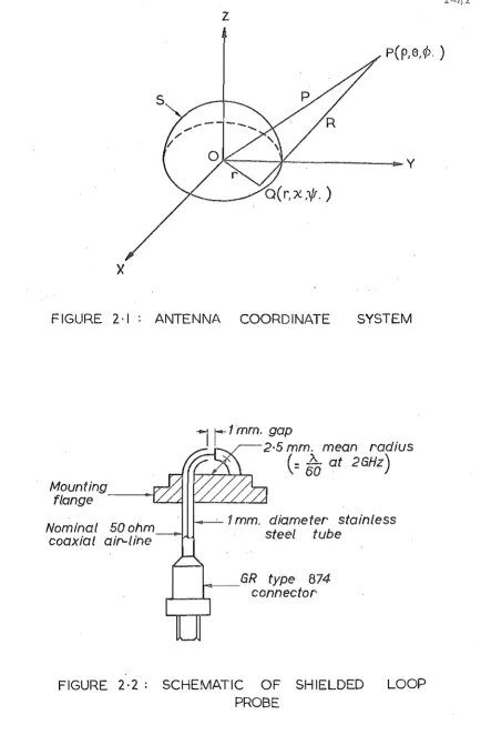
Consider an arbitrary antenna centred at the origin and totally enclose~ by .a surface S such that the region exterio.rto S is source free~ ;as in Figure 2010 T.he total field, at any point in a region can be. expressed i.nterms of the sources within
the
I region and' th.e values of the , ; •tangential components. of the fields over the boundaries
23 .
of the volume 0 Since the region exterior to
.s
1..Ssource free p the toj:al ";field from the ,antenna cem, be
completely specified in' term$ of the tangent;ial components of the fieldon BoThe field "On S gbeing pieoewis,e contin-uousg may be' represented exactly by a, complete D denumerably
infinite, set of orthogonal vector eigenfunctions24 0
Becau,se ·of the infinite ord,er of this field repregentation~ solutions to problems invo:l ving its use are. not generally amenable to purely analytical tec:;:hniques~' S.uch problems D however,u :can be sol vee!,. by applying approximation :methods on high speed digital computers,o The set representing the fiE?ldis truncated to. approximate the true field. on S , t o within .a 'prescribed er~ bbun.dp by
N
1-17
where g(r,x,~) is the approximation to the true field on S, An are the complex amplitude constants, !n(r,x,w) are
orthogonal vector eigenfunctions, and the coordinates (r,x,w) describe S.
Two representations having the form of (2.1) will be considered: one in terms of spherical vector modes for arbitrarily shaped antennas, and the other in terms of waveguide modes of prop~gation for the par~icular class of aperture antennas.
~) Arbitrary antennas .
.For an arbitrarily shB:ped antenna the most convenient form for the enclosing surface S is a sphere, with the fields on S represented, via (2.1), as
a
set of spherical vector modes 25. Th ese vec or mo es represen t d ' " t a 11 wavescrossing S, whether inward' or outward travelling with respect to the 'antenna. In the present case the region exterior
to S is . source free implying that only those modes .correspond-ing to outward travell.correspond-ing waves need to be considered.
Therefore, the. electric and magnetic fields at any point p, coordinates
E(p,S,~)
-n
H (p,S,~)
-n
(p,S,~), on S are given by
N
= I: [a
emn ~mn(p,S,~) + b emn !!emn ( p , S , ~) ]
emn 0 0 0 0
( 2 • 2)
0
N
=
JE..
I: [a' n (p,S,·,;,) + b . m .... (p.S,,;,)] (2.3). W )l . . emn -amn . 'f emn -awn ' 'f "
where the a and b are the suitably ordered complex modal
errm emn
o 0
amplitudes of the transverse electric (TE) and transverse ,
magnetic '. (TM) spherical vector modes m and n 0 respecti
ve--enID -Brnn
o 0
lyv given in Appendix 10 The radial f~nctions included in
this representation are spherical Hanekl functions of the second kind which satisfy the radiation condition at inf1nitY0 A
complete knowledge of the modal. strengths at one point in a region is sufficient to specify uniquely the fields everywhere in the regibno ConsequentlYF the modal amplitudes in (Zo2) and (20 3) specify the fields everywhere exterior to S to
the same accuracy as the fi~ld representation on So ES.timates of the fields interior to S are li~le to be less accurate since the effects of the neglected higher order modes become
increasingly more significant as the an.tenna is approacihedo. Equq.tions. (20 2) and (20 3) ,may now be considered as the electric
and magnetic field representations at any field point P(p,B,t) on or exterior to S~
The fields E and H are dependent upon the 2N complex -n .,....n
coefficients a and b
, enID emn For a pract.ical antenna if although
o 0
the func;:tional forms of the vector modes will·be known/i their relative strengths are l~kely to be unknowna Byperforrning independent field measurements of both, magni t,ude and phase of~n or!!rr' a set of linear independentllalgebraic equations is obtained in the unknowns a
emn o
and b emn o
These unknowns may be conveniently ,solved for by arranging the set of simu.1taneous equ<;l.tions in matrix forma Thus
D.
~
= [
j
E. 0 A"
where U
i is the ith element of the column matrix [uJ and corresponds
ith field point,
to thefieldme.as uremen t performed at the and H .. is the .
(i;~
j) th element of the square1J '
matrix [H J which gives the fun.ctional variation at the i th field point of the jth mode, w.hG)seamplitude is given by A., the j th elemen.t of the columnmat.rix [AJ Q Implici t in
J
(204) are three scalar"matrix ,e.quations corresponding to the three spheri'cal componen,tE; .. 0.£ the measured field~ From
!
a computational point .of:view,.i:b: is desirable to achieve
such separation by' consideJ:i;ag .±he field· component-by-componento Standard numericalmethods,e±ther matrix inversion or iterative techniques 26 g permit a .urrique
s.e~.ution
for theAj in (204) provided [HJ is non~singula.ro Once these coefficients have been determined, the' total ra&i.a .. tion patterQ of the antenna can be predictedo In particular,. measurements· performed in the near-field. can be operated . i ; em computation,Uly to ·infer the total radiation from' the antenna.
(b) ,Apertureantenn'a'~
A generalelectromagne:tic field can be completely expressed in terms of an electric vector potential and a
magnetic vector potential27. For the special class of aperture antennas i t is convenient to consider the surface S as part of the aperture plane:.' Consideri!1g' the field' onS and
I · h . I '. , . I 28"
by the aperture antenna is found to be the same as that produced by the equivalent, magnetic current sources in the apertlJre plane, alone. I f the ,tangential ele,atric field. in the ,aperture, plane, external to the aperture, is zero as is the case for aperture antennas mounts,din infinite, perfectJ,y conducting ground plane~., then t;he, equivalent
magnetic current sources exist only over. thec.apertu:te region" Thus the radiated field.can be fully spaci-fied by an
elect~ic vector potential expressed in terms 'of., the tangential electric field in the apertureQ
The aperture fields of an aperture antenna mounted in a ground plane can'pe represent.'ed'
py
a ,complete set of wave-guide mode,s of propagationsuital;:lle, to the geometry. In general, this set must include bothTEand TMmodes to,exp,ress the fie1dfully,o From· (2.1) and,.applying. the boundary condi tions on the electric fie.lds." ,the tangential ~lectric field on S for such ·an antenna is given by
Et,(r,*),= ,Z[A,. Z'XE .
- , n ~TE
n . n
(r ,.lj!) + Bn Z x ~TM (r, 1jJ) ] , n
(2.5)
where (r,lj!) are cylindrical coordinates in .the aperture, Z is the z direction unit vector normal to the ,aperture plane, the An .and
Bn
are'tne ordered complex modal amplitudesrepresenting the relative strengths of ,the ,waveguide., modes , and !2.TE (r,ljJ) and ETM (r,i)J) are theapert;,.ureelectric field
n
n
Introduce an electric vector potential·Ku such that scalar Helmholtz equation is satisfied by. the rectangular components of ~. given by
1
J
f
-jkR
F
=
.-
p (xpy)L -
dSUg
x
TiT
Rsa
1.
f
r
..,.jkR e . F
-2i
. Qex
l' YL
"'1'f'""""
dS U g: yJ
S u ,
whereP(xI'Y) and.Q(x,Y)prespecz:tively,are the x .and y direction components of the tangential electric· field :,in
e-jkR
the aperture l' . is the scalar. Green u s function· for unbounded, spaqe with, the. source and observational
coordinat~sde fined in Figure 2,; 1, andS U is the aperture 1-21
domain, 'a sub-domain of~ So By s~sti tuting ,the rectangular components:of (2Q5) into (206) and (207) a:p:dtransforming F. into sphericC\.l components; the fields radiated by .the antenna cap. be determined in spher;i,cal components l'via
E
=
-\-0 'iJ x Fand-, H =
..i,..
['iJ"fJ°F + k2FJLOll - =- .
-
- '
where'!.. is the vector differential. operatOL , Separation of tile· functional. dependence of the. sourC;:e coordi l1 a tes from that of the 'observational coordinates inth~ Greenus
GreenU s fUnction in terms of scalar sphericaJ, harmonics
g
-jkR . ( 2 )
e ... '.
=
~jk-00 j£ (kr)hQ,. (kp) for r ~ p
L (2Q,+1)PQ,(COSY) (2
Q
lO)
Q,=O JQ,P' h£ " (k ) (2) (k . .... r) f or r > p
where y ~ r g p p and R a+,e defined in Figure 201 p j Q, (kr) and h (2) (kp) are spherical Bessel and Hankel functions g
Q,
respecti 'lTely 0 .andP Q, (cosy) -are Legendre polynomials
represemting zonal hq.rmonics ~. This :expansion. separ.ates .the-, radial coordinate varia,tiDns'of the source point and the , , ; I ' '
obsex:'Vation . point? Anapplic.at.ion oftb.eL~gendl?e polynom-ial addi tion theorem29 ffl which is equivalent to expressing
tl:1e . zonal harmollics in terms of tesse,ral harmonics 9'
,
tra,nsfprms the field _expressions (from (2Q
8)
and(2a 9) )into forms mo,re suitable for the a,nalytic9-l integration over the:azimuth:al coo:):"diita.i;si Conl?idering, the fi.el,d
components indiv:idually·aYld·imposi:pgthe appropr;Lateboundary cQndi tions on the. gro\lnd plane 0 .the' field variations
of the remaining' components (normal, e:lec~ric and taIlgential magnetic field componen ts) are' of the. form,
(20,11)
where U (.p iI
H
is:. the field comppnentp the VQ, (p 0 41)· are the.functional' va~iations or modes .. of t1:1e 'field component in
"
.,
. , ,the, exterior region desc~ibed by
the
coordinates (p 0 ~) 0'variat-1=23
ions' but characteristic of theexi:erior· modes D . Furthe.r;morev . the· a,Q, are known' functions. of ,the modal amplitudes in{2o 5) D As beforeg . perfermi:r.g a series of independent field
measure-ments on the field components enables' a matrix equ?iti.Qn simi1-ar to that implicit in, (2" 4) to be derived,from a sui.tably truI).cated . form' of ,(2 D 11) 0 The matrix [H] now contains the
functional forms, of the exterior modes from (2011) v . and the column matrix [A] contains thea,Q, . coefficients as elements 0 Once these coe.fficients have been dete;r:mined> by numerical solution of the matrix, equatioIi 9 ' ;the t,ota1 ,radiation pattern
of the aperture anternamay be,dedllcedo 2022 Separability.of.fie1d valuesD
A unique solution for themoda1coe.f;Eieients ,in., <-204) or (2011).is 'possible i f and,on1yif .. thematrix [HJis non"", singular" This imp1ies'tl:lat,notonlymu~t the near;""'field mei\isurements of~theelectric' or magnetic . field component,be' linearly independenti: but also the ef.fects· of all. the modes in the exterior region must be separab:;Le D~ To sati,sfy. the'se . reqllirement$ i t iSi sufficient., to perform the measurements· along cE;l,nstant, coordiriat;ecurves:in one.' plaDe:o 'rhus iJ .
separation of t~e a~imu~a1 an~ularvariations ,of the' mode.s is ,ensured by performing the measurements at fi,eld, points w.ith a constaI).t radial coerd,inai:;e b since for.differEHlt
m()de indices· thea~imuthal modes are mutually orthogonal,,· Simila;rly ~measuring at field points wi th • constant~z:imutha1 .
\
variations of the field expressionsp due to the
orthogonality. conditions on the radial modeso
Consideration must also be given to the separability of . the TE mode.sf.rom, the TM mode,s in the spherical
vector mode field'representationo When performing" .. the' measurements, <;I.sQutl;i,ned above gtwo o~ the. three
orthogonal curvi).inear coordinates (p 17
e
d) p necessarilyassume coris,tant values 0 From the forms for theTE and ,TM
vector modes u ,given ·inAppendix IQthe.modal va~iati,.ons
in the remaining coordinate, for modes ,of one type (,TE OJ;, TM) u become' linearly dependent upon s,t.mil~r index',
modes -of the. other typeo For examp1.e g a, conside:r.:atioI1 of 8 componen 1:.s. of TEand TM modes for constant ¢ ,and 8
values' (that is u' measurements performed to separ:at?. radial
variation~) u shows that the rac;1~al vari.;:lt.ion of tb.e . .!I'M, mode ,of :r;adial mode indexn, -is a lineal;, comqi:nati.on of TEmodes of' rfidia:I" ~ode irid;ic~s, (n-l). an~,«rl7l)o'·. Conseq':lently~ (202) and (203) are'rearrangedsothat all modes with the same functio~al depenqenc~ on tJ:!.e field"
variat:i,on coordinate for ,each ,particuli;l.r set of ,measurements
, , . i ' , \
are grouped together-o leadillg to.the rEl~de£inilfg of "all
the modal ,coefficients in (26·4)? AS a result. afthe ." measurement, patternQ . these derived coefficients ,are
independent of :the field, variat.ion coo+.din~te- but are
1-25
the modal ampli tuCies 0 The Y'ejoY'e.iJ the fiB ld of .t.he an teny?a
can not .heinfe Y'Y'edsimp ly: f:('O/11 . a kno.wZ edge of. th~se
cae ffi oi-6ntsde Y'ive d fY'omne /ill'" fi·e Zd me as uY'emfBnt$pe Y' fo.Y'me d
on a singl,-e field. component. Since for different· fi~ld
components theuerived coefficients have different·
functionald~pendences.on.themodal- amplitudes p the
unknown amplitudes can be- determined by measu~ing two field-, components and solvipg the double set of sj.;m,ul,talleous
equations.~ The tal1gential·component.s of the. electric and magnetj,c fields are dependent· upon po:ti"l;TKand TM modesi:.whereas tl1.eradial: components ar.e functions of tbe TM modes, only "Me9-stirements' performed .. onthe~ .electric or magnatic radial component ca,n be usedf "theJ:efbrep to determine· the. sub-set 'of; the b
emn 0]:' a~mnmodal.,;amp:Litude.s p
o 0
respectively. This 'sub-!:)et tqgether wi th· computations on measurements of. a~y other field ,component .yielq..s the
complete .. s.et of modal·amplitu.des; AltJ:lOugl;1. thesearnplitudes. may b~ derived. from m.easu:r:ements p~rfOl;:med.on· the two.radial
problems i.n t1:1,e wav~guide mode field repre.?entation for aperture antennas" I.tmight be· thought th.,at (2" 11) could be rearranged into the· fO.rm
N
=. ): [A S (p Q <p) + BnTn (p u <P) ] n ' n n
where the: An and, Bn are as in (2 05) gand. theS
n (p viP) andT (p h <p) are ·the f"'!.llcti.onal variations of .the TE and
n • ' n
TMn waveguide ID0des in· the exter~.Qr .. regiqno Determina.tion of ~.t,he modal amplitudes wouJ,.dthen fo1.1ow directly f:J:;om tb.e nw:nerical solution of a' matrix equation ,as above'<> ,Further. investigatioureveals, .hpwever u that th,e matrixcontaini:pg
the· Sn (p ,<p)and T
I1
(p g.<P) as elements, is 'either analyticallysingular or numerically so ill:-con'dit;ioned that .. a reliai<Jleg ·.
accurate solution for the modal a~pli tudes is. not possible 0
As in ,.the' ca,seof the vector mode representat,ion p . i t is more
accurate to solve for.deriveq.·coeffic:ientso which. are functions··ofthe mGdal amp.li.tudes.o
2~ ~3., Fieldmeasurem!";l!n't.s a
From" (204} pto solve forN complex ,modal. coefficientsp.
Trunca,tion of the set of eigenfunctions representing the field tO'an upper mode'indexN as in (202)0 ··(203),and.(20S) results; in.2.N functions being included in the. representation (I , implyingtb.at ,the matrix equation derived from (2Q
4)
is of..
order 2N o' .Combinip.g the simi lar index modes· of . G:!ach . type'
(TEaI),d 2!Mi) WLth the same functionCiI variations.i.n the exterior: re.ga.on ~ and defining new· coefficients which are known .. functi:0I).s 'of the. respecti Ve moda,! amplittldes o reduces
the matrix equation .to order Nfor all· field c.qmponehtsa . Henceg , .numeri6aJ. solution of an N order matrix, equation
derived f.I;om<N .complex i:n,dependentmeasurements;·;o.fa field componentg yields a .set of N complex coeffi:cien,ts:r which
in conjunction with the set. of Ncoefficients cOIllputed from measurements Performed on; another field C0mpQnentg~' permits the requtre.d2N modal amplitudes to be det.erm:Lned-o:·'
To sunu:.ua:t.ize Qde1:;erminq.tion ·of,the 2Ncomplex, modal· amplitudes. appeari~(l in the modal field, representationS
(2.2) 11 (2, • ..3·)·d and ,(2.5) g, requires a total of:,2N- complex
independentfiel¢l measurelTlEantspthat is' N'co:roplex' measurements for, each of the two field components 0 Since these modal
amplitudes'c.ompletely.specifythe field raqiated by the
antenna ,to within the acctlracy limits:i,ltlPosedby the truncation of the field .representation 1'. 2N complex measurements of' th~ near-field p.attern are sufficient to infer 'the total
203 Source field distributions.
It is well known that th,e aperture field distribution and the far-field radiation pattern of ~ planar aperture
antenna form a Fourier transform pai"r21o
A.
compl~te
knowledge of one in both 'magnitude and phase over all regions of space, therefore,. uniquely defines th~ otheL Estimating,theaperture ,field distribution requires a complete knoWledge of the radiation, pattern, but .in practice this information is like~y to be incQmplete, since theradia,tion pattern will be known or measured only over the ,visible region of
30
space A meaningful approximation to the aperture field of an ant,enna with a nar,row beam radiation pattern, can be inferred by assuming ,the pattern fUnction to be ,negligible
I ,
in the invisible region . However, for a wide, beam ant~nna , or an array antenna, the pattern fU,nction is not negligible in ,the invisible region , in which the square of the magnitude, of the pattern function is a ,measure of the reactive energy
d . . d th' ,,31 b
store,l.n the near-f,l.el, of , e antenna '~ It has een 21
shown , t h a t the, radiatio,n pattern of a planar aperture antenna is an analytic fupction, and can be analytically continued from the visible region into the invi,sibleregiono Therefore" provided the rp.diation pattern ,is accurately
known wi thin the visible region, ,analytic continuation
can be, used to specify completely the pattern function over both visibl~ and invisible regions. The aperture jield .distribution can be determined)Jy Fourier transforming
1-29
By applying the N .F. T. f the complete far-field pattern
of an antenna can be inferred to within the accuracy limit imposed by .the field representation (2.1). Fourier
trans-forming the field pattern in both visible and invisible regions of space then gives an 'estimate of the, equivalent aperture source distribution. HoweveJCp this estimate is likely to be error sensi t i ve, because the higher' order modes f
which are neglected in (2.1), contribute ma.inly to the reacti,ve energy stored about the antenna, and they have a greater effect on the pattern ftinction in the invisible
region than in the visible region. Even when a pattern function is known accurately in the visible region, its analytic
continuation into the inv~sible region will in general be very 30
difficult to compute accurately , because such a computation is equivalent to extrapolation outside the measurement
interval. The Fourier transform method is useful in that the equivalent aperture sources so determined (effective current line sources) are the' sourc,es whose effects in thefar.-field are of the most importance.
An alternative approach, for aperture ,antennas is to solve for the modal amplitudes in the waveg'uide mode field representation (2.5) using the modal coefficients in (2011) I which have been determined by applying the No F e To, The two sets of coefficients are related bya matrix equation
where the column matrices [1\,J and [aJ contain as elements the modal coefficients in (2.5) and (2.11), respectively, The elements of the square matrix [G] are the functions describing the dependence of the field on the modal indices in (205) and (2011)0 Provided the matrix [G] is non-singul-ar the amplitudes of the waveguide modes can be determined from the numerical solution of (2 13)0 As with the
Fourier transform method, this 'techn.ique can give an
estimate only of the strengths of the modes whose effects are significant in the exterior field region.
204 Error analysis.
The accuracy of the N.F.T. is limited by ,two factors: the approximation that the pie.cewise continuous electro-magnetic fields can be rebresented by a finite set of eigenfunctions, and the accuracy to which the near-field of the antenna can be sampled.
2.41 Truncation error.
The truncation of the set of eigenfunctions is justified since the £ield representation is uniformly
convergent except at physical discontinuities on t.he .antenna. Increasing the order of the approximation,
N
p i.n (2 •. 1)1-.31
associated.with the solution of the matrix equation,
in particular, is greatly increased, because the number of numerical operations necessary to invert a matrix is
proport,ional to the cube of the order of the mat.r:ix. However, in practice the choice of N is govemced almost en rely
by consideration of the accuracy of the field representation.
An electrically small antenna radiates most strongly in 'the lower order modes f with the higher . order modes contribut,ing significantly to the total field only at points very close to theantennao For widebeqID antennas of t.his type, only a. limited number of modes are necessary to repres,ent. the far-field accurately I and the order of the matrix equation
is restricted accordingly. Due to the efficiency of standard numerical techniques for solving matrix equations and the restricted order of the equations encountered in the analysis of these antennas, the computationa,l'effort'required by
the N.FoT. is considerably less than for a complete
mode-by-mode., analysis of the three-dimensional near:-field as would be necessax::y in the th,ree-dimensional method of
1 ~
Brown and Jull as fO,rmulated, by Jensen'" 0
2 0 4,2 Fie~d sampling er!:'o~
To ens.ure adequate signal strength and sensitivity-for the detector, a practical probe must have a finite size. It has been shown for electric probes32 that provided the probe is electrically small (that is, tne probe length is much less than a .quarter of a wavelength) , . the scattering of the sampled' f.l,eld by the' probe will be negligible. Similarl:Yf the perturbatiDn of the field caused by a magnetic probe will be small provided the loop diameter. is well below a quarter of' a wavelength. A small magnetic probe responds to the electric field component that is
parallel to the plane of the loop as well as to-the magnetic field component linking with the loop. To sample the
magnetic field only, the loop ·must be either extremely s.mall (diameter less than a hundredth of a wavelength) . or
. 33 34
shiel(jed • It has been shown 'that due to the "antenna effect" an unshielded probe a tenth of. a wavelength in diameter responds·, equally, to the electric field component as to th.e magnetio field component •.
Radia,tion and., soattering effects caused by the
1-33
of .the ground plane by .a small probe penetrating the ground plane. Consequently, by placing all th.e de~ection equipment ,beneath the ground plane, the only dist,urbance to the field is caused by the measuring probe itself.
The field component being measured varie.s across the finite extent of the probe, with the result that the. probe ,rather than sampling the' field at a point.!', averages
the field valu~ OVer a small but,finite.region of ,space. This causes a small error in the .field values assumed in (2.4) or (2.11) 0 The order of magni tu,de of these
errors can be estimat~d by integrating the field component acrO$s ,the effective aperture of the probe and comparing with the ,actual field value at the field point. For example, consider: an ele,ctric probe sampling the ES
field component on the grounq plane. The sampling error reaults from the variation of-the Es component with
elevation a~gle S, and from the ,Vector and scalar spherical mo.de representations ·for E S' theS dependence resides
entirely in t~eLegendrefuncfions. In fact, because of the boundary conditions on the fields on the surface. of the ground plane, Es dep~nds only on the Legendre
m functions. of the form P
m
[ aP m+.2S!. (cos8) ] err
ae
8="2
=
0, (2,14)the functions of low order and degree are slowly
varying as8approach~~ TT /2 . Moreover, the uniformly
convergent forms of the field representations mean that for a.wide beam antenna only these lower index functions contribute significantly to the sampling error~
Assuming 'that the modal amplitudes qetermined by the
N.F.T. are accurate, the magnitude' of the percentage error is estima teq from the scalar mode i represen ta.tion for E 8 '
by summing the ,integrations of the P:+2S!.(cOS8) functions over the effective length ot: the sampling pr:obe,and . . " . i compcaringwith,the value,ofE8 at 8=,
1T/2.
T.he-.samplingerrol;' int~.oduced by an electric probe a thirtieth of a
wavelength long, opl?fating at ,a frequency of 2GHz,
and lqcp.tedata field point on the ground plane aguarter
of. a waVelength di~tant fr,om tl;le aperturer:im_of a. circuiar waveguide aperture antenna (the near-field sampling
point closest to the antenna in the .measurements
reported .in Chapter 4), has been estimated by this method as less than 1% of the actua.l fi.eld 0 '
In a similar manner a loop probe measuring the
1~35
the probe. The error introduced by a shielded loop
probe sampling the H . p component is caused by the variation of H p across the aperture of the probe. This. variation is given by the .dependence of H on the angular field
p
coordinates
e
and ~. In common with the Ee component discussed above, thee
dependence afH is given byp
m
Legendre functions of the form Pm+2.Q,(cos8), whereas the ~ dependence is determined by the form of the source field. For the previously quoted example of the circular aperture antenna, the radial ma:gnetic fi~ld component in tne aperture varies as cos~, since the antenn~ is excited in the. dominant waveguide mode. Therefore, by symmetry, H . . p. in the regionexte.rnalto the aperture
i
also varies as cos¢, and from the vector ,mode field representation, the 8 d~pendence is of the form
P
2n-l (cos8). In,tegrating, these . functions over the probe aperture A and sllmming
the
modes, inc1uded-in ,the field representation givesf
r
cos~. ~
C2n -'1J n
A . .
I
=
where th. eC2
n-
. I are· coefficients from the..
.
.
H p field representatiQnderived from theN~F"T. By expressing,
d d
cos¢
=
, and cose
=
(2. 16 )where d
=
;\/4=
the radius of the field point), applyir).g the binomial theorem, and neglecting terms in smallquantities raised to powers higher than the second, the magnitude of the diff~,rence between (2.15) and the value of H at the field point is found to be less than 0.5%0
p
The same method ,can be applied to determine t~he sampling error caused by a finite sized shielded, loop probe measuring the H¢ component on the ground plane. However, a more
serious source of measurement error results from the response of the probe to. the electric ,field. Th~ shielded probe
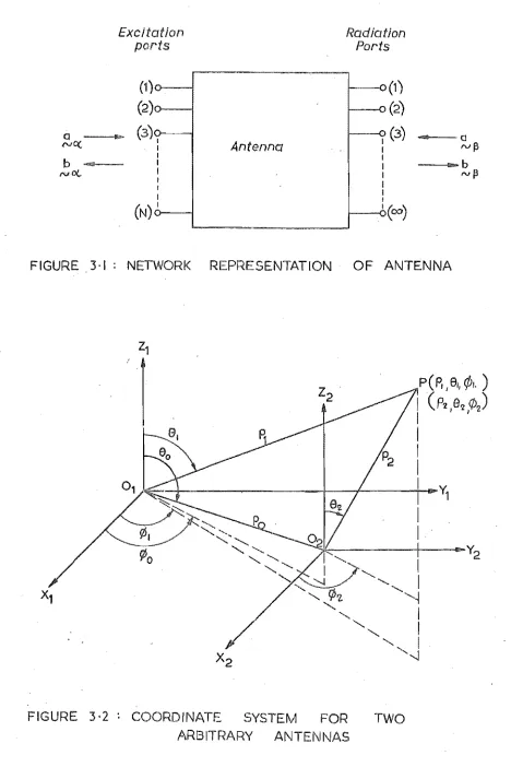
considered is shown in Figure 2.2. This probe i.s of standard d eSlgn . 33 Wlt . h a slng e turn . 1 ( . or lnner conductor ) an d an
unbalanced shield tomatcl;J. the ,unbalanc~d coaxial feed line of 50 ohms nominal characteristic impedanc80 A. probe of this type, wi th a mean radius of 5mm and, an, Oliterconductor diameter of Imm was constructed and found to have 'adequate sensitivity. Although the shield of this probe 'eliminates any coupling
with the'electric field compQnentperp~ndicular to the ground, plane, the probe may" respond to the tangential electric field cbmponent' parallel to both the plane of the loop and ,the
ground planeo This tangential component necessarily must be ' zero, on the, ground plane r but' may increase rapidly at .pOiJltS
1-37
field components are ·affected by spurious responses due to tangential components of the electric field. In the measurement of the H component of the circular,
. p .: '
aperture antenna discussed above., the only electric field component present.atthe field points where H· is sampled?
p
is the E component.
¢ Since
E¢
is normal to the plane of the loop, the measurement of Hp for this particular antenna is not affected ,by the presence of the electric field·. Conversely, the. measurement of H¢ on the ground plane ,is sensitiv~to the electric f~eld, as both the Ee and Ep components are present at the field points .wll.ere H¢ is sampled,and .are alignedparallel"j:o th~ plp,neofthe loop. The shielding of the probe eli,Ihinates the
responsedu~ to the Ee co~ponent, so that only the
E cqmponerttcauses the.measurement error in the sampling
p
The ma,gnitudeof this error can 'be estimated by 'integrating the.E.
comp~nent.
arc,und the p'erimeter.. p , "
of the loop. A simpler but more approxim~te approach
. .
is·· to considerthe::;;ection of the .. loop t.hat issubstant-· ially parallel to E as acting like ,an electric
p.
d ' 1.pO e 1 34 mh .1,: e magn1.tu eo"·· . d f th e va 1 tage ~n . d uce, d ' l.n the probe 'by H¢ ,~S . g1.Ver . . ' b 35
¥
V
where A is the area of the loop. The voltage generated in the probe by the electric field.is
v
=
Eh , E p ewhere he is the.effective length. of the probe parallel to E and is.assumed to be 0.701 x loop diameter .as a.
p
first approximation. An estimate of the significance of the V
E signal is given by comparing (2018 ) with (2017) 0 For the circular aperture antenna the ratio of E to H~
p
was evaluated at the .field sampling point closest to tne antenna by assuming that the modal amplitudes in the·. vector mode representations·for these. components, deter.mined
by the N .FoT. were correct.· Thus, V;E was found .to be .less than 3% of V
H whi.ch is the signal· i t is desired to measure < 2.5 Cri tiqU'e of the· N. F .·T.
The N.F.T. may be summarized as follows. The fields of the antenna are expressed as a set of orthogonal,
vector wave functions i or mode·s, whose, relative amplitudes are derived, from a limi.ted number of near-:, field measurements 0 Provided these field measurements are linearly independent the matrix equation relating the set of measurements to. the fi.eldrepresentation can be solved by numerical methods for the unknown. relative amplitudes of the modes.
Once de.termineq., these amplitudes. together with :the
1-39
In conunon wi ththe Fourier series method of. Brown
and Julil and the matrix' formulations of tl:1e three .... dimension-al extension ot' this metllOd3, the ,desired accuracy of
the field representation governs the number of ne,a~-field measurements required, since the determination of, N complex modal amplitude$ requires·a set ofN independent complex equations derived from N·complex field measuxements.
Because; a knowledge of· the relative amplitudes of '. the modes. in the field representation is sufficient to specify
the .radiation patt,ern'of::thei'antenna, only. relative measure-· ments of thenear-field-pattern.are necessary. Thus,
accurate calibration of the sampli:n g probes is· not· neces$a;ry unless 'measurements are: required of both an electric· and ,a mf!gnetic field component. In this . case, the two Sets of field me.asurements must ber;elated . to
each, other ,.-implying. the need for· calibration of each probe • The cietermination- ofN modal amplitudes, in9€;l1eral~
requires the'nllmerical solut,ion of, two matrix equations of order N/2, . since field· measurements must. be performed. on. two field components as aconse.quence of. the ,inclusion of the TE .and TM subsets of modes in the fielo.. representat-ions.. When comparec;1 'with. the.solutionofa matrix
computational effort and; time involved. (see Section 2.43). Furthermore, upon comparison wi th . the Fe,urier series ..
method and more especially th,e' auto-correlation method of Hamid22, the No FG T
~
reguiresless'computation~
.Afurther advantage of theN.F.T. is that the complete t~rE;!e-dimensional radi;ation pattern is inf,erred.fro:m linti:f::.ed near-field rite as,urements ,performed in one plane only, as
compared with the measurement .of the near-:-fieldpattern over a tbree~dimensionalsur'face enclosing, the antenna in .the
, ,
, , h' d' , I" h d 3,20.
prevlous t,ree-:-' lmenSlona met 0, S ' . 'This iS,of practical importance foranten,nas, mountE~d ab.ove" ground planes". since their· raqiation patterns can' be- inferred fr:om near-field measuremen ts performed by a small probe" penetrating W,e
ground-,plane. With the detection'eguipmentplaoed below the , ground plane the disturbance of the field is minimised.
For the special class of aperture antennas/whose aperture fields may. be 'represented in terms of, a !;let of waveguide modes ofpropagatioI} suitable to the pal;'ticular geometry: of the antenna, the, NoF.T. enables an estimate tq be made'of the higher order modes present in the aperture . . Finally,
the No Fo T._ is more suitable for inferring tl}e fa+:-field'
p~tterns' of a wide beam anteima than for ,an antennawi'th a narrow beam- radiation pattern. The latter requires .. a
z
~----~---y
x
FIGURE 2·1 AI\ITEI\INA COORDINATE SYSTEM
Mounting
flange - - t " " [
Nominal 50 ohm
coaxial ai~line
1
r
1rnm. gapr -
2·5 mm. mean radius(=
to
at 26Hz)1 mm. diameter stainless
steel tube
1-o-_6R type 874 connector
FIGURE 2·2: SCHEMATIC OF SHIELDED LOOP
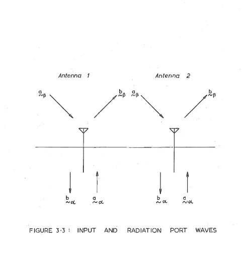
[image:51.582.77.511.31.693.2]Chapter 3 : Scattering matrix approach to the study of mutual coupling.
3.1 Introduction.
In recent years ,considerable attention has been directed at the ,design and analysis of array type
4-6
antennas • The performance of an array is de.termined partly by the array geometry and partly by the characterist-ics of the individ~a1, radiatinge1emertts. Because of the I mutua1coup1iilg effects of the surrounding elements the behaviou~ of a particu1~r element in a~ array environment may be markedly different from its behaviour as an isolated antenna. Moreover, in an electronically scanned array, since the coupling effect$ vary with the phasings of the e1ementexci tations ,as the radiation beam of the array is steered OVer the scan volume" the ,element and array characteristics vary with scanning. Before an accurate description of the performance of an array can be
developed, theJ;:"efore
i
i t is necessary ,to evaluate the effectsofmut;:ua1 .. coupling in the arr.ay.The earliest-mutual' coupling studies, were concerned
. . . . 36 h
wlth pal.rs of dlpo1e aIftenIfas. Carter formu1atedt e induced emf' method to .derive the se,l f and mutual impedances of two ,identical parallel dipoles in broadside, collinear, and echelon configurations • The radiation re.sistance off
1-43
who first introduced the unit, cel:L concept~ The driving point and mutual impedances of two similar thin wire dipoles
d ' d b . 3 8 . . 0 1 t '
were eterml.ne y Kl.ng uSl.nga current lntegra equa :Lon technique. By this technique King was also able to comput.e. the current distributions and radiation patte,rns of tl;1e
dipoles. Allen etc aL 39 , i n a series of stud.ies ,inves'tigat-ed the coupling effects in large dipole ,ar:r:ays mount,inves'tigat-ed
over ground planeso The method used to.calculate the coupl-ing effects was based upon the impedance formulae originally developed by Carter. By applying a bidimensional Fourier,
40 series for the fields in terms of plane waves, Stark , derived expressions for the radiation resistance and
reactance of a.dipole in an infinite array backed by a
ground plane. This approach extended the results of Wheeler by including the reactance of the array and allowing