Under Seismic Loading
A thesis
submitted in partial fulfilment of the requirements for the Degree
of
Master of Civil Engineering in the
University of Canterbury by
J. L. Wallace
ABSTRACT
The results of an investigation into the performance of reinforced concrete beam-column subassemblages containing lap spliced reinforcement in the potential plastic hinge region of a beam are presented. Two specimens were tested with simulated seismic loading.
One specimen complied with the New Zealand Concrete Design Code, NZS 3101: 1982, except for the placement of the lap splices. The second specimen contained beam reinforcement details from a building constructed in the early 1960s.
Current concrete design codes specify lap splices should not be placed in beam potential plastic hinge regions where inelastic reversing stresses are possible during seismic events. During testing the transverse steel specified for the confinement of the lap splices was unable to prevent bond deterioration between the spliced bars once inelastic bar strains had developed at one end of the splice. The failure of the lap splices led to a loss oflateralload capacity and a low level of ductility from the specimen.
Reinforced concrete buildings designed to pre-1970s codes may be considered inadequate when viewed in light of the provisions in current codes for seismic design. The testing of beam details taken from one such building indicates insufficient anchorage existed for the plain longitudinal beam bars in the joint. The loss of bond for the plain bars began in the initial load cycles of the test and led to a lack of specimen stiffness and lateral load capacity. The presence of the lap splices is considered to have accelerated the loss of bond from the bars.
Acknowledgments
The author would like to thank. the Earthquake and War Damage Commission for the EQC research funding used to complete the testing.
The efforts of the technicians Mr Norrie Hickey and Mr Gavin Hill during the construction and testing of the specimens were appreciated.
Post-graduate student MrS Hakuto was helpful during the testing programme with advice and for information on the test rig.
Supervisors Mr Bull and Professor Park kindly gave their time to discuss aspects of the project and reviewed the chapters of the thesis. Their contribution to the project is gratefully acknowledged.
CONTENTS
1.0 INTRODUCTION 1
2.0 LITERATURE REVIEW 3
2.1 Introduction 3
2.2 Bond and Anchorage 3
2.2.1 General 3
2.2.2 Bond Resistance 3
2.2.3 Anchorage 6
2.3 Bond Stress Slip Relationship 7
2.3.1 General 7
2.3.2 Bar Slip during Cyclic Loading 7
2.4 Review of Existing Structures 8
2.5 Lapped Splices 8
2.5.1 General 8
2.5.2 Longitudinal Reinforcement 9
2.5.3 Concrete Strength 10
2.5.4 Splice length 10
2.5.5 Cover and Splitting Patterns 11
2.5.6 Loading History 13
2.5.7 Transverse Reinforcement 14
2.5.8 The Effect of Shear Force on Splice Placement 15
2.5.9 Summary 17
3.0 LAP SPLICE CODE REQUIREMENTS 19
3.1 Introduction 19
3.2 Code Requirements for Splice Length and Location 19
3.2.1 General 19
3.2.2 Development Length for Deformed Bars in Tension 19 3.2.3 Development Length for Deformed Bars in Compression 21 3.2.4 Splice Placement and the Development Length for Plain Bars 21
3.3 Transverse Steel Code Requirements for Lap Splices 22
3.4 Review ofNZS 3101: 1995 23
4.0 EXPERIMENTAL PROGRAMME 25
4.1
Introduction25
4.2
Specimen Design25
4.2.1
General25
4.2.2
Specimen One25
4.2.3
Specimen Two29
4.3
Specimen Fabrication31
4.4
Materials32
4.4.1
Concrete32
4.4.2
Reinforcing Steel33
4.5
Test Equipment33
4.6
Instrumentation35
4.6.1
General35
4.6.2
Measurement of Displacements36
4.6.3
Measurement of Strains37
4.7
Testing of Specimens39
4.7.1
Loading Pattern39
4.7.2
Testing Procedure40
5.0 TEST RESULTS AND OBSERVATIONS 41
5.1
Introduction41
5.2
Test Results of Specimen One42
5.2.1
General42
5.2.2
Observed Behaviour42
5.2.3
Load-Displacement Response46
5.2.4
Beam Behaviour49
5.2.5
Column and Joint Behaviour60
5.3
Test Results of Specimen Two64
5.3.1
Observed Behaviour64
5.3.2
Load Displacement Response66
5.3.3
Beam Behaviour70
5.3.4
Column and Joint Behaviour79
6.0 DISCUSSIONS AND CONCLUSIONS 85
6.1
General 856.2
Behaviour of Specimen One 856.2.1
Specimen Performance 856.2.2
Splice Performance 876.3
Behaviour of Specimen Two90
6.3.1
Specimen Performance90
6.3.2
Bond Considerations for Plain Bars91
6.4
Conclusions93
APPENDIX 95
NOTATION
Ab area of an individual bar, mm2
f . 2
Ag gross area o sectwn, mm
As area of non-prestressed tension reinforcement, mm 2
Asp area of flexural reinforcement provided, mm 2
Asr area of required flexural reinforcement, mm 2
Atr smaller of area of transverse reinforcement within a spacmg s crossmg plane of splitting normal to concrete surface containing extreme tension fibres, or total area of transverse reinforcement normal to the layer of bars within a spacing, s, divided by n,
2
mm
c the smaller of cc or cs, mm (NZS 3101: 1982)
cc distance measured from extreme tension fibre to the centre of the bar, mm (NZS 3101:1982)
c m the smaller of the concrete cover or the clear distance between bars, mm
cs the smaller of the distance from the face of the concrete to the centre of the bar, or half the centre-to-centre distance of bars in the layer, mm (NZS 3101: 1982)
For splices, cs was the smaller of the distance from the concrete side face to the centre of the outside bar, or one half the clear spacing of bars spliced at the same location plus a half bar diameter, mm
db nominal diameter of bar, wire or prestressing strand, or in a bundle, the diameter of a bar of equivalent area, mm
f' c specified compressive strength of concrete, MPa
fy
lower characteristic yield strength of non-prestressed reinforcement, MPafy
1 lower characteristic yield strength of transverse reinforcement, MPahe column depth parallel to longitudinal beam bars being considered, mm
ktr an index of the transverse reinorcement provided along the anchored bar, Atr fyt /1 Os, expressed as mm (NZS 3101 :1982)
Ld development length, mm ( ld , NZS 3101 : 1982)
Ldb basic development length of a straight bar, mm 0db, NZS 3101 :1982)
n number of bars in a layer
n
L number of ties provided within Lds maximum spacing of transverse reinforcement within Ld , or spacing of stirrups or ties or spacing of successive turns of a spiral, all measured from centre-to-centre, mm
Vi ideal horizontal load capacity of the specimen
a
8, ab, ac, ad, ae parameters used in determining development lengths for straight
reinforcing bars
INTRODUCTION
The limited lengths in which reinforcing bars are available make it necessary to link the bars for the construction of most reinforced concrete structures. Reinforcing bars may be welded together or use a form of mechanical coupling, but for economic reasons two bars are often simply overlapped for a distance to create a lap splice. The transfer of forces from one bar to the other is completed through the concrete surrounding the bars.
In earthquake-resistant reinforced concrete structures, sections of members may have to endure large deformations during severe seismic events. In these sections, known as potential plastic hinge regions, damage to the concrete will be inevitable.
As the performance of lap splices is dependent on the condition of the surrounding concrete, present building codes require lap splices to be placed in regions where the integrity of the concrete will be maintained. Previous codes were not as strict on the placement of lap splices and in older reinforced concrete buildings they may have been placed in areas now recognised as potential plastic hinge regions.
This project examined the behaviour of two beam-column subassemblages containing lap spliced reinforcement in a beam potential plastic hinge region. These specimens were constructed for simulated seismic loading tests to investigate the performance of the specimens and the lap splices.
The first specimen complied with the New Zealand Concrete Design Code, NZS 3101:1982, except that the lap splices for the deformed longitudinal bars were placed in a beam potential plastic hinge region. The behaviour of the lap splices and their influence on an otherwise ductile reinforced concrete design are presented.
deficiency may be found in early structures reinforced with plain round bars. Present design codes specify plain bar anchorage lengths to be twice that for deformed bars.
The object of the second specimen was to review the seismic capacity of beam details from a building constructed in the early 1960's. Two details of concern were: plain round longitudinal bars lap spliced in the potential plastic hinge region of one beam; a relatively small column depth in comparision to the ratios required in recent design codes for the column depth to longitudinal beam bar diameter. The effect of these on the behaviour of the specimen is discussed.
CHAPTER TWO
LITERATURE REVIEW
2.1 INTRODUCTION
The relationship between steel and concrete in reinforced concrete members is examined with a discussion of anchorage, bond and bar slip. These factors are reviewed as they have a role in lap splice behaviour.
Previous research on lap splices is surveyed with particular reference to loading conditions simulating seismic actions.
2.2 BOND AND ANCHORAGE
2.2.1 General
Satisfactory performance of reinforced concrete structures requires composite action between the reinforcing steel and the surrounding concrete. Bond stresses along the concrete-steel interface modify the steel stress along the bar length by transferring force between the bar and the surrounding concrete [6]. Two distinct situations lead to the formation of bond stresses in reinforced concrete members:
(a) Anchorage or development bond stresses are required in the end region of bars to transmit the bar force to the concrete.
(b) Flexural bond stresses occur along a bar due to the change in bar force as a result of variation in bending moment along a member.
2.2.2 Bond Resistance
Classic bond theory describes three components that contribute to the bond stresses on an embedded bar:
(a) Chemical adhesion (b) Friction
Bond for plain round bars depends primarily on the first two elements. Once sufficient force is applied to break the adhesion, the bar slips relative to the surrounding concrete. Further bond can be developed only by friction between concrete and steel and the wedging action of small dislodged particles.
Deformed bars depend primarily on the mechanical interlocking of the ribs or deformations, that stand proud above the surface of the bar, with the surrounding concrete to provide bond capacity. The bond capacity of deformed bars is typically superior to that of plain round bars. Figure 2.1 shows three types of stress associated with the bond strength of deformed bars:
(a) Shear stresses Va developed through adhesion along the surface of the bar. (b) Bearing stresses fb against the face of the rib.
(c) Shear stresses vc acting on the cylindrical concrete surface between adjacent ribs.
~---c---~1 b ~
di, db di,'
Nominal
diameter~
Figure 2.1 The Stresses Between Two Ribs of a Deformed Bar [1].
140
psi Circumferential concrete
120 stress at bar - ...__ _ _ ~
100 Bond
Longitudinal concrete
80 stress at bar
7
60~=---40
20
-20 LRadial concrete
stress at bar
-40
Longitudinal
[image:13.595.117.473.81.339.2]Ordinate,z/0
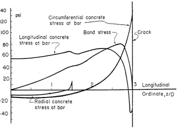
Figure 2.2 Longitudinal Variation of Stresses in a Concentric Pull-out Specimen, at fs
=
6.9MPa [4].
The following three effects were noted:
(a) Circumferential tensile stresses caused by bonding forces near transverse cracks can
start radial (splitting) cracks.
(b) Longitudinal tensile stresses at the concrete-steel interface can form internal transverse
cracks.
(c) Radial tensile stresses resulting from dowell action of flexural reinforcement can
prevent contact near the crack and allow separation and slip of the bar.
Bond strength is affected by the quality of the concrete immediately surrounding the
reinforcing bar, which can be influenced by its placement relative to the reinforcing bars.
Water gain, sedimentation and aggregate segregation under bars results in a localised zone of
concrete that has compression and tension strengths reduced below that of the main body of
the concrete. Bars in the top of concrete elements with more than 300mm of fresh concrete
cast beneath [2] are expected to gain greater amounts of air and water beneath them. Their
bond strength will be less than that for bars placed lower in an element. This effect is offset in
codes of practice by requiring an increase in the anchorage length for bars in these conditions
2.2.3 Anchorage
Stress from a deformed bar is transferred by a combination of direct bearing and wedging
action between the reinforcement ribs and the concrete. The resultant force can be broken into
components parallel and perpendicular to the reinforcing bar axis as shown in Figure 2.3.
(a) Bond Force on Bar
I • • '~ •: I • I ' .- .. I
-. '
( c l Components on Concrete
( b l Reaction on Concrete
...
·...
0 • . . ~·~·' 0
(d) Tan~entlal and Radial Components
Figure 2.3 Forces Between a Reinforcing Bar and the Surrounding Concrete [5].
The bond component is responsible for the change in bar force. The radial component
induces a circumferential tensile stress field in the surrounding concrete. Longitudinal cracks
form along the axis of the bar when the tensile stress exceeds the tensile capacity of the
surrounding concrete. If splitting of the concrete cover occurs and spalling results, effective
anchorage ofthe reinforcement is prevented and a bond splitting failure follows [16].
When reinforcement is discontinued in a member, the length of embedment between the free
end and a critical section is called the 'anchorage length'. Anchorage of straight lengths of
deformed reinforcement can fail in one of two ways:
(a) The concrete key (see Figure 2.1) between the rib deformations can fail in shear (often
called 'pullout').
(b) The concrete surrounding the bar, can split longitudinally, parallel to the bar axis,
The first failure mode usually occurs with relatively short anchorage lengths or when significant confinement or volume of concrete around the bar is present. The second failure mode is called bond splitting [16] and is the most common for anchored bars with usual transverse steel contents, concrete cover thicknesses and anchorage lengths.
2.3 BOND STRESS-SLIP RELATIONSHIPS
2.3.1 General
Unless the strain of the concrete and steel is the same and constant over a length, a deformed bar will attempt to move or slip in relation to the surrounding concrete. Initially chemical adhesion and mechanical interaction prevents slip. As the load is increased, adhesion is lost and slip occurs, the ribs of a deformed bar restrain the movement by bearing against the concrete. In the case of plain bars, friction provides the resistance to slip once adhesion is destroyed.
Cyclic loads with a low number of stress reversals commonly represent seismic loading actions. The following section discusses slip in relation to this type of loading for deformed bars.
2.3.2 Bar Slip during Cyclic Loading
For deformed bars under cyclic loads, concrete strength, geometry and spacing of deformations, cover, bar spacing, and the amount of transverse reinforcement play a large role in the bond-slip behaviour .
T [N/mm2]
15.--,---,---r---~--=-~~
---CONFINED
IO
-t=r~GION
5 v %
-5 -10
___________
,.---MONOTONIC LOADING
...
-IS '---:---'---J._----...1,_----___j_~
-z
-1 0 2s [mm]
Figure 2.4 Bond Behaviour Under Low-Cycle Loads [6].
2.4 REVIEW OF EXISTING STRUCTURES
Research projects (36, 37) completed at the University of Canterbury Civil Engineering
Laboratory have tested specimens representing existing members designed to earlier New
Zealand concrete design codes. Bridge piers and columns each with plain round bars for
longitudinal reinforcement have been tested with simulated seismic loading to examine their
performance. These specimens lacked adequate bond between the plain longitudinal bars and
the surrounding concrete. The column specimens (3 7) experienced significant softening of
the lateral load-displacement relationship during the first cycle to three-quarters of the ideal
lateral load capacity. The column units displayed a relatively low capacity to dissipate energy
and a large reduction in strength by the end of testing. The available structural ductility
measured for these specimens was between 2 and 2.5.
2.5 LAPPED SPLICES
2.5.1 General
The fundamentals of bond, anchorage and slip have been discussed in previous sections.
They are crucial factors in the behaviour of lapped splices.
Two bars placed side by side forming a lapped splice are in effect two anchored bars. A
in the surrounding concrete along the splice length. The bar forces being transferred generate
shear stresses and splitting forces in the surrounding concrete. Adequate bond along the bar
surfaces and the ability of the concrete to transfer shear without excess deformation is
essential for a lapped splice to function satisfactorily.
Early testing of lapped splice performance was conducted under monotonic loading
conditions. Since the late 1970's reversed cyclic loading conditions simulating seismic action
has revealed significantly different lap splice behaviour. The Department of Structural
Engineering at Cornell University appears to have been first to investigate this area [21].
They continued and have contributed much of the knowledge on this subject [13,15,16,18,23].
A number of parameters have been found to have significant influence on the behaviour of
lapped splices. A survey of the literature is presented under these headings.
2.5.2 Longitudinal Reinforcement
The adverse effect of increasing bar diameter on bar anchorage has been known for some time
[7]. Larger bond stress concentrations can be expected with larger bars as the ratio of
cross-sectional area to bar surface area is directly proportional to bar diameter. Longer anchorage
lengths for increasing bar diameters can offset this. The use of larger diameter bars results in
an increase in the size of the cracks that can develop along the bar length. These cracks act as
points ofweakness which tend to initiate any eventual splitting failure. Tests have shown that
it is almost impossible to avoid a splitting anchorage failure for bar sizes greater than 50mm
[9].
In evaluating the performance of splices the actual reinforcement strengths that need to be
developed during severe loading conditions should be considered. Yield stresses appreciably
above the nominal design value and enhanced strength through strain hardening have been
found to prevent a ductile response in members containing lap splices because of splice bond
failure occurring before the bar reached yield [1
OJ.
Applying a safety factor to the lap lengthusing a steel stress 25% above reinforcing nominal yield strength was found to be inadequate
2.5.3 Concrete Strength
Cracks are formed in concrete when tensile stresses, induced by bond action, exceed the
tensile strength of the concrete. It has been shown that these cracks develop further with
increase in steel stress, causing bond deterioration and ultimately preventing force transfer
between concrete and steel [12]. The tensile strength of concrete is usually considered to be a
function of the compressive strengthf'c, and is generally less than 0.2/'c [1]. On this basis,
bond strength will improve with increasing concrete compressive strength.
Results from monotonic load tests show diminishing increases in splice strength with
increasing concrete strength until a compressive cube strength of concrete around 70 MPa [8].
Concrete strengths beyond this had a negative effect on splice strength. Shrinkage of the
concrete accounts for some of this, as shrinkage increases with increasing quantities of
cement. Restraint of the shrinkage in the vicinity of the bar results in tensile stresses in the
surrounding concrete. These tensile stresses are superimposed on bond stresses around the
reinforcing bars [8].
Another reason for the reduction in splice strength is the greater stiffness of higher strength
concrete. This leads to poor bond performance when high localised bond stresses are unable
to be redistributed effectively [8].
The ability of concrete to redistribute stress is reflected in recommendations for the seismic
design of lap splices. For higher strength concretes, shorter splice lengths were preferred with
small stirrup spacings to encourage an even redistribution of bond stress near failure [13].
Concrete strength is considered to have a relatively minor role in the behaviour of lapped
splices under simulated seismic conditions. Its influence over the onset of concrete splitting
in monotonic loading is reduced in seismic conditions where considerable concrete damage
may occur before failure [24].
2.5.4 Splice length
Research into splice performance under monotonic loading conditions has shown increasing
splice strength and reduced average bond stress with increasing splice length [7]. For splices
without transverse steel an upper limit on splice length was found beyond which there was no
increase in strength [14]. Later study found the use of transverse steel allowed further
Orangun et al [5] developed an expression for the bond strength of embedded and spliced bars using regression analysis of published data. Development and splice lengths were found to be equal and provisions were given for their reduction with enhanced confinement from increased concrete cover and larger quantities of transverse steel. The data base for this study, however, was limited to specimens that were tested under monotonic loading and that failed prior to yielding of the main reinforcement.
The relevance of equal development and splice lengths for cyclic loading conditions was discussed by Gergely et al [15]. Tests at Cornell University had shown that this was valid for splices with relatively little confinement. These splices failed when one spliced bar began to lose its anchorage as stirrups yielded at the splice ends. Splices with sufficient confinement, particularly during repeated loading situations, experienced a redistribution of forces well before failure. Yielding of the spliced bars led to splitting of the surrounding concrete. Progressive yield penetration during the repeated loading reduced the length over which one spliced bar could transfer forces to the other. Bond forces became almost uniform in both spliced bars, superimposing the radial bursting forces and requiring a splice length greater than the development length. A minimum splice length of 30 bar diameters was suggested for splices designed to resist a limited number of cycles beyond yield.
Finite element analyses completed at Cornell University verified the assertion that spliced bars require greater bond lengths than single anchored bars with equal amounts of confinement [16]. The authors considered shorter splices (30-40 bar diameters) demonstrated superior performance because they displayed more favourable redistribution properties.
Research conducted at Canterbury University [24] concluded that long splice lengths did not prevent splices "unzipping" due to gradual yield penetration during cyclic loading.
2.5.5 Cover and Splitting Patterns
,cb
~---~----~ ~
Ct,>Cs
i:
c =c,=s/
2= 2Cs
. I
Cs>Cb
1
1 C=Cb
Cs»CbJ
'
I
I
I
Failure Patterns os for Sln~lt Bors. 1
I
Just bef.orEIIFoilure
Side Split Failure ~l
l
I
l
, - - - i
1
I
At Foilure C
5»Co
v-Notch
Failure
At Failure
c,
> CbFact-and-Side ~it
Failure
Figure 2.5 Failure Patterns in Lapped Splices [5].
Analysis of results from monotonically loaded spliced bars led Orangun et al [5] to conclude that the limit between pullout and splitting failure is a cover distance to bar diameter ratio c/db of about 2.5 [5].
Concrete cover plays a less significant confinement role for splices subjected to cyclic loading compared to those loaded monotonically [16,18,24]. The considerable cover cracking before failure led the Cornell University researchers to believe that cover resistance was an unreliable factor. Provided that the cover did not suppress a longitudinal splitting mode of failure, it was not a consideration when developing a model predicting splice :Strength. A minimum clear cover of 1.5db was found to be sufficient for load transfer requirements. All beams subjected to cyclic loading with splices located in a constant moment region experienced longitudinal bond splitting failures. Typically, side and bottom cover cracking lead to a corner cover spalling mechanism and the loss of force transfer between spliced bars [16].
2.5.6 Loading History
The application of many cycles of repeated loads, with loading applied only in one direction are reported to have little effect on the performance of anchored and spliced bars when the load level is below 70% of the ideal strength [8,19]. A few cycles of repeated load above 90% of the bar yield forces, however, rapidly increased the rate of bond deterioration in a splice [18].
The effects of stress reversals (loading cycles applied in both directions) with load levels beyond the ideal strength of lapped splice members was first investigated by Cornell University [15]. Beams containing lap splices were subjected to reversed loading and compared with specimens subjected to repeated or monotonic loading. The rates of cracking, damage penetration and strain increase were greater for the specimens with reversed loading. The number of cycles before failure was always significantly greater for repeated loading [15].
At Cornell University, researchers using reversed cyclic loading were unable to prevent longitudinal bond splitting failures for spliced bars located in constant moment zones [16]. Suggestions for design were based on splices sustaining a specified number of cycles in the inelastic range. A minimum of 15 to 20 reversed load cycles beyond the yield of the bar and a maximum steel strain (one-off) in the splice of at least 2.5 times the yield strain were considered as indicative of satisfactory performance. It was recommended that splices should not be used close to ground level in the first storey columns due to the high demands of plastic hinges in those columns [13].
The behaviour of compression lap splices under inelastic repeated loading was examined in beam and column specimens detailed to satisfy the above design suggestions [23]. Most of the specimens failed with crushing of the concrete outside the splice region after meeting previous criteria for satisfactory performance. A small number of changes to the original guidelines [13] were proposed. It was concluded that the design recommendations may be used for tension and compression lap splices subjected to inelastic cyclic loads [23].
2.5. 7 Transverse Reinforcement
Investigations by Tepfers [8] under monotonic loading conditions revealed increases in splice strength and changes in the modes of failure when stirrups or spiral transverse reinforcement was present. Whereas splices without transverse reinforcement burst in a brittle manner with little warning, the presence of confining steel resulted in a gradual method of failure. Stirrups spaced uniformly along the splice were found to be less effective than a number of stirrups concentrated at each end of the splice where bond stresses were largest.
According to the ACI Committee 408 (1979) provisions for development and splice lengths [20] the maximum effective amount of transverse reinforcement of area Atr required for monotonic loading is
A1r _ 10.5db
s fy
mm
(2.1) where s = stirrup spacing,
fy
= the yield strength of the longitudinal reinforcement anddb= the nominal diameter of the longitudinal reinforcement.
A lapped splice in a beam provided with transverse steel satisfying Eq. 2.1 failed in flexure when tested under monotonic loading [21].
Further investigations involving reversed cyclic loading have concluded that the presence of transverse reinforcement reduces the propagation of longitudinal splitting, bar slip and to some degree yield penetration along the splice length. The presence of transverse reinforcement was also recognised as an important factor in bond-shear interaction. Specimens were detailed with up to twice the amount of transverse reinforcement required by Eq. 2.1. Generally stirrup strains did not reach yield in the most heavily confined splices and failure of the splice was delayed until damage of the cover concrete induced failure. An equation giving the recommended spacing of stirrups along a splice was suggested [16].
Research at Canterbury University during the early 1980s investigated the performance of lapped splices in column and bridge pier specimens under reversing cyclic loads [25]. Large amounts of transverse reinforcement were found to improve bond performance by limiting yield penetration into the splice region. Progressive longitudinal bond failure was sometimes prevented, and in those cases main bar fracture occurred during large inelastic displacements. The study indicated that lapped splices could be used in columns designed to resist severe seismic loads provided that the splices were not located in regions where there was significant yielding of longitudinal reinforcement [25].
2.5.8 The Effect of Shear Force on Splice Placement
Monotonic load tests indicate that a moment gradient has little influence on splice strength if the shear force is moderate. However, splices located in regions of high varying shear may not perform as well [5].
Investigations at Cornell University [16] into splice behaviour during inelastic cyclic loading included an examination of the influence of moderate levels of shear. Figures 2.6(b) and 2.6(c) show the details used for splices placed in regions of constant moment and regions of shear. When shear was present, damage and yield penetration was found to be confined to one end of the splices resulting in superior splice performance. Bond failure had not occurred when the loading was discontinued for some of these specimens. The amount of transverse steel provided for confining the splice was at least four times greater than the amount required to resist levels of nominal shear stress up to 1.73 MPa. To counter the effects of dowel action on the anchorage capacity of the spliced reinforcement it was recommended that the close spacing of the stirrups should be continued for a distance d beyond the high moment splice end, where d
=
the effective depth of the beam.I
I
t
.1.
.! .
I
~u I· 2.13 m 2.13 m 2,13 m ·I
(1) (b)
...,
,.,
.L
'"""
(Y' •30 ' ?l.
I
I
fk·l--·~·~,.j 89
64 I 38
25 mrn hor5
f
l~~.
t
(o)
I·
2, 13m 2J3m.I
(c)Figure 2.6 Beam Specimen Details (a) Typical Cross-Section (b) Splice in Constant Moment Region (c) Splices in Shear Region [16].
The depth of cast concrete has an effect on the bond strength of splices in the top layer of bars in horizontally cast members. These splices were found to experience more cover splitting than those with less concrete cast underneath the bars. The weaker concrete matrix surrounding the top bars and water gain in the top in easily workable mixes were recognised as contributing factors [18].
2.5.9 Summary
The performance of lap spliced reinforcing bars has been investigated in a number of research programmes. The literature review in this Chapter considers factors affecting the behaviour of splices under a variety of loading conditions. Reversed inelastic cyclic loading simulating intense seismic action, however, is of particular interest. The following conclusions have been drawn from the literature review:
1. Increase in bar diameter leads to a decrease in anchorage capacity for a given splice length, and is detrimental to splice performance during reversed cyclic loading.
2. Concrete strength has relatively little effect on the performance of lap splices confined by significant quantities of transverse reinforcement during simulated seismic loading, because of the considerable concrete damage before failure.
3. The development length for single anchored bars, determined from monotonic testing, is insufficient for spliced bars designed to resist a limited number of load cycles with the bars in the inelastic range. Additional splice length may improve the splice performance during cyclic loading. However, it will not prevent a longitudinal splitting failure if progressive bond deterioration occurs.
4. When large amounts of transverse steel are used to provide splice confinement in reversed cyclic loading conditions the role of the concrete cover in providing confinement is less important.
5. The amount and distribution of transverse reinforcement in a spliced region is an important factor for all loading conditions. Sufficient confinement will limit the propagation of longitudinal splitting along the splice.
bond deterioration along splices located in constant moment regions under inelastic reversing loads.
CHAPTER THREE
LAP SPLICE CODE REQUIREMENTS
3.1 INTRODUCTION
This chapter reviews some of the previous code requirements that relate to the placement and detailing of lap splices, particularly those from NZS 3101:1982 [2] to which Specimen One was designed.
Bond and anchorage provisions in the current code ofpractice NZS 3101:1995 [30] are briefly discussed to highlight the changes between the codes.
3.2 CODE REQUIREMENTS FOR SPLICE LENGTH AND LOCATION
3.2.1 General
Anchorage requirements in the previous New Zealand concrete design code NZS 31 01 : 19 82 [2] closely followed ACI Committee 408 recommendations [20] for development and lap splice lengths. Orangun et al [5] completed an analytical review ofdevelopment length and lap splice data from monotonic test conditions and gave equations for predicting anchorage strength. These were simplified by ACI Committee 408 to facilitate design usage and after minor alterations were adopted for the New Zealand code.
The New Zealand code NZS 3101:1982 [2] specified that the minimum lengths for lap splices in tension and compression were the development lengths for tension and compression, respectively. The development length of deformed bars was a product of the basic development length and any applicable modification factors.
3.2.2 Development Length for Deformed Bars in Tension
For deformed bars in tension the basic development length was
where Ab c
f'c
area of bar being developed, mm2
the smaller of cover parameters cs and cc, as shown in Figure 3.1, mm specified compressive cylinder concrete strength, MPa.
0
cs- The smaller value of either the horizontal cover plus O.Sdb or half the horizontal centre - to - centre distance between bars (ignoring lap splice pairs).
cc- The vettical cover plus O.Sdb.
Figure 3.1 Definition of Distances cc and cs.
Other basic development length equations allowed simpler calculations when greater bar spacing and cover was available and any reduction in development length due to transverse reinforcement was ignored.
The final development length ld for a bar was the resultant of the basic development length !db multiplied by modification factor or factors as follows:
(i) With reinforcement having a lower characteristic yield strength (fy) other than 300 MPa
fy
300
(ii) For top horizontal reinforcement with reduced bond quality due to more than 300mm of fresh concrete cast below the bar .
1.3
(iii) In members not resisting seismic load with reinforcement in excess of that for flexure, shrinkage and temperature requirements.
Asr Asp
c
where k
=
AtrfYt < dtr . lOs - b (3.2)
c+ktr
However the development length for deformed bars in tension was to be not less than 300mm.
The symbols used in the equations are also defined in the list of symbols at the beginning of the thesis.
3.2.3 Development Length for Deformed Bars in Compression
For compression splices the basic development length was
[Amendment No.1, December 1989] (3.3)
but not less than 0.040dbfj where db was the nominal bar diameter.
Modification factors could reduce this development length by a factor of 0.75 if sufficient transverse steel existed, and in proportion to reinforcement in excess of that required by analysis provided it was not a detail required to resist seismic loading.
The length of a lap splice in compression was not to be less than 0.067 fydb for steel with afy of 430 MPa or less, (0.12fy- 22)db for afy greater than 430 MPa, nor 300mm [Amendment, No. 1, 1989]. When the specified concrete strength was less than 20 MPa the splice length was to be increased by one-third.
3.2.4 Splice Placement and the Development Length for Plain Bars
development length for a plain bar was twice that of a similar sized deformed bar and not less than 24 bar diameters for a plain bar in tension.
Earlier New Zealand codes of practice [27,29] recognised that lap splices should be located away from points of maximum tensile stress. This was encouraged by specifying increased lap lengths when large percentages of the tensile reinforcement were spliced or in conditions of high steel stress. NZS 3101:1982 [2] set restrictions on lap splice placement in members designed for seismic loading. To ensure reliable anchorage for longitudinal beam bars, no portion of a lap splice could be located within a beam/column joint region, or within one effective depth of the member from a potential plastic hinge region.
Bundled bars were able to be lap spliced with increases in lap length of 20% for a three bar bundle and 33% for a four bar bundle. The increases allowed for reductions in the exposed perimeters of the bars. Bars larger than 35 mm in diameter could not be lap spliced.
3.3 TRANSVERSE STEEL CODE REQUIREMENTS FOR LAP SPLICES
Transverse reinforcement in potential plastic hinge regions of beams serve three purposes:
(i) Prevent the buckling of longitudinal bars in compression. (ii) Provide confinement for the concrete in the compression zone. (iii) Act as shear reinforcement.
The New Zealand code, NZS 3101:1982 [2], had the following transverse steel requirement for lap splices in beams and columns. Tensile reinforcement was not to be spliced in a region of tensile or reversing stress unless each spliced bar was confined by a stirrup-tie so that
Atr ) dbfy
s 48fyt [Amendment No.1, December 1989] (3.4)
Lap spliced column specimens tested in accordance with the above equation were found to support at least 85% of the ideal column strength in at least 20 cycles of reversed loading. These splices were found to sustain a few limited cycles beyond yield [28].
3.4 REVIEW OF NZS 3101:1995
NZS 3101:1995 [30] contains refinements and design simplifications which have been developed since NZS 3101: 1982 was released. Changes relevant to the requirements discussed previously in this chapter are revisions to the clauses for bond and anchorage. Some of these revisions are discussed here. In Appendix I both the previous and present equations are used to calculate the length ofthe lap splice of Specimen One.
Deformed reinforcing bar is to be used for all non-prestressed longitudinal reinforcement unless there is a special reason for using plain bars.
The equation for the development length of deformed bars in tension is based on a combination ofthe recommendations of ACI 318:1989 [33] and recent research into the bond strength of deformed bars [32]. This equation includes a factor for the depth of fresh concrete cast beneath the bar. A lower value for the development length may be obtained if a further three factors are considered. These factors account for: any additional concrete cover or clear distance between bars, transverse reinforcement perpendicular to the bar, and excess reinforcement provided in a flexural member not subjected to seismic forces.
Within specified limits the relevant development lengths remain the minimum length for lap spliced deformed bars in compression or tension. The amount of transverse reinforcement required for a reduction in the lap length in spirally reinforced compression members is redefined.
The anchorage requirements for plain bars in tension are revised with hooks specified for their development. Lap splices for plain bars require the hooks to be located at right angles to the concrete surface when the concrete cover thickness does not exceed 50mm.
Lap splices are not to be used for any transverse reinforcement placed in potential plastic hinge regions.
3.5 SUMMARY
To ensure satisfactory performance from lap splices during seismic loading the current and previous New Zealand concrete design codes prevent splice placement in positions that are unable to provide dependable anchorage conditions.
CHAPTER FOUR
EXPERIMENTAL PROGRAMME
4.1 INTRODUCTION
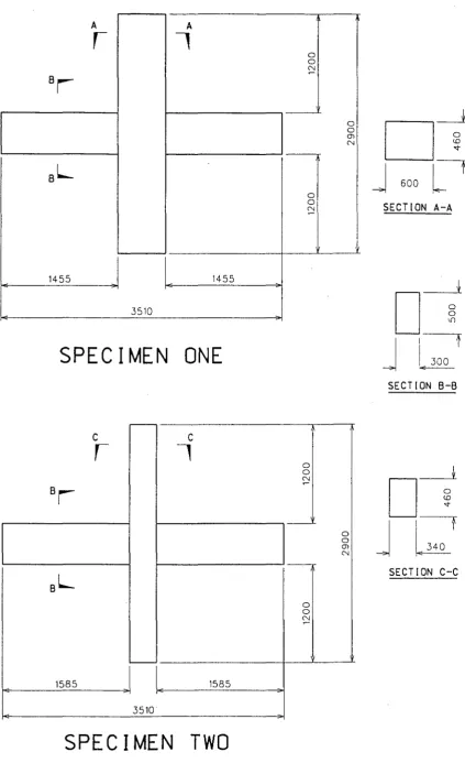
The two specimens tested were beam-column joint subassemblages. The longitudinal beam bars of each specimen were lap spliced in the potential plastic hinge region on one side of the column. The overall dimensions of the two specimens are shown in Fig. 4.1.
Specimen One was designed to meet NZS 3101 (1982) with the exception of the position of the lap splices.
Specimen Two was constructed to test beam reinforcement details from a building designed in the late 1950's (see Fig. 4.2). Beam cross-section dimensions and the longitudinal reinforcement (plain bars) were identical to those of the existing building. To prevent possible shear failure in the beams additional transverse steel was used. The column dimensions were kept close to the original size to model similar bond conditions for the beam bars through the joint. The beam longitudinal steel areas and cross-section dimensions of Specimens One and Two were identical.
4.2 SPECIMEN DESIGN
4.2.1 General
New Zealand Standard Code of Practice, NZS 3101 (1982) with amendment No.1, and capacity design methods were used in the calculations.
4.2.2 Specimen One
Deformed bars were used for longitudinal beam reinforcement. Four D24 Grade 300 steel bars (p= 1.37%) were used as top flexural beam reinforcement and two D24 Grade 300 bars (p'= 0.69%) were used as bottom beam reinforcement.
A
, ,
A 0 0 N8r
8L
0 0 ;:::!1455 1455
.3510
SPECIMEN ONE
;
-'
c
, ,
c
0 0 ;:::!
8r
----;sL
0 0 ;:::! 1585 ,~, 1585 .3510SPECIMEN TWO
Fig. 4.1 Dimension of the Specimens
0 0 (J) N I 0 0 (J) N
o-t
J
600[1
SECTION A-A
t
o---r~
I
t
~ .300
SECTION
8-8
t
J
q
§!
b
[image:34.598.65.489.54.748.2],_ ,_
,_ ,_
W SETS @ 9' 1229rrrnl"'
~
,_
....,Ar
li'@ 15" 1381rrrnlf-
-~ <>
1--
,_
f- 1-- ...JA
12'1305rrrnll 2'-6' 1762rrrnl
12" 1305rrrnl 1--
,_
12" 1305rrrnllB B
10-1" bars~
r
l
IE ~"""
]
-r
? f-,_
4-1" bars ('•.
l,l"tiesets/
r
"'
~ 0IL--~
- -
li' stirrup- ~Uw
='
L_j :...
2-1' bars
spliced----
-
, _SECTION B-B
SECTION A-A
EXISTING BUILDING
Fig. 4.2 Beam-Column Detail of an Exterior Frame from an Existing Building
Anti-buckling areas are based on the area of a single stirrup leg. The value should be doubled (in brackets) to enable a comparison with the other requirements.
The transverse steel used in the specimen met the required steel areas, while the anti-buckling spacing requirement was eased by 10 mm. This provided an area of transverse reinforcement which just met the shear reinforcement requirements, and minimised any addtional confinement. Double stirrup ties were placed at each bend of the cranked beam bars to restrain any buckling.
>liE
>'e
Oou~
ties Af
>I
{'<
_/'?
024 spacer/
L
180 145 A 485
024 bars
5 sets of R16 ties @ 65
NOTES:
)~,r
~
rr
rf
-. l _1-
..,
7-~
• ?? ~Ll
•.\j
. / ~
6-028 bars 4-024 bars
SECTION B-B
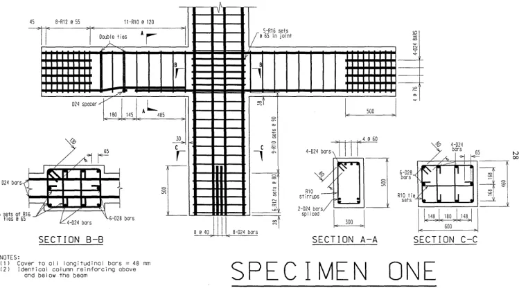
( 1 l Cover to all longitudinal bars = 48 rrm (2) Identical column reinforcing above
and below the beam
0 0 <.0
1r
~""
c
,
l/
1 5-R16 sets @ 65 in joint V>=
<=
..,. "'
=
IlV ..,.
-B
,
-;:: "" ~1
IE
J
..,.
500 g
"" V)
+-CD
"'
~Ill
(@
600
c
"f,
""' 4-024 bars~-0 ~I/
6-028}
=
bars"" 0
R10
-<
0
2 '-'"'
CD
V) t• - R10 tie
"' s 1rrups
r->:
:
sets c:r; 2-024 bars/u:>
sp I iced
~j
8 @ 40 _] Ill_ 8-024 bars
~i
%
~
IE148>\ E 180 J,148J 600
SECTION A-A
SECTION
C-C
SPECIMEN ONE
Fig. 4.3 Reinforcing Details for Specimen One
E
N
[image:36.848.73.822.54.470.2]Code requirements for the maximum diameter of longitudinal beam bars passing through interior joints (Cl.5.5.2.5 (b)) set a minimum column width which was used in the design. Six D28 and four D24 (Grade 300) bars were used as column flexural reinforcement. This provided an ideal moment capacity 97% greater than the beam overstrength moment demand.
Large amounts of horizontal joint shear steel (R16 tie sets) led to considerable congestion in the joint. The lack of an axial compression load contributed to this.
Table 4.1 Summary of the Transverse Steel Requirements for Specimens One and Two
Requirement Area required/spacing : Spacing required
Shear A /s
=
1.30mm2/mm s; 220mmv
Anti-buckling At/s
=
0.57 mm2/mm (1.14 mm2/mm) s; llOmm Splice confinement A /s tr=
1.00 mm2/mmSteel used in S 1 1.31 mm2/mm 120mm
Steel used in S2 0.71 mm2/mm 220mm
4.2.3 Specimen Two
The construction drawings of the existing building (see Fig. 4.2) were examined and Specimen Two was designed to match the beam details as closely as possible. Only the amount and spacing of the transverse steel was changed. Plain round bars were used for longitudinal beam reinforcement. Lengths of the laps and crank, and the number and type (Grade 300, R24) of longitudinal bars remained the same.
45 8-R12 @ 55 5-R10 @ 220
AI
305
I
AL
?
. :?
R24 bars
r
...!r.w·~""~·
5 sets of R16
~
ties@ 75 ___...~ 4-012 bars
SECTION B-8
NOTES:
(1 l Cover to alI longitudinal bars= 48 mm (2) Identical column reinforcing above
and below the beam
762
220
I
5-R16 setsV)
'-0
@ 75 in joint . 0
~
"" = I
HI!Yi
. . . ~8
,-~
_j'_ ""
!;j
lt±m
1-l
~
~1
""' I
= ..,_ 0 <.0 OU> CD -+
1... 500
J
"' "' I
=
""-~i
{
~i
"'II II<:
4
@
60 4-R24 bars-;\ ' - - - .
if-
~ ~/l~·
00
..,..,
~
R10 .,.-4
_,__I
Ill II1----'L;
2s-tRi;;u:a
5
r~
Ill
sp I 1 ced I 1
3 @ 55"'"' 7-024 bars
WW
SECTION A-A
SPECIMEN
Fig. 4.4 Reinforcement Details for Specimen Two
0
0
..,..,
8-HD24 bars
R10 tie set
0
=
SECTION C-C
TWO
w
half of the code allowance for gravity loading conditions. The maximum spacing permitted by shear requirements was chosen for the transverse steel. An arrangement that met none of the steel area requirements and exceeded the anti-buckling spacing conditions (as shown in Table 4.1) resulted. The first stirrup was placed the full spacing from the column face as in the existing building.
Bond conditions for the beam bars passing through the joint needed to be similar to those in the existing building. Eight HD-24 bars as column flexural reinforcement limited the column width to 340 mm (305 mm in the existing building).
Tie sets of R16 bar were used for horizontal joint steel and four D12 bars were required as vertical joint shear steel. Reinforcement details for Specimen Two are shown in Figure 4.4.
4.3 SPECIMEN FABRICATION
All longitudinal reinforcing bars were supplied cut to length and threaded or bent as required. The majority of the transverse reinforcement was supplied bent, some additional reinforcement was prepared in the laboratory.
Templates of the member cross-sections were used to construct the reinforcement cages. Wire ties were placed at every practical position to improve the cage rigidity during lifting.
The plywood formwork was oiled before casting to help strip the specimens. Spacers were placed in the bottom of the mould to ensure the correct cover thickness and the cage was lowered into the mould. Inserts were placed to allow lifting brackets to be attached. Figure 4.5 shows Specimen One ready for concrete placement. Concrete was supplied from a ready mix plant, it was placed with a skip and compacted by an electrical vibrator. Hessian was laid over the specimen and kept moist for seven days to allow the specimen to cure in damp conditions. The formwork was then stripped and the specimen was lifted to prepare for testing.
Fig . 4.5 Specimen One Ready for Concrete Pour
4.4 MATERIALS
4.4.1 Concrete
The concrete for Specimen One had a specified twenty-eight day compressive cylinder
strength of 30 MPa and a slump of 100 mm. A compressive strength of 25 MPa (at
twenty-eight days) and a slump of 100 mm was specified for Specimen Two. Twelve 100 mm
diameter x 200 mm test cylinders and three 120 mm x 120 mm x 360 mm test beams (for
flexural testing) were cast with each specimen . These were cured at 100% humidity and a
temperature of 20° C. The actual concrete properties are shown in Table 4.2
Table 4.2 Concrete Properties
Specimen One
I
TwoSlump (mm) 80 90
Age at test of specimen (days) 24 30
f'
r. at test of specimen (MPa) 32.0 31.8
4.4.2 Reinforcing Steel
Reinforcing steel test samples were either cut from the delivered lengths of bar or supplied cut to a suitable testing size.
Three samples of each bar size were tensile tested with increasing monotonic load in an A very Universal Testing Machine. An extensometer was placed on the bars for strain measurements over a 51 mm gauge length. Values of load, displacement and extension were automatically recorded during the tests on a computer.
The steel properties are shown in Table 4.3.
TABLE 4.3 Reinforcing Steel Properties
Specimen One Two
Bar D24 D28 R16 RIO R24 HD24 D12 R16 RIO
Measured fv (MPa) 313 318 325 325 318 434 365 325 340 Measured f11 (MPa) 471 481 479 474 469 581 513 471 491
(I) Also used as transverse beam steel in Specimen Two.
4.5 TEST EQUIPMENT
Figure 4.6 shows an elevation of the test rig and a specimen. Each specimen was positioned with end-plates over each beam and column end. Nuts tightened over each longitudinal bar held the end-plates in place. All the connections between the end-plates and the rig were steel pins which allowed free rotation at the member ends. Apart from the column base all member ends were free to move horizontally in the direction of loading.
A jack loaded the top of the column horizontally and was supported by a reaction frame placed to one side. The load was applied to the column via the steel pin through the end-plate. The restraining action provided by the supports at each beam end applied vertical reaction forces to the beams.
50mm dia. steel pin
50mm dia. steel pin
50mm dia steel pin
Test unit
Load cdl 75mm dia. steel pin
75mm dia. steel pin
~~
1334 ...~
1334 ...1-
1905 ...1 ..
1905.1
Fig. 4.6 Elevation of the Test Rig
50mm dia
steel pin
50mm dia steel pin
§
§
-0
V'l
Reaction Floor
w
Each beam end support consisted of two steel RHS sections attached via steel pins to the beam end-place and to an end-plate on the laboratory floor. Four electrical resistance strain gauges placed on a steel section enabled it to be used as a load cell.
Jack movements could be load or displacement controlled as values for both were available. A load cell at the end of the jack was connected to a Budd Strain Indicator. The column top horizontal displacement was registered by a linear potentiometer and displayed by a digital voltmeter. Calibration charts converted the microstrains and millivolts into kilonewtons and millimetres respectively.
4.6 INSTRUMENTATION
4.6.1 General
All load cells, linear potentiometers, electrical resistance strain gauges and clip gauges were connected to a 256 channel data logger computer.
Between increments of applied load or displacement (during a test) a scan was taken by the data-logger recording information from each of the channels.
Five load cells provided the values of forces applied during testing. One load cell was placed at the end of the jack, the remainder were on the support legs at each end of the beam. The latter four load cells consisted of four electrical resistance strain gauges on each leg wired as a bridge circuit connection.
Before testing commenced data and calibration equations were obtained for the five load cells. These had been generated by calibration tests using a Budd Strain Indicator, a data-logger and a 1000 kN A very Universal Testing Machine.
4.6.3 Measurement of Displacements
Linear potentiometers measured member distortion or travel and the movement of reinforcing
bars. Steel bars (10 mm diameter) internally threaded at each end, were placed through the
reinforcing cage between the sides of the formwork. Other small lengths of internally
threaded bar were welded to reinforcing steel. The bars projected outwards so the threaded
ends became flush with the concrete face. Lengths of 5 mm threaded rod were screwed into
the 10 mm bars and used to mount the linear potentiometers onto the specimen. Before the
concrete was cast short pieces of timber, polystyrene or plastic hosing were placed around the
10 mm bars . When removed they left space to prevent concrete bearing on the 10 mm bar
(and altering the readings) during testing.
Fig. 4.7 shows the arrangement of potentiometers recording slip in the lap-splice. An
estimation of the amount of slip possible was made and spacers were placed around the 10
mm bars to allow it.
A potentiometer with a maximum travel of 500 mm registered the displacements at the top of
the column. It was connected to a digital voltmeter which provided readings allowing loading
to be based on displacements.
Each potentiometer was calibrated before testing of a specimen began. Metal spacers of
specified thicknesses placed between the target and the potentiometer gave readings on the
datalogger to provide a calibration equation.
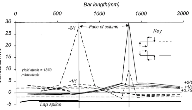
4.6.4 Measurement of Strains
Electrical resistance strain gauges were placed on longitudinal and transverse reinforcing to
enable strains to be monitored.
The placement of strain gauges was similar for both specimens. Both sets of lapped bottom
beam bars in a specimen were strain-gauged so as to minimise the effect of losing any before
or early in the test. One of the four top beam bars was strain-gauged. A set of beam stirrups
on each side of the column were strain gauged. Half of the longitudinal column bars were
strain gauged to provide strain information at the beam faces. A selection of the joint shear
steel and column transverse steel (near the joint) were also gauged. Positions of the strain
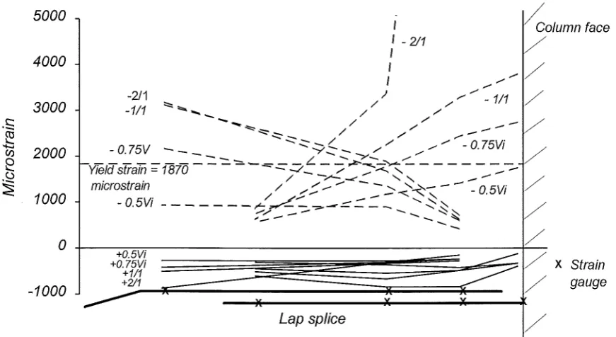
gauges placed on Specimen One reinforcing steel are shown in Figure 4.8.
Gauges were placed on the transverse steel in such a manner that bending strains due to
bowing of hoops and stirrups were not recorded. The gauges used were Showa 120 ohm foil
strain gauges with a 5 mm gauge length.
Reinforcing steel was filed, polished and swabbed clean before strain gauges were attached
with cement. Five or six coats of a waterproofing compound were applied before a small
piece of mastic tape was added for further waterproofing and extra protection during casting.
Slip of the beam bars was considered likely. To prevent the strain gauge leads to gauges on
the bottom beam bars for both specimens from being pulled from the gauge the leads were
folded twice just beyond the mastic tape. The folds were covered with shrinkwrap which was
heated. It was hoped the lead would gradually pull out of the sleeve as the bar slipped.
As the Specimen One longitudinal bars were deformed it was thought the deformations may
protect the gauge (by removing concrete ahead of the gauge) as the bar slipped. The plain
bars of Specimen Two gave the strain gauges no protection. Instead a small amount of a
flexible water sealer was placed in front of each gauge allowing a small area without concrete
to exist for the gauge to slide into.
Values for the amount of longitudinal beam bar area lost with the placement of the strain
gauges and polystyrene (to allow potentiometer rod slip) vary for each specimen in the joint
Ar
1\
-
~x" ~ • ~
-
- r-..•-,.
X X X
() <D
CD
() <D X X X,.,<D
()B
~ ~B
r
. - ,...,_,
-
~,....,
~
-~-...
X X r-...X X X~
X " X x.
.
~X X-
-
.
~ '-'•~L
I\_100Ll15C
~
50
1_1~
100
'-=- 160 -~ ~- 225 125 125
SECTION A-A
SECTION 8-8
X
CD
X
¢
t
X
-) )
<D
()~
X /
225 . 160
Indicates o stirrup or transverse
steel set contoing strain gouges.
See Sections A ond B.
Indicates the position of o strain
gouge on o column logitudinol bor.
Indicates the position of o strain
gouge on o longitudinal beom bor.
II
Strain gouge
Fig. 4.8 Position of Strain Gauges on the Reinforcing Steel of Specimen One
(.;.)
potentiometer rods lost 8% of the available bar area. In the lap splice region each bar of Specimen One lost 7% of the bar area. The maximum area lost from a beam bar in the joint of Specimen Two was 10% and 4% was lost from the area of the bars in the lap splice region.
Leads from the strain gauges were gathered together in bundles for protection during casting, and directed along the member to emerge around 600 mm from the faces of the joint core.
The strain gauges were not expected to last the entire test on Specimen Two. Six clip gauges were placed to reveal longitudinal beam bar strains in the joint and near the pinned end of both beams. One top and two bottom beam bars were instrumented. Gauges were connected between two internally threaded 10 mm bars welded to a longitudinal beam bar. A polystyrene spacer was placed around both before concrete was cast.
4.7 TESTING OF SPECIMENS
4.7.1 Loading Pattern
The specimens were tested in the cyclic loading pattern shown in Fig. 4.9. The pattern has been used in previous tests completed at the University of Canterbury for determining the performance of specimens in simulated seismic loading. The first two cycles of the tests were load controlled and the remainder were displacement controlled.
In the first cycle of loading the beams were taken to one-half of their theoretical ultimate load. The load was calculated on the basis of actual material strengths. The second cycle of loading was to three-quarters of the ultimate load and the corresponding column top displacement in each direction, /1+ and /1-was noted. The column top displacement for each direction at first yield was taken as
4
11y
= -
11- and3 11y
=
4jj.+
3
Displacement ductility factors in each direction were defined as
ll = /)J/1
y
>-f -_,
i=
u
::::>
Cl f -z LLJ -1
::>::
LLJ
u
<( -2
_,
a...
(/)
Ci
-4
-6
-8
Fig. 4.9 The Loading Pattern
4.7.2 Testing Procedure
Two scans were taken by the data-logger before a test began, a scan was recorded at every increment during a test.
CHAPTER FIVE
TEST RESULTS AND OBSERVATIONS
5.1 INTRODUCTION
This chapter describes the response of the two specimens to testing. Test observations, charts and photographs illustrate each specimen's performance.
Data is presented and the progress of tests are discussed relative to the ideal horizontal load Vi for the load controlled cycles, and the displacement ductility factor ll for the remaining displacement controlled cycles. These were defined in the description of the test procedure in section 4. 7 .I.
All photographs or charts in this chapter displaying a representation of a specimen will have the lap splice located in the left beam which may also be described as the west beam.
The performance of the datalogger during testing restricted the amount of strain gauge data that could be presented for each specimen. Several ambiguities were noticed in data recorded by the data logger.
If strain gauge readings for a datalogger channel were discontinued during a test (this was assumed to be the result of a strain gauge damaged by specimen deterioration) the remaining channels on the same datalogger section recorded unaccountable data readings. For the data scans in which the strain gauges were damaged, losses in tension strain or gams m compression strain were registered, often in unrelated sections of the specimen. As the true data readings for the scan were unrecorded, the remaining test data was unable to be corrected and had to be ignored.