University of Canterbury
Depa.rtr.oent of Corn.puter Science
Honours Project Report
in ..
2
I
A
lie
Simulation
Paul Reynolds
Supervisor R. Hunt
October 1 984.
"
t
s
This report describes a Simula progtam designed to model the
behaviour of
X.25
Public Data Networks and produce statistics on
various performance indices of the network. These include such
indices as:
- packet transfer times for each pair
ofnodes
- time spent in each node
- line utilisations
- wait times for each line
- buffer utilisations
The user descibes the network
by
suppling the model with
infotmation on each node and the lines that connect the nodes. This
Contents
1 Introduction
2 Model design
2.1 Design decisions
2.2 Simulation Program
2.2.1 ServerClass
2.2.2 NodeClass
2.2.3 Related Processes 2.2.3.1 TimerProcess 2.2.3.2 OutputProcess 2.2.3.3 Source
2.2.3.4 Submitter 2.2.3.5 Sink
2.2.3.6 Retransmitter
2.2.4 StatsCollecter
2.2.4.1 The collection procedures 2.2.4.2 The procedure Report
2.2.5 Initialise
2.2.6 Main Program
3
use
of the model3.1 The configuration file 3.1.1 Routing algorithms
3.2 Simulation times and seeds
3.3 The collected statistics 3.3.l Title
3.3.2 Number of packets created 3.3.3 Packet transfer times 3.3.4 Time spent in each node
3.3.5 Number of packets with errors received 3.3.6 Number of Retransmissions
3.3.7 Number of acknowledgements 3.3.8 Line Utilisation
3.3.9 Wait times for lines 3.3.10 Buffer Utilisation
3.3.11 Packets rejected due to lack of buffers
3.4 The Dump and Debug files.
4 An example of use
6 Conclusion
7 Acknowledgements
8 References
Appendix 1 Code of PSN, the model itself
l Introduction
The aim of this project was to develop a tool for the study
of the effect of different network configurations and routing
algorithms on packet switched network efficiency. The tool is a
Simula program which models the behaviour of Packet Switching
Networks (PSN). The model takes as input a configuration file
describing the nodes of the network and the lines between them.
It produces statistics on:
- packet transfer times for each pair of nodes
- the time packets spend in each node
- the number of packets with errors that were
transmitted between each pair of nodes
- the number of retransmissions that occured at
each node
- the number of acknowledgements between each 0 [,
pair of nodes
- the line utilisation (
- the wait times for each line
- the buffer utilisation at each node
- the number of packets rejected at each node
due to a shortage of buffers.
These statistics are useful for the intial design or in planning
extensions to an existing network. It was the interest expressed
by the New Zealand Post Office in obtaining this type of
information, for possible expansions to the existing PSN, that
prompted the initation of this project.
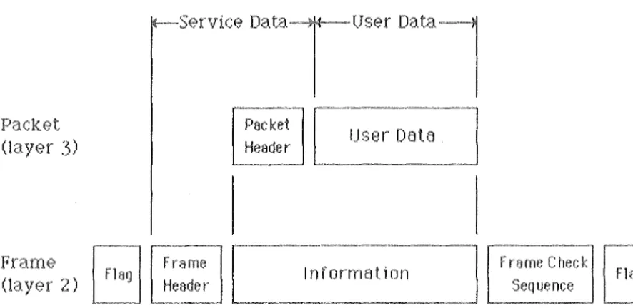
A Packet Switching Network is a data communication service
in which the information transmitted on the lines is grouped into
variable length frames which are separated by variable length
pauses depending on the volume of data being transmitted. Each
data frame consists of service data (to enable the packet to be
routed through the network and allow the detection of
transmission errors) and user data. (see figure 1) These frames
are transmitted independently across the network and are
regrouped by the network at the destination for transmission to
the receiving data terminal equipment (DTE). As a result, packets
from different terminals can travel via the same communications
channel thereby providing increased channel utilisation.
The user/network interface for a PSN is described in CCITT
standard X.25 [l]. This standard covers the physical, data link,
and network layers of the International Standards Organisation
Open System Interchange (ISO OSI) model [2] and uses a sliding
window protocol to handle transmission errors [3]. There is no
standard covering the internal protocols of PSN. However most use
some form of sliding window protocol at layer 2 (Data Link) to
handle errors and at layer 3 (Network) to impose flow control to
ensure that one terminal does not monopolises a line.
This report assumes that the reader is reasonably familiar
Packet
(layer
:3)
Frame
(13.}'E?l. 2)
Packet Header
[ Fla~ [;ra me ] ,_, ______ -'
Header _n ·f-o.-r,_rr_11_B t_i .. o __ n, _____ ...d6.--ra--n-ne_C_h_e_c k_,
Seq ue nee~-:~:~g
- ~ - « - = = [image:5.558.85.528.146.362.2]2 Model design
The decision to use a simulation rather than an analytical
model was taken after an examination of the literature on routing
in PSN [6,7,8,9], which consists mainly of proposed analytical
models supported by limited simulation. It was considered that
the assumptions required to produce tractible analytical models
were too broad and in some cases were not reasonable. The main
example of this is the assumption of node independence, which
means that the number of packets transmitted from any node has no
effect on the number of packets received by any other node. This
assumption holds only in very limited conditions that are not
often experienced in actual networks. It was also felt that a
simulation model would be more flexible.
2.1 Design decisions
In this project the Simula programing language was used on a
Data General Eclipse S/130. Simula has distinct advantages in
flexiblity and power over GPSS and similar simulation languages
particularly for more complex models such as the one under study.
There are other less well know simulation programming languages
available which may have been just as suitable, but Simula was
available on a suitable machine.
The model uses a sliding window internal protocol without
piggybacking of acknowledgements. Piggybacking was not
implemented because of the coding difficulties that this would
cause.The major difficulty is ensuring that the correct layer 2
receive state variaft5'le V(R) was placed in the N(R) of each
packet. I t · is not known until the transmission stage which node
the packet will go to and so it is at this point that the N(R)
must be assigned the correct value. While this is possible the
code to carry out this operation and to extract the N(R) at the
other end is complex and so it was decided that this should be
avoided. The lack of piggybacking should be minimal as there are
only a small number of small (48 bits) packets being transmitted.
This will cause slightly higher line and buffer utilisations and
marginally larger wait times for lines.
This model does not consider DCE-DTE communication in that
packets arrive at a data switching exchange (DSE) from a DTE
without errors so long as there is a free buffer for that packet.
Packets are removed from the DSE upon arrival at their
destination immediately freeing the buffer occupied. A virtual
circuit through a PSN passes from a D'rE to a DCE and then through
one or more DSEs to another DCE and finally another DTE. A DSE
being a switching exchange that switches a packet between DCEs or
other DSEs. These simplifications can be considered as divorcing
the role of the DCE from that of the DSE and providing both with
seperate buffer pools. When a packet arrives at its destination
the DSE passes the packet to the DCE freeing the buffer the
packet occupied in the DSE as it does so. The DCE is then left
with the task of transmitting the packet to the required DTE. The
the wide range of performance characteristics of the many DTEs
attached to a DCE would make it impossible to model the rate at
which the buffers would clear successfully. (A packet mode DTE
connected with a 9600bps line could clear a packet in
approximately 117 milliseconds whereas a character mode DTE
connected with a 300bps line would take over 3.5 seconds to clear
the same buffer.) While layer 2 retransmissions take care of
transmission errors layer 3 retransmissions are responsible for
recovering from sequence errors at layer 3 caused by variable
routing algorithms. These can occur because packets switched, by
the routing algorithm, to less congested routes may arrive at
their final destination ahead of the last few packets to use the
old route.
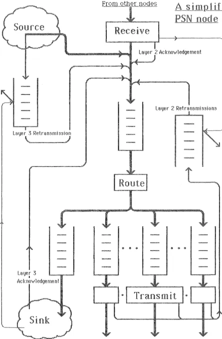
A PSN can be viewed as a collection of nodes connected by
lines (see figure 2). Each node consists of:
- a source of packets. This generates packets and handles layer 3 retransmissions
- a sink. This accepts packets which are at their destination and handles layer 3 acknowledgements
- a receiver. This receives packets and generates layer 2
acknowledgements
- a route procedure that sends a packet to the sink or an
output line depending on its destination
- a transmit procedure which sends a packet to another node
and sets up a layer 2 retransmission. This procedure also introduces transmisson errors.
2.2 Simulation Program
The model consist of three main classes; a link class
"Packet", and two process classes "ServerClass" and "NodeClass".
The link class Packet acts as the packets of the network and is
passed between the instances of "NodeClass". Each instance of
"NodeClass" represents a node of the network. There is one
instance of the "ServerClass" which represents the lines of the
network. It's procedures "Acquire" and "Release" ensure mutual
exclusion on the lines of the network. As well as these classes
to model the operation of the network the class "StatsCollecter"
contains all the statistic gathering and reporting procedures
used by the program. The procedure "Initialise" as its name
suggests intialises the network by reading from the configuration
file. The process class RunningMessage displays a message on the
terminal every 5 simulated seconds indicating that the model is
still running and how many simulated seconds have elapsed.
The logical structure of a node of the model is displayed in
figure 3 and a more detailed description of the function of each
procedure makes up the remainder of this section.
2.2.1 ServerClass
This process class ensures mutual exclusion on the lines
between the nodes. The boolean array "channelfree" indicates the
Figure
2
Rec iv
Layer 2 Acknov1ledgement
La
tJe r
2 Retrans
missionsLayer 3
u
Ack no,\,1 edge rne nt
• Transtni
t
@"Acquire" and "Release".
The procedure Acquire places the current process into a
queue for the required line and then waits until that line is
free. Once it is free the start of the use of that line is
monitored then the array "channelfree" is altered to indicate
that the line is no longer free. Finally the current process is
removed from the waiting queue.
The procedure Release monitiors the end of the use of the
line and changes the state of the line to free. It then wakes up
the first process waiting for that line if there are any.
2.2.2 NodeClass
This class and its related process classes (described in
section 2.2.3) model the activities that take place within each
node of the network. The procedure "L2Receive" handles the
reception of packets from other nodes in the network. The
procedure "Route" is called by "L2Receive" or "EmptyL3waiting" to
decide where the packet should next be sent unless the packet is
an acknowledgement in which case the procedure "Acknowledged" is
ca 11 ed by "L2Recei ve" to process the acknowledgement ( an RR
frame).
The procedure "Route" activates the Sink process if the
packet has reached its destination otherwise the "Outputline"
process for the next line on the packets path is activated. This
process calls the procedure "Transmit" to schedule the
retransmission and carry out the actual mechanics of the
transmission.
The procedure L2Receive is responsible for receiving packets transmited from other nodes of the network. It ensures that there
is a spare buffer available for the arriving packet, that there
have been no transmission errors and the packet is in sequence at
layer 2 before the packet is accepted for further processing.
There are four possible ways in which an incoming packet can be
processed. If the packet has been correctly received and is an
information packet the local layer 2 receive state variable
"L2VR" is incremented and the layer 2 acknowledgement timer is
restarted. If the layer 2 receive window has been reached a layer
2 acknowledgement (an RR frame) is created and added to the head
of the input queue and the receive window is advanced. Finally
the information packet is added to the end of the input queue and
the procedure "Route" is called. If the received packet is a
layer 2 acknowledgement the procedure "Acknowledged" is called to
process the acknowledgement and the packet is not added to the
input queue and route is not called. If the packet is a layer 3
acknowledgement that has arrived at its destination then the
procedure "Acknowledged" is called to process the acknowledgement
and the packet is not forwarded. Otherwise it is added to the
The procedure L3Receive is called by the process class
"Submitter" (see section 2.2.3.4) to introduce packets to the
network via the queue "L3waiting" once the source has created the packets.
The procedure EmptyL3waiting is called by "L3Receive" or
"Acknowledged" to take packets from the queue "L3waiting", set up
a layer 3 retransmission, add the packet to the input queue and
call the procedure "Route". This procedure also increments the
layer 3 send state variable "L3VS" each time it adds a packet to
the input queue and will not add a packet to the input queue if
the layer 3 send window has been reached for that packets
destination.
The procedure Acknowledged is called when a layer 2 or 3
acknowledgement has been received, it then searches the
appropirate queue ("L2unacknowledged" or "L3unacknowledged") for
all the pending retransmissions that are acknowledged by the
received packet. The send window of the correct layer is then
advanced if any retransmissions were acknowledged and the buffers occupied by the pending retransmissions are freed.
The procedure Route takes the first packet from the input
queue and determines if it has reached its destination; if so it
is added to the DTE queue and the sink is activated. If not the
procedure "FindLine" is called to determine the "Outputline" the
packet should be transmitted on. The packet is then placed in
either, the priority output queue if it is an acknowledgement or
in the output queue, and then the output process for that line is activated.
The procedure FindLine is local to the procedure "Route" and called to determine which of the available output lines should be
used for this packet. The way in which this line is selected
depends on the routing method being used by the network. If
static routing is being used the line is selected by a simple
table look up. If one of the biased shortest queue methods is
used the selection amongst the possible options is made by
comparing the lengths of the priority and normal output queue
lengths of each line.
The procedure Transmit handles the mechanics of the actual
transmission and is called by the output process to actually
transmit the packet. This procedure sets up a layer 2
retransmission, determines if a transmission error has occured,
acquires the line, holds for the time required to transmit the
packet, releases the line, and finally calls "L2Receive" of the
destination node to pass the packet on.
The procedure Debug is called by "L2Receive" and "Transmit"
if the global flag "debugon" is true indicating that debugging
output is required. It prints the debugging output for the
packet received or sent to the debug file.
Conceptually these processes are part of the node and should therefore be declared within the class "NodeClass" however
in Simula process classes must be declared at the outer most
level •1 This will explain the sometimes convoluted use made of the
S imula\dot notation.
' ~ 4,._
s·1Mv1.,w-r10/J2.2.3.1 TimerProcess
This process creates a layer 2 or 3 acknowledgement,
advances the appropriate receive window, adds the acknowledgement
to the head of the input queue, and calls "Route" to send the
acknowledgement on its way. This process is reactivated each
time a packet is received at the corresponding layer so that it
will only become active if the gap between two incoming packets
at either layer 2 or 3 is larger than the delay of the
reactivate. That is if the gap between the packets is larger than the acknowledgement timer.
2.2.3.2 OutputProcess
This process takes packets from either the priority output
queue if it is not empty or the output queue, and calls the
procedure "Transmit" to transmit the packet to the node to which
this output line is linked. At the same time the layer 2 send
state variable "L2VS" is incremented. This process continues
sending packets until the layer 2 send window is reached or both
output queues are empty.
The procedure PriorityPackets takes packets out of the
priority output queue and transmits them to the node to which
this output line is linked. Note that packets in this queue are
sent in preference to packets in the output queue.
2.2.3.3 Source
This process creates the packets that are to be passed
around the network. As the packets are created they are placed in
the source queue and the process "Submitter" is activated to
submit the packet to the network. The distributions used in the
source are discussed in section 3.1 and a means of experimenting
with the source parameters is discussed in section 5 of this
report.
2.2.3.4 Submitter
This process is activated by a "Source" and calls
"L3Receive" so long as there is a buffer available and the source
queue is not empty. If there is not a buffer available the
process holds for a short time and then continues attempting to
submit packets.
2.2.3.5 Sink
them after first checking if they are acknowledgements or
information packets. If the packet is a layer 3 acknowledgement
(no other acknowledgements reach the sink) the procedure
"Acknowledged" is called to cancel the pending layer 3
retransmissions that the acknowledgement covers. If the packet
is an information packet and is in sequence at layer 3 the fact
that the packet has arrived is recorded by the monitor, the layer
3 receive state variable is incremented, and a layer 3
acknowledgement is created if the layer 3 receive window is
reached. If the packet is out of sequence it is discarded.
2.2.3.6 Retransmitter
This process is activated by the procedure "Transmit" or
"EmptyL3waiting". It holds for a specified time and then adds
the packet it was set up with to the head of the input queue and
calls "Route" to send it on its way. It will continue to do this
until the boolean needed is set to false. This is done in the
procedure "Acknowledged" when the approiate acknowledgement has
been received. Each instance of this process class is placed in
either the "L2unacknowledged" or "L3unacknowledged" queue
depending on which layer the retransmission is set up by.
2.2.4 StatsCollecter
There is one instance of this class; "monitor". As it name
suggests this class contains all the statistic gathering and
reporting procedures.
2.2.4.1 The collection procedures
These procedures collect the statistics produced by the
model. The procedures "UtilStart" and "UtilEnd" monitor the
utilisation of lines. The procedure "Acknowledgements" monitors
the number of times the procedure "Acknowledged" is called, that
is how many layer 2 or 3 acknowledgements are received. The
procedure "Waiting" monitors the time a packet spends waiting for a line. The procedure "Creation" monitors the creation of packets
at each source. The procedures "Entry" and "Departure" measure
the amount of time a packet sends in each node. The procedure
"PacketTransfer" notes the successful arrival of a packet at its
destination and collects information from the packet on the time
it spent in each node. The procedure "Error" counts the number of packets with transmisson errors that are transmitted between each
pair of nodes. The procedure "BufferUtilisation" monitors the
utilisation of buffers in each node. The procedure "Bufferlack"
notes the number of occasions on which a packet can not be
received because there is no free buffer in the node. For a
detailed description of the statistics gathered by these
procedures see section 3.3.
The procedure "Reset" initialises all the statistic
collecting variables and is called twice, in the main program.
Once before the start of the presimulation period and again
2.2.4.2 The procedure Report
This procedure calls the eleven reporting procedures to
print out the gathered statistics in suitable formats. The report
is written to the file outf. The external name of this file is
specified by the user when the program is run. A message is
displayed on the screen as soon as this procedure is called to
indicate that the simulation is complete and that the report is
being writ ten.
The procedure Mean is called by several of the reporting
procedures to calculate the mean of the passed values. Note that
this procedure returns zero instead of attempting to divide by
zero.
The procedure StDev is called by several of the reporting
procedures to calculate the standard deviation of the passed
values. Note that this procedure returns zero instead of
attempting to divide by zero or find the square root of a
negative number.
2.2.5 Initialise
This procedure constants and calls
each node and to
related processes.
reads from the configuration file the network "EstablishNode" to read the data required for
create an instance of "NodeClass" and its
The procedure EstablishNode is called to read each node
description from the configuration file and to create an instance of "NodeClass" and one instant of each of its related processes.
2.2.6 Main Program
The main program calls the procedure "Initialise" to
establish the network, it then activates each source and the
"RunningMessage" process. The "monitor" is reset, the program
holds for the presimulation time, the "monitor" is reset again,
and the program holds for the simulation time. Finally the
"monitor" reports the statistics and all open files are closed.
3 Use of the model
3.1 The configuration file
The configuration file describes the network to be modelled. It consists of a network title (not more than 80 characters), the
number of nodes, and the routing method followed by a number of
node descriptions and finally some network constants.
Each node description consists of the name of the node
more than 6 characters), the number of buffers in the node,
number of output lines from that node, a number of
descriptions, a description of the source associated with
node, and finally an initial routing table.
For static routing this table consists of a pair of node
numbers, the desired destination and the packets immediate
destination. For the biased shortest queue methods instead of one
immediate destination up to five alternatives may be specified
(if less than five are required the rest must be 0). Each line
description consists of the destination of the line, its
transmission rate (in bits per second), its length (in
kilometres), its propagation time (in microseconds per
kilometre), and the bit error probability for the line.
The description of the source gives the average intermessage
time, the average interpacket time, the mean length of each
message in packets, and the resubmission back off time. The
source generates messages consisting of one or more packets with
a negative exponential delay between the completion of one
message and the start of the next, the mean of this delay is the
intermessage time. There is a negative exponential delay between
the packets that make up a message, the mean of this delay is the
interpacket time. The number of packets in each message is
negative exponentially distributed. The destination of each
message is uniformly selected from all the nodes in the network.
This source was designed to give an interesting packet
creation pattern based on what seem to be reasonable assumptions.
No claim as to the representative nature of this source is made.
The limited amount of published data on traffic generation for
Packet Switched Networks makes statisical analysis leading to the
formulation of a general source impractical. To assist in the
selection of source parameters a small program called the source
emulator has been written and is described in section 5 of this
report.
Note that words in a configuration file, except the
and node names, are ignored by the program; they are
make the file more readable for the user. The relative
of the numbers are important so the blank lines and
containing words must be retained to ensure the
interpretation of the numbers by the program.
network there to post ions the lines correct
3.1.1 Routing algorithms
There are at present three routing methods [3,10] available:
1. Static Routing - this entails a simple table
look up from a static routing table
2. Biased Shortest queue (ignoring line speed)
- this entails selection of the
output line from a range based on queue length for each line
3. Biased Shortest queue
- this entails selection of the
output line from a range
An exa~Ele configuration file
based on queue length for each line and the speed of that line
Figure 4 shows the configuration of this network, all the
lines are run at 64 kilobits per second.
Configuration Example
4 nodes
2 Biased shortest Queue (ignoring line speed)
Node 1 CHCH
50 buffers 3 output lines line dest, speed,
2 65536
3 65536
4 65536
length (km) , 390 1065 360
propagation, 4
4 4
error prob. 0.00005 0.00005 0.00005
source (intermessage, interpacket times; packets/message; backoff) 1.5 0.2 1.25 0.015
routing table (to, via) l 1 0 0 0 0
2 2 3 4 0 0 3 3 4 2 0 0 4 4 2 3 0 0
Node 2
WELL
50 buffers 3 output lines
line dest, speed, length (km), propagation, error prob.
1 65536 390 4 0.00005
3 65536 675 4 0.00005
4 65536 750 4 0.00005
source (intermessage, interpacket times; packets/message; backoff) 1.5 0.2 1.25 0.015
routing table (to, via) 1 1 3 4 0 0
2 2 0 0 0 0 3 3 4 1 0 0 4 4 1 2 0 0
Node 3 AUCK
50 buffers 3 output lines
line dest, speed, length (km), propagation, error prob.
1 65536 1065 4 0.00005
2 65536 675 4 0.00005
4 65536 1425 4 0.00005
routing table (to, via) 1 1 2 4 0 0
2 2 4 1 0 0 3 3 0 0 0 0 4 4 1 2 0 0
Node 4 DUND
50 buffers 3 output lines
line dest, speed, length (km), propagation, error prob.
l 65536 360 4 0.00005
2 65536 750 4 0.00005
3 65536 1425 4 0.00005
source (intermessage, interpacket times; packets/message; backoff) 1.5 0.2 1.25 0.015
routing table (to, via) 1 1 2 3 0 0
2 2 3 1 0 0 3 3 1 2 0 0 4 4 0 0 0 0
routing alg time 0.0001
frame check seq time 0.0
time to process an acknowledgement 0.00001 0.005
Send window size 7 3
Receive window size 7 2
retransmission timer (in bit times) 28000 70000
Acknowledgement timer (in bit times) 4000 4000
3.2 Simulation times and seeds
The presimulation time allows time for a number of packets
to be sent through the network before the statistics collection
commences. This means that there may be several packets in
transit when the actual simulation commences and thus i t is
possible for a few more packes to arrive than were generated
during the simulation time. This also means that some of the
buffers and lines of the network will be in use at the time the
actual simulation occurs. A presimulation of less than 20 seconds
will be adaquate in most cases as a longer time than this will
simply allow large numbers of packets to pass through without
being measured.
The simulation time should be of a reasonable length. It
should not be less than 120 seconds for realistic simulation
because of the small number of packets that are generated and the
performance. The model when run on a Data General Eclipse S/130 takes approximately 2.5 minutes of actual time for each minute of
the simulation. However the Eclipse used did not have a floating
point unit and so real numbers have to be simulated by software
reducing the running speed of programs.
The five random number seeds should be odd and have no
obvious pattern. They are included in the statistics report so
that they may be used again to repeat an experiment under the
same workload patterns but with different network configuration.
The first seed is used to determine if a transmission error has
occured, the second determines the intermessage gap, the third
determines the number of packets in a message, the fourth
determines the destination of a message, and the fifth determines the interpacket gap.
3.3 The collected statistics
3.3.l Title
The title gives the network name, the presimuation time,
simulation time, and random number seeds. This information allows
the user to recreate an experiment using different network
configurations to examine the effects of various changes.
3.3.2 Number of packets created
This table gives the number of information packets created
at each node destined for each other node during the simulation
time.
vJ.3.3 Packet transfer times
This table gives the number of information packets
sucessfully transmitted between each pair of nodes in the
network, the minimum, maximum, and mean times taken and the
standard deviation of these times. The maximum may be several
times the minimum if any retransmissions have occured. Note that
if the presimulation time is non-zero there may be slightly more
packets transmitted than created as some packets created during
the presimulation time may still be in transit. This table gives
an indication of the overall network performance.
/ 3. 3. 4 Time spent in each node
This table gives an indication as to where in the network
information packets are spending their time. The time spent in a
node is the time between the arrival of the last bit of the
packet at the node and the sucessful departure of the last bit of
the packet from the node-.-Ifi:he-packet suffers a transmission
error it is not considered to have succesfully departed the node.
The distinction between local and nonlocal is made to stop the
very short times spent in the destination node artifically
lowering the mean time spent in a node. A packet is in a local
therefore simply handed to the DCE.
3.3.5 Number of packets with errors received
This table gives the number of packets suffering
transmission errors transmitted between each pair of nodes. This
does not include errors suffered by acknowledgement packets.
3.3.6 Number of Retransmissions
This table gives the number of information packets that have
been retransmittred between each pair of nodes at layer 2 and
layer 3. This table gives a good indication as to how well the
network is recovering from errors that do occur. If large numbers
of retransmissions occur while there are little or no errors it
is an indication that either the retransmission timer is too
short or that the acknowledgement timer is too long.
3.3.7 Number of acknowledgements
This table gives the number of acknowledgement frames (at
layer 2) and packets (at layer 3) that have been successfully
transmitted between each pair of nodes. If the number of
acknowledgements is excessive this is an indication that the
acknowledgement timer is too short or that the receive window is
too small.
3.3.8 Line Utilisation
This table gives the percentage utilisation of each line in
the network. If any of these utilisations are excessively high
this will be reflected in high wait times for lines and high
times spent in the affected nodes.
3.3.9 Wait times for lines
This table gives
waiting for the lines of transmission once it has and stops when its first
3.3.10 Buffer Utilisation
the time that information packets spend
the network. A packet starts waiting for
been routed to a particular output line
bit is transmitted.
This table gives the percentage utilisation of buffers in
each node by both information and acknowledgement packets. A
buffer is used by a~ information packet from the time it is
received until an acknowledgement for it arrives. At the source
of the packet the acknowledgement must be at layer 3, at
intermediate nodes on its path a layer 2 acknowledgement frees
the buffer. The buffer of an acknowledgement packet is freed as
soon as its contents has been transmitted.
3.3.11 Packets rejected due to lack of buffers
accepted by a node because there was no spare buffer in the node.
If the packet was submitted by the source of the node this is
considered a local rejection. If the packet should have been
received from another node this is considered a nonlocal
rejection. These should be zero, if not the configuration has
major problems in transmitting the offered workload.
3.4 The Dump and Debug files
The Dump and Debug files are provided to assist in the
modification and validation of the model. The dump files provide
a means of ensuring that packets are indeed arriving at their
destination in sequence and without duplicates. One dump file is
produced for each node in the network and is numbered with the
number of the node that produced it (for example dumpl is the
dump file for node 1). A dump file has the following form:
Packets receive by Node 1. From Nodes:
1 2
1
2 3
1
2
This indicates that node 1 has received packets 1,2 and 3 from
node 1 and packets land 2 from node 2. Note that the packets are indeed in order and there are no duplicates.
The debug file shows the packets that are transmited between
a given pair of nodes and the values of various state variables
in each node. Figure 5 attempts to clarify the format of the
debug file output, it should be read in conjunction with the
following example debug file. It should also be noted that layer
2 retransmissions are indicated by an"*" to the right of the NS
and layer 3 retransmissions by a
"+"
(neither occur in thisexample) .
4 An example of use
The following is a simple example of the use of a model on a
network. The configuration file, the terminal session, and the
output from the model are presented.
An example of~ configuration file
This configuration file is called NZPO.
NZPO Packet Switching Network
3 nodes
1 Static routing
RR(l)
-)
R.R (1)
I(l,1)
Error!!!
LL
Note: The two errors
and the out of sequence packet occure<:l on another line.
Note: this out of sequence
packet oc<;urs
on
another
line.
Note: this error occw·rs on another line.
:i. DEBU(3
""' ,_,. ,..~ ,,_. W•-•
CHCH l-JEI....L..
L:?'-.Jf; 1..:::::,.; 1:~ bc~nc:I L./;\Ji3 L..:.s,..J I~ bE')l"lCI hiU l"il..\1Y1i:JG) r l\lf< L. .. 2\JU L.2\/F~ b0,)'rK1 l.. .. '..'5\)E\ L ... :S'v' F{ t'.)i:,:.:,~·nc:I
ht:i. 'r''1ci O VJ tAJ :L \'"tel Ci v·J ltJ :i. nu C) 1/·.J l;\l :i. )•'ic:i 01/1)
'.:5C:!l"iCi :i. 0 7 :I. 0 ··; ( I :l 0 :i. ::;~ i
i :I. 0 :l •'"1
I 0
,,::. .I. 7 0 () '"?' l''(:':)C:·<-:-? i. \/E:
I :I. F< H :I. •"'1
.,::. i 0 :i. 7 0 l 7 i,'i<·,;·nd
l"E-)Cf:,' :i. V<·::.> 1 0 0 :i. 0 7 I :I. F~ Fx :I. ::;:: I
:I. L .. ~.~ f~ I:( :I. ~;:: i 0 ·I
7 (; :I. 'fl :;;1ar·,d
.I.
\''E:!CE,! i. VE' :I. 0 0 :i. 0 0 I :i. L .. i''; F~ F< :i. ::;;: I i:::: l'' l"O \'' !
:
!Ciut 0 f E,c:1q
E r rel \' !
:
!:I. 0 :I. :? i :i. I. 7 :I. :I. 7 1':i(0)Y'1C/
l"E!CE) :i. \vJ(,:,:, :i. :l 0 :l. () () I J. 0 :1. ::;:: I
'.',E':!'r'iCI J. l 0 :I. :J. () I :i. Fl f< 1. ::? I
:l F<H :l :? i :I. :I. 0 :I. :I. 7 l''E!Cr? :i. V0:!
1',E·:inc:I l. :i. 0 :L :L () I :i. 1...::::, F<H :i. ::;:: I
Ciut 0 f: Hr:.~o
:I. L::i: F1 F< l :;? i :I. :I. 0 :i. :i. 0 l''E'·'("'• f" :i. \/(·)
\,5E!l"lci :;;:: 1 0 :~'.: :i. 0 I :i. 1 ,'·'i
.,::. :;;:: I
:i. :I. ,'"1
.,::. ~? i :I. :? 0 :L :I. 0 l"C,!C(·:'.! :i. \/0:)
:i. F~ F< :? :;;:: I :1. :;? ( ) :I. :? 0 SE,'\·"10
rc-~~C:'E·) :i. \If~ :? :I. :i. :~::: :I. (' .) I :I. I~ F~ ::~: ::? I
i :I. !...:,; F<
i<
•'"1,,::, ::? i 1. :? 0 :I. :? 0 r,;£,inc:i
rt,iCC') :i. Vt,) :? :I. :i. ... .,'.:. :I. :i. I :I. I .... ::::; 1:{H :? ::;:: I
I:::. '(' l'' C) \'' ! ! !
1::i(i!l"id :·:5 :i. :L ";!'
\.,I ). l I :1. ::? ::.:; ::;~ j
I :I. :? ::!; ::? i :I. ":i·
0 :i. , ... , 0 l''l2Ci::! :i. Vf0
\-"' .,::.
ic;r,inc:i l~J. :1. :i. t.1. :I. :i. i :L ·:!'
\.,} 1:1. ::;:: I I:::. r r· ci r ! ! !
:J. f~ F~ .. 1,,, :;· :? i :I. l/. () :I. ll, 0 13(·::.'\"\d
\"t·'!Ct::) :i. Vf::! Ii. :i. :.::; l'.1. l 1 i :I. F< F~ ··:~· ....
50 buffers 2 output lines
line dest, speed, length (km), propagation, error prob.
2 65536 390 4 0.00005
3 65536 1065 4 0.00005
source (intermessage, interpacket times; packets/message; backoff) 1.5 0.2 1.25 0.015
routing table (to, via) 1 1
2 2 3 3
Node 2 WELL
50 buffers 2 output lines
line dest, speed, length (km), propagation, error prob.
1 65536 390 4 0.00005
3 65536 675 4 0.00005
source (intermessage, interpacket times; packets/message; backoff) 1.5 0.2 1.25 0.015
routing table (to, via) 1 1
2 2 3 3
Node 3
AUCK
50 buffers 2 output lines
line dest, speed, length (km), propagation, error prob.
1 65536 1065 4 0.00005
2 65536 675 4 0.00005
source (intermessage, interpacket times; packets/message; backoff) 1.5 0.2 1.25 0.015
routing table (to, via) 1 1
2 2 3 3
routing alg time 0.0001
frame check seq time
o.o
time to process an acknowledgement 0.00001 0.005
Send window size 7 7
Receive window size 7 7
retransmission timer (in bit times) 28000 70000
Figure 6 shows the configuration of this network, all lines are run at 64 kilobits per second.
An example screen dialouge
psn
Enter name of configuration file >nzpo
Enter name of the statistics file >report
Enter y for dumps >y
{enter nothin9 if dumps not requiredJ
Enter y for debugging >y
Enter numbers of left and right nodes >l
>2
Enter 5 random number seeds >12345
>22345 >32345 > 42345 >52345
{asked only if answered y to debugging question}
{bad random number seeds because of pattern}
Enter Presimulation and Simulation time (in seconds)
>5 {both times are too short}
>60
Running! Running! Running! Running! Running! Running! Running! Running! Running! Running! Running! Running! Simulation
5 seconds elapsed 10 seconds elapsed 15 seconds elapsed 20 seconds elapsed 25 seconds elapsed 30 seconds elapsed 35 seconds elapsed 40 seconds elapsed 45 seconds elapsed 50 seconds elapsed 55 seconds elapsed 60 seconds elapsed
complete, writing report.
This run of the model will produce the files; report, dumpl,
durnp2, and debug. In most cases only the statistics report will
be required.
An example report
This output is in the file report.
Report on the
---NZPO Packet Switching Network
Presimulation Time, Simulation Time (seconds)
5.00 60.00
Wellingt~~
Christ.church
Etgure
6
The New Zealand Post Office
12345 22345 32345 42345 52345
Number of packets created
---Source Destination
CHCH WELL AUCK Total {note variation in the
CHCH 14 26 11 51 number of packets
WELL 19 13 11 43 between each pair of
AUCK 13 19 11 43 nodes due to the short
'l'otal 46 58 33 137 simulation time}
Packet transfer times (milliseconds)
---~~---~---From To Number Mean StDev Minimum Maximum
CHCH CHCH 14 0.04854 0.05191 0.00124 0.11501
CHCH WELL 2 75.17070 162.98880 17.91768 637.61499
CHCH AUCK 11 21.34470 1. 93610 20.61766 27.17564
WELL CHCH 19 18.02789 0.10054 17.91768 18.13098
WELL WELL 13 0.05842 0.05247 0.00016 0.11231
WELL AUCK 11 135.69739 199.49614 19.05920 446.31519
AUCK CHCH 13 20.7619Q 0.09664 20.61835 20.83246
AUCK WELL 19 41.88597 98.95015 19.05740 450.49927
AUCK AUCK 11 0.06987 0.05143 0.00017 0.11429
Total 137
Time spent in each node (milliseconds)
----~----~~~~~--~---~
Node CHCH WELL AUCK Node CHCH WELL AUCK Number From CHCH CHCH CHCH WELL WELL WELL AUCK AUCK AUCK Total LocalNumber Mean StDev
46 0.06014 0.05062
64 0.05397 0.05094
37 0.05854 0.05148
Nonlocal
Number Mean StDev
37 40.39417 138.34636
30 42.78459 130.34767
32 13.55060 76.25642
of packets with errors received
At CHCH WELL AUCK CHCH WELL AUCK CHCH WELL AUCK Number 0 3 0 0 0 1 0 1 0 5
Number of Retransmissions
From Layer 2 Layer 3
Minimum Maximum
0.00005 0.11501
0.00000 0.11519
0.00017 0.11513
Minimum Maximum
0.00024 619.69751
0.00026 427.25757
CHCH WELL AUCK Total Number 6 3 1 10 of 0 0 0 0 acknowledgements
---From To Layer 2 Layer 3
CHCH CHCH 0 13
CHCH WELL 15 15
CHCH AUCK 12 12
WELL CHCH 20 20
WELL WELL 0 12
WELL AUCK 17 17
AUCK CHCH 8 8
AUCK WELL 10 10
AUCK AUCK 0 8
Total 82 115
Line Utilisation
____________
.._ ... .,,,...,...._From To Utilisation ( % )
CHCH WELL 1. 04101
CHCH AUCK 0.61235
WELL CHCH 0.72072
WELL AUCK 0.63982
AUCK CHCH 0.58011
AUCK WELL 0.75008
Wait times for lines (milliseconds)
From To Number
CHCH WELL 31
CHCH AUCK 12
WELL CHCH 19
WELL AUCK 14
AUCK CHCH 13
AUCK WELL 20
Buffer Utilisation
Node CHCH WELL AUCK
Utilisation (%)
2.31098 2.17135 2.16057 Mean 20.36418 0.54976 0.00642 0.00682 0.00654 0.21535 Minimum 0.00000 0.00000 0.00000 StDev 111. 24162 1.89218 0.00528 0.00455 0.00492 0.93697 Maximum 4.00000 4.00000 4.00000
Packets rejected due to lack of buffers
Node CHCH WELL AUCK Local 0 0 0 Nonlocal 0 0 0 Maximum 619.69751 6.55823 0.01424 0.01440 0.01331 4.19605 Available 50 50 50
The following are some of the observations that can be made
together with the high number of acknowledgements indicate that there are large gaps between packets and therefore the network as
configured is capable of tramsmitting a lot more traffic. If the
traffic offered to the network is as described the network could
most probably could be run using 9600 bps lines. This could be
confirmed by another run of the model. The large number of
retransmissions relative to the number of errors indicates that
the retransmission timer may be too short. The high number of
acknowledgements may be reduced by increasing the acknowledge
timer, this must however remain less than the retransmission
timer. Further runs of the model could also be made with higher
and higher workloads to give an indication of how the network
will react to increased load.
An example of a dump file: dumpl
These files are produced only if you responded "y" to the
prompt "Enter y for dumps".
Packets received by Node 1. From Nodes:
1 2 3
---·---12
3 4 5 6 l
1 7
2
8
9
1 {note end of presimulation period}
1
2
3 4 1
2
3 5
2
{ and so on}
An exam:e_;te of the debug file
This file is produced only if you responded "y" to the
"Enter y for debugging", it is 130 characters wide. See the
following page for an example and section 3.4 for an explanation
send
recei ve
recei ve
rece i ve send
send
send
send
rece i ve
rece i ve
send
send
rece i ve
rece i ve
seno
rece i ve
rece i ve
send
send
rere i ve
rece i ve
rer~ i ve
send
send
{ and s 0 a n
CHCH
L2V8 L2VR Send L3VS L3VR
wi nci aw
1 0 7 1 0
l 0 0 1 0
1 0 0 1 0
1 1 0 1 0
1 1 0 1 1
1 1 0 1 1
2 l 0 2 1
~ 1 2 2 1
2 l l 2 1
2 1 1 2 1
3 1 1 3 1
4 1 1 4 1
4 l ·:r w 4 1
4 l 3 4 1
~
J 1 3 5 1
5 1 4 ~
J 1
~
1 4
=
10 0
6 1 4 6 1
6 1 6 6 1
6 1 ~
7 1
0
6 1 ~
0 7 1
6 2 ~
0 7 1
6 2 5 7 ~
L
6 ~ ~
7 2
0
5 The Source emulator
The source emulator is designed to assist in the selection
of the three main parameters of a source: intermessage time,
interpacket time, and the average number of packets in each
message. Given the three parameters and a simulation time it
produces a histogram of the number of packets generated against
time and the average number of packets generated per second and
per hour during the simulation period. The fourth parameter for a
source in the configuration file is the time that the source
waits before attempting to resubmit a packet that has been
rejected by a node because there was no free buffer for it. This
can not be simulated by the source emulator as there is no way of
simulating buffer congestion except by running the main model
which does not collect these detailed statistics on packet
creation. This timer is not used unless packets are rejected due
to a lack of buffers.
An example run of source emulator:
Ineut:
enter name of outputfile (nothing for screen)
>
enter width of histogram classes >5
enter 3 random number seeds >12345
>22345 >32345
enter intermessage and interpacket times >1.5
>0.2
enter average number of packets per message >1.25
enter simulation time >30
Output:
Random number seeds
12345 22345 32345
Intermessage and Interpacket time
1.50000 0.20000
Average number of packets per message 1.25
Time
I****
5.00
******
10.00
*********
15.001
*******
20.00
******
25.00
*****
30.001
4
6
9
7
6
5
Average number of packets generated per second 1.23
Average number of packets generated per hour 4440.00
The program has three procedures Initialise, Report and
Plot, and one Process Class Source. The procedure Initialise
asks the user for an output file name, the width of the histogram
classes, 3 random number seeds, the three source parameters, and
the simulation time. If there are more than 60 classes in the
simulation time it is shortened and the user is informed. The
prodecure Report as its name suggests writes the report for the
program, it calls the procedure Plot to plot the histogram. The
process class Source is the same as that in the model except that
instead of introducing packets to the network it calls the
standard procedure histo to update the histogram.
6 Conclusion
This model appears to succesfully model the behaviour of a
packet switching network with similar internal protocols to that
described in section 2.1 of this report. The limited amount of
testing carried out supports this assertion in comparison with
the New Zealand Post Office Packet Switching Network. It should
be noted that the Post Office network implements piggybacking.
The model however requires validation, one possible means of
doing this would be to compare the results obtain from the model
with those of an actual network. There is extensive room for
further work on this project particularly in providing a better
workload description and source of packets. Further work could
also be undertaken in allowing the user to specify some aspects
of the internal protocol to enable the model to be applied to a
wider range of networks. The inclusion of further routing
algorithms is another area with large scope. Finally the actual
use of the model to predict the performance of an actual network
or to assist in the design of a real network should be the
ultimate aim.
7 Acknowledgements
Acknowledgement is made of the assistance rendered by the
New Zealand Post Office on some of the more technical questions
that where raised during the course of this project. The
8 References
1. CCITT Recommendation X.25, Fascicle VIII.2
Data Communication Networks - Yellow Book, Geneva, July 1981.
2. CCITT Recommendiation X.200 COMM VII R22(C)-E,
Geneva, 1981.
3. "Network Protocols",
Andrews. Tannenbaum,
Computing Surveys, Vol. 13, No. 4, December 1981.
4. Proceedings of the IEEE, Vol. 71, No. 12,
December 1983.
5. Sloman M.
s.,
"X.25 explained", ComputerCommunication, Vol. 1, No. 6, December 1978.
6. Pouzin L., "Methods, Tools, and Observations
on Flow Control in Packet-Switched Data Networks", IEEE Transactions on Communication, Vol. COM-29, No. 4, April 1981.
7. Boorstyn R. R. and Livne A.,
"A Technique for Adaptive Routing in Networks", IEEE Transactions on Communication, Vol. COM-29, No. 4, April 1981.
8. Chou
w.,
Bragg A.w.,
and Nilsson A. A.,"The Need for Adaptive Routing in the Chaotic and Unbalanced Traffic Environment",
IEEE Transactions on Communication, Vol. COM-29, No. 4, April 1981.
9. Alton B., Patel A., Purser M., and Sheehan J.,
"The Performance of a Packet Switched Network -A Study of EURONET", Proceedings of the
International Conference on Performance of Data Communication Systems and their Applications, Paris, September 1981.
10. Tannenbaum A.
s.,
"Computer Networks",.,.
Bl::13 I 1,1
SIMULATION BEGIN
comment**************************************************
·X·
Packet Switched Network Model
========================~====
*
Written by Paul Reynolds, ·)\·D c:\ t c:·:,1 2 0 I':'.! I :i. '::i B t.:1 ... ·i\· ************************************************** This model is designed to give information on packet
in X .. 25 Public Data Networks. It reads a description
network from the given configuration file and writes results to the given statistics file;
F<[F.
H1:::.1··
i··(i:::.I"' HEr::·
HEF
Hl:::1::·
Tl:::/T i"i':'1<':,\ 1 i''('.·'.•i·l 1
CNodeClass) array DSE <1=20)
(ServerClass) channel: (StatsCollecter) monitor;
( fl U 'r'l \·'l i. i"l(I JYi E?l'i> !:ii i':\<,;.i Ei) r U \·'\l"l :i. 'r''1 <,:J ;
(Ii\lFIL .. E) :i.nf;
COUTFILE) outf, debugfile;
(OLJTFILE) array dump(l:20);
networkname, dumpfile;
array acknowledgetimer<1=2> routingalgtime, FCStime,
p l'' f,,, \::; :i. 1Y1 t: :i. 1'(10~· ., ~; i 1Y1 t: :i. 1Y10:~ :;
:i. \Ti,; i-:1!(:!E! \'' i:':\ l"• r,Y~y S('}r?c:i ( :i. :: :~'i) ... :i. \·"1 :i. t '.'o(i:),'i7.•d ( :I. :: !j) 1
1.2vH < 1 ~
~::o.,
1 = 20) ., 1....:::::v1< < :1. = 20., 1 = :::::o) ., 1...::wr3 < :1. :: 20., :i. ~ 20) ., 1. .. ::.!;vi:~ < :t: 20., 1: 20) ., L2sendwindow<1=20, 1=20),L3sendwindow(J.i20, 1:20>, L2receivewindow(1:20, 1=20),
L3receivewindow(1:20, :i.=20);
int r'?g <''~ r 1Y1 i l"ll"i o d r,i ., 1Y1c:\ >-: r·i o c:I f:,1, i ., i' out :i nq,t,r:?t hon.,
L2timerc:ieiay, L3t:i.meraelay,
L2sendwindowsize, L2receivewindowsize, L3sendw:i.nciowsize, L3receivewinciowsize, L2windowtimer, L3windowt:imer,
1Y1 <':\ >-: !o, (·''.·) q u (~ n c 101 'r'l I..\ 1Y1 ...
J.0?ftnod0c'., ri(Jhtnoc:ic:!;
boolean dumpon, debuqon;
f} 0~\I
Of t hE~
COMMent: ********************************************************; LINK CLASS PacKet;
comment This class is passed around the network acting as
the packets in the network;
Dfa?Q :ln
boo1ean L2acknowledgement:, L3acknowledgement,
<01 r r o r, r(,:·it i''i,,\ ni::,1Y1 i
i,,i,,,
:i. on., l ic\yc:2 r:·.'.; ., c<'.1. J. l r1:::q uei::; t .,'r'iE''\; ~\JO i"·/·1;
integer source, destination, size, NS, NR, PS, PR;
real transtime, waitingtime; real array entrytime(11Ma>-:node),
tot i::\ l :i. rit f:? r·l'li:,\ l t :i.1¥10? ( :i. ~ t(li::\Hi"lOCif:::), :t I 2) ;
:i. n t r~ r;1 c-:-i r· 1··i u 1Y1 i::H11 r' :;
comment*****************************************************; CLASS BerverClass;
coMment 1nis js a collection of procedures relating to the
operation of the lines connecting the nodes of the \·')E·Jt v\l () r 1·1 ;
BE'(::J .i. tl
Hi:~.1-·: ( l···IE(.)D) c:\ r r,~1y v'Jc\ :i. t :l n(:;J ( :I. :: 1Y1E\ x no cl 0::• ., :I. :: 1Y1.:-:\ >-:no c:i (c~) ;
i:) o o l 0?c\ n t:1 r' r,e',\Y c: hii\ t1nE1 1 f rE!(i? ( :l :: 1Y1,,,\ ><no CJ F!, l :: 1Y1i,:\ >< ·r·1 o d (0:) ; :i. nt \,~q<:,·: r :i ... , J ;
C01Y11Y1E:nt M• .. -0<• ~, ... -h· ,-,,. ... ' " " " " ' ... ,,. ••••• ... <•<» ... ~. " ' . ' " " ' < A • • " ' " ' ~ - ° " " HO• ... O••,O ... " " ' .4 .. h< ... , " ' ' ' h<•O '"'" O,>o> ' ' " ' »~> ,.,,. ,,,,, , . , , . " ' " <•'" ,..,, ,.,_ 0,,., °"'' '''" ,,. .. '"'' "
Procedure Acquire(source, destination); integer source, destination;
.,
comment This procedure ensures mutual e><ciusion on each of the channels between the nodes. The queue 'waiting' contains those processes waiting for the channel to
be£·:C () 1Y1f!:: f' )"·(·:~£'! ;
B\':::<J :i. )··1
Cl../ I::< F~El\!T" I i\lTCJ ( i·\I,,,\ :i. t J. 1· .. 1q ( i;;; o u r··ct::i .,
While not channelfree(saurce,
pr:ii::;s I \lATE;
d c,: ~;; t :i. n c",\ t i on ) ) ;
d (·c: 1;;; t :i. 1··1 i',\ t i o )·1 ) cl o
1Y1 on i t o r'" u t i 1 ~-;; t <'\\ rt ( ~,, o u r' c (',·! ., c:i (:~ s::. t :i. n <",\ t i on ) ; chi"\ n·n1'? 1 f r'c·:·::[? < :;,, o u rc·(·::i, cl El:,,,t :i. n;:,\ t ion) i '"" ft'.\ 11::;f?;
CUPf<E!\iT .. UUT :;
End nf procedure Acquire;
comment-·----·---; Procedure Reiease (source, ciestination);
integer source, destination;
comment This procedure releases the channel and wakes up the first process waiting for tnat channel;
B<'i'i;J :i. n
H~~ (PROCESS) transmitter;
c h,:J l"ll"'1 (·,? 1 fr f,,l(·,? ( i:; o 1 .. t r'C<·:~ ., ci <':)\;;; t :i. n i::\ t i. on ) t ""' t r' u e ;
monitor.utilend(source, destination);
i f not waiting(source, ciestination),EMPTY then
b(':·!q:i.n
transmitter :- waiting(source, ciestination).FIRST;
t l'E~n:,:;1Y1 :i. t t f,: r . CJUT ;:
ACTIVATE transmittep; (:·:·))•'\cl :.:
End of procedure Release;
C C) 1Y1 1Y1 (!,' 'r''i t:
---·
comMent CLASS ServerClass initialisation;
f o r i. :: "" 1'11 i r·1 n o cl f:'i r:,; t F,' o :I. u ri t: i 1 1Y1 i::'1 >< 1·1 o ci E:· c:I o
for J
==
minnode step 1 until maxnode doiJc-,i<;,:_1 :i.n
w2~ :i. t i 1·"1g ( :i. ., J ) :: ... i\lti:t..J HEn:O ::
C h i:H'll''l (~ J. f' r E1 ('l ( :i. ., .J ) : "" t i'' I.H,! ;
€0l"H::I :;
End of CLASS ServerClass;
comment*****************************************************; CLASS NodeClass (node)
:i. nt c1q<-::1 r 1··1odf0;
comment This class is a collection of procedures dealing with the processes that take place within each node on the ni?ltwor'k, :.:
B<·?g :i.1··1
REF
l<f::: r-:~
Ht::.I"'
IH:::1::
(OutputPrccess) array outputline(1:maxnode) (Source) DTEsource;
\ G IJ I::) 1Y1 :i. t; t €-? l"• ) b U t:) 1Y1 i. 'I:; ;
( El :i. 'r'l Ii ) ).) I !:::. t,, l. n l·i ;
REF CTimerProcess) array L2timer(1:maxnode),
L3t:i.mer<i=maxnode); REF (HEAD) array outputQ(1:maxnode),
priorityoutputQ(1:maxnoda) REF <HEAD> inputQ, DTEQ, L2unacknowledged,
L3unacknowledgeci, sourceQ, L3waiting;
I I::)<; I 'r''1 o c:I f:·i n r:,\ 1Y1 t7! :;
:i. n t f·~ (;t f:i r ,,,, r' r' ,,,, '/ r· o 1J t :i. n q t ,,·,, i:l 1-f?.! ( :J. : 1Y1 ,,,, >< no c:I E) .1 :I. ,; ~':i ) ,
linechoice(1:maxnode);
integer buffersinuse1 totalbuffers;
comment---; Procedure L2Receive (massage, from>;
REF (packet) message;
:i. nt f'·iCJ €-,' r fro 1Y1 :;
coMment This procedure is called by the transmit procedure
of another node. This procedure adds the incoMming
message to the input queue of this node if there
is a spare buffer and there were no transmission
errors. The procedure Route is called to snift
Bt::GJ i 1··1
the message onto the correct outgoing queue. An L2acknowledgement is created and sent either by
the,i t:i.iiJ(';}l" prOCC-i!!;;,'i,i .. , :i.f thE~ Qi:iip bEitw0~(":'r1 th<·,:,· p<i,\Cl·~('::'G~;
is large or when the receive window size numoer o f ' I packets' have been received from that node;
REF (packet) ack, temp;
i f buffersinuse < totalbuffers then
b C·') (J :i. n
comment room for packet;
buffersinuse i = buffersinuse + l;
monitor.bufferutilisation(node, buffersinuse)
i f not (message.L2acknowleogement or
message.L3acknowledgement) then monitor.entry(message, node);
HCJI .... D < r:·c;r:;t :i. ,Y,E·: > :;
if message.error or (message.NS <> L2VR(from, node) and
not (message.L2acknowiedgement or
message.L3acknowlecigement)) then
bc,-?q:i.1··1
comment packets with errors or out of sequence are simply ciiscardea;
buffersinuse
=~
buffersinuse - 1;monitor.bufferutilisation(noae, buffersinusel