http://www.scirp.org/journal/wjet ISSN Online: 2331-4249
ISSN Print: 2331-4222
DOI: 10.4236/wjet.2017.54059 Nov. 16, 2017 707 World Journal of Engineering and Technology
Development of Jet Training FTD
(Flight Training Device) Overhead System
Daeil Jo, Yongjin Kwon
*Department of Industrial Engineering, College of Engineering, Ajou University, Suwon, South Korea
Abstract
Today, the growth of aerospace industry has led to the development of modular overhead systems that can be applied to a wide variety of aircraft. It actually maximizes training effectiveness by working in a similar way as to the real aircraft maneuverability. Overhead system control device for aircraft si-mulator is developed as a module and integrated to the flight sisi-mulator. The developed system can replace the similar products imported from overseas at a much lower price, about one third of the imports, while maintaining the same level of functionality and the performance with the counterparts. This price advantage is the main motivation of this development, which is expected to enlarge the commercial training simulator market in our country. This de-velopment has been also funded by the government, and we invited several commercial airline pilots to test the equipment. The post operation interview revealed that the developed system at least matches or exceeds the perfor-mance of the imported products. With the development completed, it is ready for the commercial production and will help promote the expansion of flight training education at various aerospace universities in Korea.
Keywords
Overhead System, Flight Simulator, Interface Board, FTD (Flight Training Device), Aircraft Panel
1. Introduction
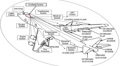
The FTD or flight simulator is a flight training device that provides the situation that is very similar to the real environment. In large commercial grade aircraft simulators, such as Boeing 747, the overhead system is one of the main instru-ment panels, which controls many critical functions. It consists of a function of engine start-up, electricity, hydraulic, fuel, environmental control, oxygen,
di-How to cite this paper: Jo, D. and Kwon, Y. (2017) Development of Jet Training FTD (Flight Training Device) Overhead System. World Journal of Engineering and Tech-nology, 5, 707-719.
https://doi.org/10.4236/wjet.2017.54059
Received: October 18, 2017 Accepted: November 13, 2017 Published: November 16, 2017
Copyright © 2017 by authors and Scientific Research Publishing Inc. This work is licensed under the Creative Commons Attribution International License (CC BY 4.0).
DOI: 10.4236/wjet.2017.54059 708 World Journal of Engineering and Technology
small demand in flight simulator market in Korea, the overhead system panel has been imported from foreign countries and installed on the flight simulators that have been domestically manufactured and sold to various flight training agencies and aerospace universities. The typical price (the panel alone) ranges from 30,000 to 50,000 US dollars, while the domestically made Boeing 747 si-mulator costs around 500,000 US dollars. This is not quite affordable by many small universities. Due to this cost issues as well as the technical development need which is meant to promote domestic products, the development project has been initiated and eventually funded by the government. The project lasted about one year and the successfully developed overhead system has been in-stalled on the Boeing 747 simulator.
Overhead system is typically very difficult to operate, and due to this reason, the training of student pilots using the real aircraft can involve a disastrous ac-cident [1]. In addition, the training using the real aircraft brings so much and economic waste (such as fuel costs, maintenance costs, runway use costs, etc.) and its risks are very high. Therefore, the importance of simulators related to aircraft and simulation control devices are getting higher. We can save a signifi-cant portion of the cost and time according to the actual flight as flight training using the simulator. Also we can train to cope with the variety of emergency sit-uations by constituting simulators to artificially being applied to the environ-ment such as weather changes or sudden disorder of the flight devices [2]. Due to many benefits from using the flight simulators, the demand for such devices is expected to increase in the upcoming years from both commercial sectors and the education schools [3].
After the development, we have invited several commercial airline pilots and let them fly the simulator. The post operation interview revealed that the per-formance level at least matches or exceeds the imported products. With the de-velopment completed, it is ready for the commercial production and will help promote the expansion of flight training education at various aerospace univer-sities in Korea. Figure 1 show the various functions performed by the overhead system which show the importance of the panel in flight training activities.
2. Development of Software and Hardware
DOI: 10.4236/wjet.2017.54059 709 World Journal of Engineering and Technology
Figure 1. The function of overhead system that controls Boeing 747-400.
was analyzed because it is similar to the model of the product to be developed. Also developed products were designed and developed to maximize training ef-fectiveness. We developed the system using our own domestic technology with the goal of the same level of functionality and performance with the imported products, while the price is about one third of the counterparts. By doing so, we can obtain a competitive advantage in both domestic and overseas markets. We build a system that integrates overhead panel and simulation control software. We also expect to increase exports by applying the overhead system technology to various other types of aircraft simulators. The aircraft simulator determines its function and performance depending on how efficiently it integrates the cut-ting edge technology that develops rapidly. Development and research of simu-lator technology that combines elements of electricity, electronics, machinery, and aviation together are expected to promote domestic technology. Figure 2
shows a conceptual diagram of the technology to be developed, and Figure 3
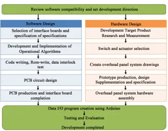
shows the development process of the main organization and participating companies.
2.1. Development Goals and Development Contents
DOI: 10.4236/wjet.2017.54059 710 World Journal of Engineering and Technology
Figure 2. Development target technology concept map.
Figure 3. Development process of the project.
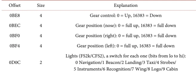
is a process of building a path. Each flight data have a categorized and unique data address as shown in Table 1.
[image:4.595.210.539.378.633.2]DOI: 10.4236/wjet.2017.54059 711 World Journal of Engineering and Technology
Table 1.FSUIPC data offset.
Offset Size Explanation
0BE8 4 Gear control: 0 = Up, 16383 = Down 0BEC 4 Gear position (nose): 0 = full up, 16383 = full down
0BF0 4 Gear position (right): 0 = full up, 16383 = full down 0BF4 4 Gear position (left): 0 = full up, 16383 = full down
0D0C 2 Lights (FS2k/CFS2), a switch for each one (bits from lo to hi): 0 Navigation/1 Beacon/2 Landing/3 Taxi/4 Strobes/ 5 Instruments/6 Recognition/7 Wing/8 Logo/9 Cabin
conjunction with flight simulation program through FSUIPC using the above program. Basic flight data can also be loaded. Developed Boeing 747 Overhead System utilizing SW and general purpose interface board.
2.2. Selection of Interface Board
The data communication protocol used in the development of this technology is serial port (RS-232), which is older than USB, but not restricted by the length of the connection line, cheap and the type of exchange information is irrelevant.
On the other hand, the universal interface board used in this technology de-velopment project is FDS-SYS1X and has 128 input and 256 output interfacing functions.
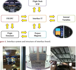
Each of the input switches and LEDs of the aircraft simulator operate as shown in Figure 4. After wiring the interface IT SYS card and I / O facilities, we write a code to associate input/output with each of SYS card using the functions of FSUIPC and Project Magenta [5].
2.3. Hardware Design
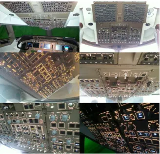
This is a part of Boeing 747 overhead system installation process. The structure has to be designed and the panel was matched according to the flight simulator internal layout. Overhead system location is measured using Boeing 747 FTD simulator, which is owned by Nuri Air Systems. Figure 5 shows the imported 747 overhead system does not fit with the simulator internal structure. We rede-signed the work and created the design drawing, using the actual aircraft data, as in Figure 6[6]. Figure 7 shows the completed overhead system pictures with all the switches, levers, and indicator lights working correctly.
Figure 8 and Figure 9 show the real-size Boeing 747 simulator made by Nuri Air Systems. The interior of the simulator exactly duplicates that of the real air-craft cockpit. We used the technical data of Boeing Company and every switch and button also replicate the real aircraft.
3. Integration of Hardware and Software
DOI: 10.4236/wjet.2017.54059 712 World Journal of Engineering and Technology
[image:6.595.216.531.401.529.2]Figure 4. Interface system and structure of interface board.
Figure 5. 747 Overhead panel installtion process.
[image:6.595.220.532.562.721.2]Figure 6. 747 Overhead system design drawings.
DOI: 10.4236/wjet.2017.54059 713 World Journal of Engineering and Technology
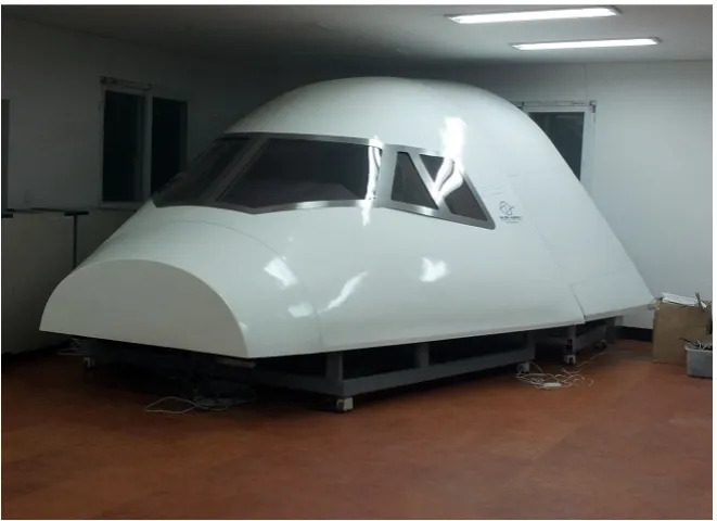
Figure 8. The exterior of the Nuri Air Systems Boeing 747 simulator.
Figure 9. The completion of the Nuri Air Systems 747-400 flight simulator.
inserted in the interface board. The switch and the rotary knob correspond to the input part, so they are connected to the input part of the interface. The LEDs indicating the operation status of each function are connected to the output part, as shown in Figure 10.
DOI: 10.4236/wjet.2017.54059 714 World Journal of Engineering and Technology
[image:8.595.267.481.262.502.2]Figure 10. Verification of overhead system wiring and data interlocking.
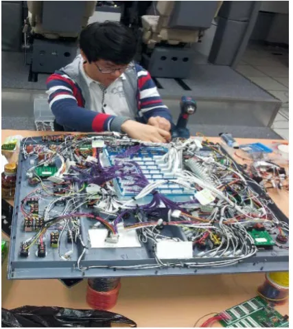
Figure 11. Wiring work.
[image:8.595.232.519.535.706.2]DOI: 10.4236/wjet.2017.54059 715 World Journal of Engineering and Technology
refer to the information from the actual aircraft data. The interface connector of each switch and the wiring of the LED output have been carefully constructed according to the design specifications. After checking the cathode and anode of the LED, we connected the 8 cathodes to the common GND and each anode to the pins of the interface board. We followed the procedure to finish the LED wiring and performed the correct operations according to the data interlocking.
4. Final Assembly and Integration
The completed overhead system is installed in the Boeing 747 simulator of par-ticipating company (Nuri Air Systems). We did final data interlocking test and operation test. We checked that all functions and found that the backlight func-tions are working normally. Figure 13 shows the completed assembly, which has been installed in the simulator cockpit.
The completed assembly has been evaluated in accordance with the National Transportation Test and Evaluation Standards [7] [8]. Table 2 shows the de-tailed evaluation table and the contents. The evaluation results shows the validity of the product.
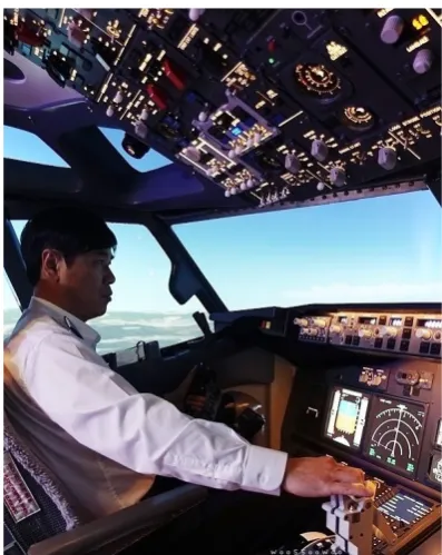
Figure 14 shows the final installation of the overhead system inside the cock-pit of the Boeing 747 simulator.
[image:9.595.210.539.394.708.2]As shown in Figure 15 and Figure 16, we have invited several commercial airline pilots and let them test fly the Boeing 747 flight simulator, which has
DOI: 10.4236/wjet.2017.54059 716 World Journal of Engineering and Technology
[image:10.595.232.516.286.428.2]Figure 14. Completed cockpit interior.
Figure 15. Preflight check of the completed Boeing 747 simulator.
[image:10.595.273.472.456.706.2]DOI: 10.4236/wjet.2017.54059 717 World Journal of Engineering and Technology
Table 2. Evaluation table.
Evaluation
(Interlocking) Unit (%) (Italy/Cp flight) World-class Domestic Target Method Figure Results
Light control OFFSET 10%
All functions
C A
Real time (±0.5 sec)
+0.2 sec A Normal operation Verifictation of Data
Data Linkage
Oxygen System OFFSET 10%
All functions
C A
Real time (±0.5 sec)
+0.1 sec A Normal operation Verifictation of Data
Data Linkage
Air control system OFFSET 10%
All functions
C A
Real time (±0.5 sec)
+0.2 sec A Normal operation Verifictation of Data
Data Linkage
Electrical control OFFSET 10%
All functions
C A
Real time (±0.5 sec)
+0.2 sec A Normal operation Verifictation of Data
Data Linkage
Fuel control OFFSET 10%
All functions
D A
Real time (±0.5 sec)
+0.1 sec A Normal operation Verifictation of Data
Data Linkage
Hydraulic system OFFSET 10%
All functions
B A
Real time (±0.5 sec)
+0.1 sec A Normal operation Verifictation of Data
Data Linkage
Engine start control OFFSET 10%
All functions
C A
Real time (±0.5 sec)
+0.1 sec A Normal operation Verifictation of Data
Data Linkage
Indicator OFFSET 10%
All functions
C A
Real time (±0.5 sec)
+0.1 sec A Normal operation Verifictation of Data
Data Linkage
Dimention mm 10% - B A (Tolerance ±0.5 mm) ±0.2 mm A
Verifictation of Data
*Evaluation Reference: Level & Target A (Excellent) > B (Good) > C (Fair) > D (Poor) > E (Unstable) > F (Fail). Method: The value (offset) Value between the switch and control board mounted on the overhead panel is connected to the data value (offset) value between S/W and H/W based on 747-400 FCOM (Flight Crew operation manual) and accuracy were evaluated. Signal interblocking time was measured with an interrogate tool.
DOI: 10.4236/wjet.2017.54059 718 World Journal of Engineering and Technology
ment will open up a new market and the export substitution effect will also oc-cur. We will continue to supplement and revise to export to the world market. After companies and universities participate in technology development, their technology will improve as well as the improvement of personal expertise due to a significant increase in human resource education. It is anticipated to be a subs-titute for imports through this development project. It is a product that can completely replace imports in terms of product price and performance as to the simulator market.
Acknowledgements
This work was supported by the Ajou University research fund.
References
[1] De la Torre, G.G., Ramallo, M.A. and Cervantes, E.G. (2016) Workload Perception in Drone Flight Training Simulators. Computers in Human Behavior, Computers in Human Behavior, 64, 449-454.https://doi.org/10.1016/j.chb.2016.07.040
[2] Liu, Z. and Li, H. (2006) Research on Visual Objective Test Method of High-Level Flight Simulator. Xitong Fangzhen Xuebao (Journal of System Simulation).
[3] Le-Ngoc, L. (2013) Augmenting Low-Fidelity Flight Simulation Training Devices via Amplified Head Rotations. Loughborough University.
[4] Lee, S. and Lim, K. (2008) PCB Design Guide Book. Sehwa Publishing Co., South Korea.
[5] Kang, M. and Shin, K. (2011) Electronic Circuit. Hanbit Media, South Korea. [6] Boeing 747-400 Operation Manual, Revision 21, The Boeing Co., Seattle, UAS,
2001.
[7] Kim, D., Kim, J. and Yoon, S. (2016) Development and Validation of Manned and Unmanned Aircraft Simulation Engine for Integrated Operation in NAS. Journal of the Korean Society for Aeronautical & Space Sciences, 44, 423-430.
[8] Kwon, Y., Heo, J., Jeong, S., Yu, S. and Kim, S. (2016) Analysis of Design Directions for Ground Control Station (GCS). Journal of Computer and Communications, 4, 1-7. https://doi.org/10.4236/jcc.2016.415001
[9] Beard, S., et al. (2014) Space Shuttle Landing and Rollout Training at the Vertical Motion Simulator. AIAA. Retrieved 5 February 2014.
DOI: 10.4236/wjet.2017.54059 719 World Journal of Engineering and Technology
[11] Taylor, H.L., Talleur, D.A., Emanuel Jr., T.W. and Rantanen, E.M. (2005) Transfer of Training Effectiveness of a Flight Training Device (FTD). Proceedings of the Symposium on Aviation Psychology, 13.
[12] Jeong, S., Heo, J., Yu, S., Lee, S. and Kwon, Y. (2016) Operation of UAV in the Hel-icopter Simulator to Assess the Mission Task Load (Experiment I). International Journal of Applied Engineering Research, 11, 8908-8915.
[13] Jeong, S., Heo, J., Yu, S., Lee, S. and Kwon, Y. (2016) Operation of UAV in the Hel-icopter Simulator to Compare the Control Interface Methods (Experiment II). In-ternational Journal of Applied Engineering Research, 11, 9111-9115.
[14] Tseng, T.-L., Ho, J.C., Lee, S. and Kwon, Y. (2016) Analysis of Complex PCB Design Data Using Data Mining Approach to Better Estimate the Work Hours. Interna-tional Journal of Applied Engineering Research, 11, 11700-11711.