DESIGN AND ANALYSIS OF AUTOMOTIVE CHASSIS CONSIDERING CROSS
*1
Vijayan, S. N.,
1
Department of Mechanical Engineering, Karpagam Institute of Technology, Coimbatore, India
2,3
Department of Aeronautical Engineering, Karpagam Institute of Technology, Coimbatore,
ARTICLE INFO ABSTRACT
The automotive chassis serves as a frame work for supporting the body and different parts of the automobile. Also, it has to withstand the shock, twist, vibration and other stresses caused due to sudden breaking, acceleration, shocking road condition, cent
induced by its components. The chassis acts as the backbone of a heavy vehicle which carries the maximum load for all designed operating conditions. This paper describes design and analysis of heavy vehicle chassis
world. In the present paper, the pertinent information of an existing heavy vehicle chassis of EICHER is taken for modeling and analysis by considering polymer composite materials
Epoxy, and cross
chassis. The numerical results are validated with analytical calculation considering distribution and
Copyright © 2015 Vijayan et al. This is an open access article distributed under the Creative Commons Att distribution, and reproduction in any medium, provided the original work is properly cited.
INTRODUCTION
Automotive chassis is a skeletal frame on which mechanical parts like engine, axle assemblies, brakes, steering etc, are fastened. Automotive chassis or automobile chassis helps to keep an automobile rigid, stiff and unbending. Chassis ensures low levels of noise, vibrations and harshness throughout the automobile. The chassis is considered to be the most significant component of an automobile. It is the most crucial element that gives strength and stability to the vehicle under different conditions. The backbone of any automobile, it is the supporting frame to which the body of an engine, axle assemblies are affixed. Tie bars, that are essential parts of automotive frames, are fasteners that bind different auto parts together. Automotive frames are basically manufactured from steel. It is usually made of a steel frame, which holds the body and engine of an automotive vehicle. It provid
needed for supporting vehicular components and payload placed upon it. At the time of manufacturing, the body of a vehicle is flexibly molded according to the structure of chassis. It provides strength needed for supporting vehicular components and payload placed upon it. Automobile chassis is usually made of light sheet metal or composite plastics. paper describes the design and analysis of heavy vehicle chassis considering weight reduction as the prime objective of any automobile industries in today’s fast changing world.
*Corresponding author: Vijayan, S. N.
Department of Mechanical Engineering, Karpagam Institute of Technology, Coimbatore, India.
ISSN: 0975-833X
Vol.
Article History:
Received 10th February, 2015
Received in revised form 21st March, 2015 Accepted 04th April, 2015
Published online 25th May,2015
Key words:
Chassis, S-Glass Epoxy, Stress, Deformation.
RESEARCH ARTICLE
DESIGN AND ANALYSIS OF AUTOMOTIVE CHASSIS CONSIDERING CROSS
AND MATERIAL
Vijayan, S. N.,
2Sendhilkumar, S. and
3Kiran Babu, K. M.
Mechanical Engineering, Karpagam Institute of Technology, Coimbatore, India
Department of Aeronautical Engineering, Karpagam Institute of Technology, Coimbatore,
ABSTRACT
The automotive chassis serves as a frame work for supporting the body and different parts of the automobile. Also, it has to withstand the shock, twist, vibration and other stresses caused due to sudden breaking, acceleration, shocking road condition, centrifugal force while cornering and forces induced by its components. The chassis acts as the backbone of a heavy vehicle which carries the maximum load for all designed operating conditions. This paper describes design and analysis of heavy vehicle chassis as the prime objective of any automobile industries in today’s fast changing world. In the present paper, the pertinent information of an existing heavy vehicle chassis of EICHER is taken for modeling and analysis by considering polymer composite materials
Epoxy, and cross-sections like C, I and Box type subjected to the identical load as that of a steel chassis. The numerical results are validated with analytical calculation considering
distribution and deformation.
is an open access article distributed under the Creative Commons Attribution License, which distribution, and reproduction in any medium, provided the original work is properly cited.
Automotive chassis is a skeletal frame on which mechanical parts like engine, axle assemblies, brakes, steering etc, are Automotive chassis or automobile chassis helps to keep an automobile rigid, stiff and unbending. Chassis ensures low levels of noise, vibrations and harshness throughout the The chassis is considered to be the most utomobile. It is the most crucial element that gives strength and stability to the vehicle under different conditions. The backbone of any automobile, it is the supporting frame to which the body of an engine, axle e essential parts of automotive frames, are fasteners that bind different auto parts together. Automotive frames are basically manufactured from steel. It is usually made of a steel frame, which holds the body It provides strength needed for supporting vehicular components and payload At the time of manufacturing, the body of a vehicle is flexibly molded according to the structure of chassis. It provides strength needed for supporting vehicular s and payload placed upon it. Automobile chassis is usually made of light sheet metal or composite plastics. This paper describes the design and analysis of heavy vehicle chassis considering weight reduction as the prime objective of
ies in today’s fast changing world.
Department of Mechanical Engineering, Karpagam Institute of
Many composite materials offer a combination of strength and modulus that are either comparable to or better than any traditional metallic metals. Because of their low specific gravities, the strength to weight
ratio of these composite materials are markedly superior to those of metallic materials. The fatigue s
well as fatigue damage tolerances of many composite laminates are excellent. For these reasons, fiber composite have emerged as a major class of structural material and are either used or being considered as substitutions for metal many weight-critical components in aerospace, automotive and other industries. High damping capacity of composite materials can be beneficial in many automotive applications in which noise, vibration, and hardness is a critical issue for passenger comfort. In the present work, the pertinent information of an existing heavy vehicle chassis of EICHER is taken for design and analysis with different cross sections for different materials like steel and S
The model of steel and polymeri
chassis was created in Pro-E and analysed with ANSYS for same load conditions. After analysis a comparison is made between existing conventional steel chassis and
in terms of deflections and stresses, to select the b
Literature Survey
Considering C, I and Box type cross sections, is analyzed by employing a polymeric composite heavy vehicle chassis for the same load carrying capacity, with a reduction in weight of 73% to 80% (Ravi Chandra et al.,
Available online at http://www.journalcra.com
International Journal of Current Research
Vol. 7, Issue, 05, pp.15697-15701, May, 2015
INTERNATIONAL
z
DESIGN AND ANALYSIS OF AUTOMOTIVE CHASSIS CONSIDERING CROSS-SECTION
Kiran Babu, K. M.
Mechanical Engineering, Karpagam Institute of Technology, Coimbatore, India
Department of Aeronautical Engineering, Karpagam Institute of Technology, Coimbatore, India
The automotive chassis serves as a frame work for supporting the body and different parts of the automobile. Also, it has to withstand the shock, twist, vibration and other stresses caused due to rifugal force while cornering and forces induced by its components. The chassis acts as the backbone of a heavy vehicle which carries the maximum load for all designed operating conditions. This paper describes design and analysis of as the prime objective of any automobile industries in today’s fast changing world. In the present paper, the pertinent information of an existing heavy vehicle chassis of EICHER is taken for modeling and analysis by considering polymer composite materials namely, S-Glass sections like C, I and Box type subjected to the identical load as that of a steel chassis. The numerical results are validated with analytical calculation considering the stress
ribution License, which permits unrestricted use,
Many composite materials offer a combination of strength and comparable to or better than any traditional metallic metals. Because of their low specific gravities, the strength to ratio and modulus to weight-ratio of these composite materials are markedly superior to
The fatigue strength weight ratio as well as fatigue damage tolerances of many composite laminates are excellent. For these reasons, fiber composite have emerged as a major class of structural material and are either used or being considered as substitutions for metal in critical components in aerospace, automotive and other industries. High damping capacity of composite materials can be beneficial in many automotive applications in which noise, vibration, and hardness is a critical issue for In the present work, the pertinent information of an existing heavy vehicle chassis of EICHER is design and analysis with different cross sections for different materials like steel and S-Glass Epoxy composite. The model of steel and polymeric composite heavy vehicle E and analysed with ANSYS for same load conditions. After analysis a comparison is made conventional steel chassis and S-Glass Epoxy in terms of deflections and stresses, to select the best one.
Considering C, I and Box type cross sections, is analyzed by employing a polymeric composite heavy vehicle chassis for the same load carrying capacity, with a reduction in weight of
et al., 2012). The determination of
the stresses in a truck chassis before manufacturing is important due to the design improvement and it is investigated (Hemant et al., 2013). Analytical investigation of the truck chassis design and the weight optimization was done by sensitivity analysis. In sensitivity analysis different cross sections were used for stress analysis and achieved 17% of weight reduction in the truck chassis (Hirak Patel et al., 2013). The stress analysis of chassis using finite element analysis was performed using ANSYS. The same finite element model can be used for the fatigue analysis of the chassis (Ashutosh Dubey and Vivek Dwivedi, 2003). Investigation of the structural analysis and optimization of vehicle chassis with constraints of maximum shear stress and deflection of chassis under maximum load was performed (Abhishek Singh et al., 2014).
The analysis using finite element techniques, weight of chassis frame can be optimized and it is feasible to analyse the modified chassis frame before manufacturing (Anand Gosavi
et al., 2014). The model for vehicle that considers the elastic
characteristic of frame was applied to the rear frame of articulated dump truck, it was confirmed that this analysis can be used to predict the bending and torsion stresses of frames (Haval Kamal Asker, 2012). The automotive chassis was optimized with constraints of maximum shear stress, equivalent stress and deflection of chassis under maximum load, also a sensitivity analysis is carried out for weight reduction (Monika, et al., 2013). The mathematical stress analysis of a platform integrated structure mounted on vehicle chassis designed for unconventional type of loading pattern was described (Deulgaonkar, 2012). The fatigue study and life prediction on the chassis in order to verify the safety of this chassis during its operation using Finite Element Method (FEM) was discussed in detail (Kurdi, et al., 2008). The modifications of existing bracket have resulted in reduction of stress values leading to safe design was investigated (Balbirsingh, et al., 2013).
The structural analysis of the chassis frame is performed to check the vulnerable points having high magnitude stress at static load condition (Paul et al., 2012). A detailed review was presented on the chassis design using FEA (Harshad et al., 2013). The stress analysis of heavy duty truck chassis was investigated for fatigue study and life prediction of components to determine the critical point having high stress (Roslan Abd Rahman et al., 2008; Goolla Murali et al., 2013). The static and dynamic load characteristics using Finite Element models are performed (Rajappan and Vivekanandhan, 2013). The analysis of chassis frame was done to improve its payload by adding stiffener at maximum stress region of chassis (Sairam Kotari and Gopinath, 1998). The effective method for dynamic stress analysis of structural components of bus systems is detailed (Kim et al., 2010). To determine the characteristics of a chassis using ANSYS and reinforcement technique of optimization is carried out (Sandip Godse, 2013).
The static and dynamic load characteristics of chassis were investigated using Finite Element Analysis method (Rajappan and Vivekanandhan, 2013; Tushar et al., 2013). The structural analysis of chassis was investigated by replacing traditional materials with ultra light weight carbon fiber materials (Salvi Gauri Sanjay et al., 2014).
Specification of Existing Heavy Vehicle Chassis
The specification of an EICHER 10.9 vehicle is exposed in the Table 1 The capacity of truck is 78480N, total load acting on the chassis including truck capacity, weight of the body and engine is 117720N. The load acting on each beam is half of the total load acting on the chassis hence load acting on single beam is 58860N
Stress σ=Mmax/Zxx ………..(1)
[image:2.595.307.574.227.335.2]Y= wx(b-x)/24EI [x(b-x)+ b^2- 2(c^2+ a^2 )- 2/b {c^2 x+ a^2 (b-x)} ] ………..(2)
Table 1. Specifications of heavy vehicle chassis
Structural Analysis of Heavy Vehicle Chassis
Dimensions of polymeric composite heavy vehicle chassis (PCHVC) are taken as that of the conventional steel heavy vehicle chassis (SHVC). Width of the chassis is 80mm. Since the properties of PCHVC vary with directions of fiber, a 3-D model of chassis is needed for analysis. The loading conditions are assumed to be static. The element has six degrees of freedom at each node translations in the nodal x, y, and z directions and rotations about the nodal x, y, and z-axes. The finite element analysis is carried out on steel chassis as well as different types of polymeric composite heavy vehicle chassis. From the analysis the stress distribution (Von-mises stress) and deformations were carried out. The total load of chassis of magnitude 58860N is applied on each side of beam and the gravitational force of 9806.6N is also considered.
RESULTS AND DISCUSSION
[image:2.595.339.530.579.730.2]Deformation Plot of C - Channel Section
Fig. 1. Deformation pattern for steel chassis channel
PARAMETERS VALUE
Material of the chassis Steel 52
Chemical composition 0.20%C, 0.50%Si, 0.9%Mn, 0.03%P and 0.025%S Side bar of the chassis 200mm x 76 mm x 6mm
Cross bar of the chassis 180mm x 75 mm x 4mm
Front Overhang (a) 935 mm
Wheel Base (b) 3800 mm
Rear Overhang (c) 1620 mm
Young’s modulus E 2 x 10⁵ N / mm2
Poisson Ratio 0.3
Fig. 2. Stress distribution for steel chassis
Fig. 3. Deformation pattern for S-Glass epoxy chassis
Fig. 4. Stress distribution for S-Glass epoxy chassis
[image:3.595.341.528.229.377.2]Fig. 5. Deformation pattern for steel chassis
Fig. 6. Stress distribution for steel chassis
[image:3.595.69.262.230.373.2]
Fig 7. Stress distribution for S-Glass epoxy chassis
[image:3.595.70.261.397.555.2]
Fig. 8. Deformation pattern for S-Glass epoxy chassis
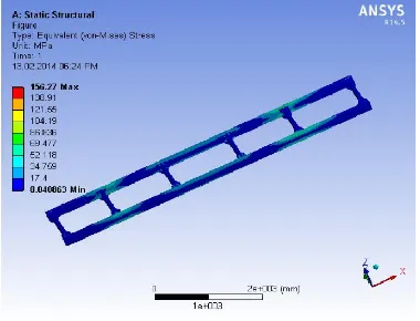
Structural Analysis of Box Channel Section
Fig 1 to 4 illustrates the deformation and stress distribution pattern for the C-channel cross section. Fig 1,3 represents the deformation plot for the C-channel cross section for the different materials. Fig 2,4 represents the stress distribution for the C-channel cross section for the different materials. The deformation and stress distribution pattern for the I- Cross section is depicted in the Fig 5 to 8. Figures 5,8 represents the deformation plot for the I-channel cross section for the different materials. Fig 6,7 represents the stress distribution for the I-channel cross section for the different materials. The deformation and stress distribution pattern for the Box- Cross section is depicted in the Fig 9 to 12. The deformation plot for the Box- cross section for the different materials is shown in fig 9,11.
15699 International Journal of Current Research, Vol. 7, Issue, 05, pp.15697-15701, May,2015
[image:3.595.336.532.408.556.2] [image:3.595.70.262.585.730.2]Fig. 9. Deformation pattern for steel chassis
[image:4.595.70.259.229.375.2]Fig. 10. Stress distribution for steel chassis
[image:4.595.71.259.407.555.2]Fig. 11. Deformation pattern for S-Glass epoxy chassis
Fig. 12. Stress distribution for S-Glass epoxy chassis
The stress distribution for the Box-cross section for the different materials is shown in Fig 10,12 The analytical results of stress distribution and deformation computed using equation 1 and 2 tabulated in the Table 2. Table 2 shows the stress distribution and deformation values for materials and cross section of different materials and compared with the analytical values. It can be inferred from the tabulation that the magnitudes of the deformation and stress are very closer to analytical results in comparison with the numerical results.
Table 2. Deformation and Stress Distribution Values
Cross Section
Material Type Stress DISTRIBUTION Deformation (mm)
Numerical Analytical Numerical Analytical
C Steel 230.58 235.0789 3.1272 3.214
S-Glass Epoxy 277.88 235.0789 13.941 13.561
I Steel 135.53 133.64 2.2570 2.349
S-Glass Epoxy 135.9 133.64 6.1079 6.530
BOX Steel 154.93 155.06 2.7396 2.833
S-Glass Epoxy 156.27 155.06 8.7955 8.912
[image:4.595.335.530.451.741.2]The magnitude of stress and deformation of steel are greater when compared to other polymer composites. When compared with C and Box cross sections the I cross section induces very low stress and deformation. S-Glass Epoxy material of C and BOX cross section as high stress and deformation when compare to I cross section. Fig 13 and 14 indicates the deformation and stress distribution curve for the analysis performed on various cross sections with different materials like steel and S-Glass Epoxy composite. From the above curve it is clear that S-Glass Epoxy polymeric composite induces high level of deformation and stress distribution when compared with steel. I-Cross section provides low deformation and stress distribution when compared to other cross sections like C and Box.
Fig. 13. Deformation curve
[image:4.595.70.260.586.731.2]Conclusion
The existing heavy vehicle chassis of EICHER is considered for design and analysis with different cross sections for different materials like S-Glass Epoxy composites is performed. The model of the chassis was created in Pro-E and analysed with ANSYS for same load conditions. After analysis a comparison is made between existing conventional steel chassis and S-Glass Epoxy composite materials in terms of deformation and stresses, to select the best one. The results of the steel and polymeric composites material with cross section C, I, and Box are performed. It is inferred that by employing a S-Glass Epoxy composites heavy vehicle chassis for same load carrying capacity, there is a reduction in weight when compared to steel but main downside is S-Glass Epoxy induces high deformation and stress distribution when compared to steel except in ‘I’ section. Based on the results it was inferred that steel with ‘I’ section has superior strength to withstand high load and induced low deformation and stress distribution when compared to S-Glass Epoxy composites material.
REFERENCES
Abhishek Singh, Vishal Soni and Aditya Singh. 2014. Structural Analysis of Ladder Chassis for Higher Strength:
International Journal of Emerging Technology and Advanced Engineering, Vol. 4. Issue. 2.
Anand Gosavi, Ashish Kumar Shrivastava and Ashish Kumar Sinha. 2014. Structural analysis of six axle trailer frame
design and modification for weight reduction:
International Journal of Emerging Technology and Advanced Engineering, Vol. 4. Issue. 1.
Ashutosh Dubey and Vivek Dwivedi, 2003. Vehicle Chassis Analysis: Load Cases and Boundary Conditions for Stress Analysis.
Balbirsingh, R., Guron, Dr. Bhope, D.V. and Prof. Yenarkar, Y. L. 2013. Finite Element Analysis of Cross Member Bracket of Truck Chassis: IOSR Journal of Engineering, Vol. 3, Issue. 3. PP. 10-16.
Deulgaonkar, V. R., Dr. Matani, A. G. and Dr. Kallurkar, S. P. 2012. Advanced Mathematical Analysis of Chassis Integrated Platform Designed for Unconventional loading by using simple technique for static load: International
Journal of Engineering and Innovative Technology, Vol. 1.
Issue. 3.
Dr. Rajappan, R. and Vivekanandhan, M.2013. Static and Modal Analysis of Chassis by Using FEA: The
International Journal Of Engineering And Science, Vol. 2.
Issue. 2. Pp. 63-73.
Dr. Rajappan, R. and Vivekanandhan, M.2013. Static and Model Analysis of Chassis By Using FEA: Proceedings of the National Conference on Emerging Trends In Mechanical Engineering.
Goolla Murali, Subramanyam, B. and Dulam Naveen.2013. Design Improvement of a Truck Chassis based on Thickness: Altair Technology Conference. India.
Harshad, K., Patel, Prof. Tushar, M. and Patel.2013. Structural Optimization Using FEA-DOE Hybrid Modeling –A Review: International Journal of Emerging Technology
and Advanced Engineering, Vol. 3. Issue. 1.
Haval Kamal Asker, Thaker Salih Dawoodl and Arkan Fawzi Said. 2012. stress analysis of standard truck chassis during Ramping on block using finite element method: ARPN
Journal of Engineering and Applied Sciences, Vol. 7. No.
6.
Hemant, B., Patil, Sharad, D., Kachave, Eknath, R. and Deore. 2013. Stress Analysis of Automotive Chassis with Various Thicknesses: IOSR Journal of Mechanical and Civil
Engineering, Vol. 6. Issue. 1. PP. 44-49.
Hirak Patel, Khushbu, C., Panchal, Chetan S. and Jadav. 2013. Structural Analysis of Truck Chassis Frame and Design Optimization for Weight Reduction: International Journal
of Engineering and Advanced Technology, Vol. 2. Issue. 4.
Kim, H. S., Hwang, Y. S. and Yoon, H. S. 2010. Dynamic Stress Analysis of a Bus Systems: Commercial Vehicle Engineering & Research Center. Hyundai Motor Company. 772-1, Changduk. Namyang. Whasung. Kyunggi-Do. Korea.
Kurdi, O., Abd- Rahman, R. and Tamin, M. N. 2008. Stress Analysis of Heavy Duty Truck Chassis Using Finite Element Method.
Monika, S., Agrawal, Razik, Md.2013. Finite Element Analysis of Truck Chassis: International Journal of
Engineering Sciences & Research Technology, Agrawal.
2(12).
Paul, I. D., Sarange, S. M., Bhole, G. P., and Chaudhari, J. R.2012. Structural Analysis Of Truck Chassis Using Finite Element Method: International J.of Multidispl.Research
and Advcs. in Engg., Vol. 4. No. I. pp. 85-98.
Ravi Chandra, M., Sreenivasulu, S. and Syed Altaf Hussain. 2012. Modeling and Structural analysis of heavy vehicle chassis made of polymeric composite material by three different cross sections: International Journal of Modern
Engineering Research, Vol. 2. Issue. 4. pp. 2594-2600.
Roslan Abd Rahman, Mohd Nasir Tamin and Ojo Kurdi.2008. Stress Analysis Of Heavy Duty Truck Chassis As A Preliminary Data For Its Fatigue Life Prediction Using Fem: Jurnal Mekanika. No. 26. PP. 76 – 85.
Sairam Kotari, Gopinath, V. 1998. Static and Dynamic Analysis on Tatra Chassis: International Journal of
Modern Engineering Research, Vol. 2. Issue. 1. Pp.
086-094.
Salvi Gauri Sanjay, Kulkarni Abhijeet, Gandhi Pratik Pradeep and Baskar, P.2014. Finite Element Analysis of Fire Truck Chassis for Steel and Carbon Fiber Materials: Journal of
Engineering Research and Applications, Vol. 4. Issue. 7.
Version. 2. PP. 69-74.
Sandip Godse and Prof. Patel, D.A.2013. Static Load Analysis Of Tata Ace Ex Chassis And Stress Optimisation Using Reinforcement Technique: International Journal of
Engineering Trends and Technology, Vol. 4. Issue. 7.
Tushar, M., Patel, Dr. Bhatt, M. G., and Harshad, K. and Patel. 2013. Analysis and validation of Eicher 11.10 chassis frame using Ansys: International Journal of Emerging
Trends & Technology in Computer Science, Vol. 2,
Issue. 2.
*******
15701 International Journal of Current Research, Vol. 7, Issue, 05, pp.15697-15701, May,2015