Abstract - For a specific method of data communication in industrial environments we are looking for options to detect the topology without changing the system setup or modifying the transmission protocol. A special requirement in this application represents the transfer of data and power supply via a simple unshielded two-wire line. The systems topology allows line, tree, star and ring structures with a total cable length of up to 200 meters. When using a multi-carrier modulation scheme for the communication, an active driven bus coupling of all clients is mostly assumed. In this case no statements about the position of the client could be evaluated only by the signal attenuation and propagation time. Studies based on real prototypes offer a lot of relevant test cases under nearly industrial conditions and the obtained experiences and results could be used for future industrial communication protocols, and new generations of system specific integrated circuits.
Keywords - industrial communication systems, topology
detection, unshielded two-wire line, multi carrier allocation
I. INTRODUCTION
n recent years, the need of more transmission capacity and bus participants is increasing. Industrial plants become more and more complex. Analyzing the currently used industrial communication standards, conspicuously that the transfer of user data and system power over a single communication medium is only used for connecting devices in the field level.
For this reason, only fieldbus systems connecting sensors and actuators over a simple unshielded two-wire line for system power and data transmission should be considered. For these systems it is not uncommon to use topologies up to 200 m line length and to handle with topology changes through plant construction expansion while plant operation. In addition to new developments of data transmission techniques, the use of time based serial analog signals is not longer preferred. Instead the use of parallel frequency based and digital signal transmission in new applications is increasing. This paper should disclose possible options to detect the line length, the topological expansion including line stubs and device positions in an unknown system.
Manuscript received July 11, 2014; revised August 12, 2014.
All Authors are employees of the HTWK Leipzig, Wächterstr. 13, 04107 Leipzig, Germany, ([email protected], [email protected], [email protected]@ftz.htwk-leipzig.de, [email protected]@ftz.htwk-leipzig.de, www.ftz-leipzig.de) or former student of the HTWK Leipzig (Christian Seidemann)
We are looking for technical measurement and system verification methods of actually existing bus configurations, line installation, topology violation and cable damages in wide branched fieldbus networks. Confronted with the safety aspect, the connection of additional periphery should also be detectable. Furthermore we are searching for simulation models, which can be used for the detection of worst-case topology scenarios. Especially when using a modified orthogonal frequency-division multiplexing (OFDM) in wide branched fieldbus topologies, there are device positions with imaginable unfavorable signal behavior. At these positions the number of usable carriers and their quality is minimized through system impedance and signal superposition. The result can be a total signal lost. Therefore a method is sought, to avoid these topological worst-case scenarios previously named.
II. POINT-TO-POINT SIGNAL PROPAGATION TIME MEASUREMENT
In the considered bus structure, all participants are connected to the same medium. The respective signal propagation time, therefore only depends on the used medium and the distance of the participants. Additionally when conclusions about the measured signal attenuation can be introduced, a more precise statement about the distance between the bus participants is possible. In the text below, the bus participants are separated in one master and many clients.
When only considering a serial connection between the master and one client, the signal propagation time can be determined directly from the transmitted user data. For this, the client must be addressed and the time measured until his answer arrive the master. Here, the time for creating the response in the client must be known and subtracted.
If the clients are not only built out of pure logic, but realized with controllers using software stacks, a client unique response time cannot be assumed. The measured signal propagation time is then jittering.
For serial bus topologies with a serial communication protocol and only a few bus participants connected in huge distance to each other, position detection via signal propagation time is a possible option.
The signal propagation time τ can be defined by the cable length l and the phase velocity νPh according to equation 2.1,
wherein the phase velocity is addicted to the frequency. However, a constant phase velocity is assumed.
(2.1)
Using many clients installed in a control cabinet, closely spaced to the neighbor client, propagation time measurement for exact position detection with sufficient
Analyzing Methods for Topology Detection on
Multi-Flexible Bus Systems
Tobias Rudloff*, Dietmar Telschow*, Martin Flügge*, Christian Seidemann*, Tilo Heimbold*
accuracy is almost impossible. In addition, these determined distances are not to be confused with the actually wanted topological position. Because the result of a pure propagation time measurement still does not represent the exact topology mapping of the system. You only know the distance between the master and the client, but there are still several topological options. This is schematically shown in Fig. 1. All three variants are identical in the length between master and the clients C1 up to C6.
Fig. 1. possible structures with identical length between master and clients
[image:2.595.306.553.260.386.2]A complicating factor continues to the dynamic, adaptive gain control of the clients physical bus interface. So the possibility of a runtime measurement using the determined attenuation factor is almost impossible. This conventional measurement method of the signal propagation time also seems to be not very effective for a data transmission using OFDM-DMT. Using this modulation type, the clients are supposed to send parallel instead of serial answers. In Fig. 2 such a communication cycle is shown with a master request followed by a response of a client group.
Fig. 2. communication cylces for a multi-carrier modulation (request from master – response from x clients)
For this reason the reflection behavior is to be considered when injecting a pulse into the inactive system. The pulse measurement and normal data traffic would significantly interact trying thisin the active mode.
III. REFLECTION BASED PROPAGATION TIME MEASUREMENT ON TWO WIRE LINES
For the active method of a reflection based signal propagation time measurement, the principle of the returning wave is used. This method is mainly used for simple point-to-point connections. When adapted to a topological wide branched bus system, several significant striking patterns within the measurement series are expected. So the idea is to filter out dedicated areas as a
result of reflections for example the beginning of a branch line, cable contusions or the bus client position through their mounting.
While now very short lines could be accepted as almost lossless, the line losses through a long cable (up to 200 m in the analyzed system) are significant. Furthermore, the various cable parameters have to be considered. While, in the present case always an unshielded two-wire cable is assumed, the wire cross-section can vary for the cable. Mixed networks with different cable types are also possible. Probably this is even the assumed industrial standard.
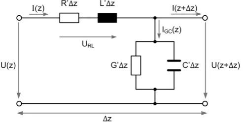
However, the now considered transmission line should be initially seen as longitudinally homogeneous, that means the line cross-section remains constant over the field of observation. With the help of the line equivalent circuit diagram shown in Fig. 3 the needed equations for our consideration can be derived.
Fig. 3. Line equivalent circuit of a short two-wire line segment
According to transmission line theory, the cable characteristics can be summarized by the complex propagation constant according to equation 3.1. Wherein the real part α reflects the attenuation constant and the imaginary part β the phase constant.
(3.1) The length of a line segment between two bus participants can be determined in different ways. One possible option is to determine the attenuation coefficient α and calculate the length and signal propagation time based on the signal attenuation.
The propagation speed of a signal running through a lossy line can also be represented by equation 3.2. For high and very high frequencies G' and R' will be vanishingly small. The line behavior now corresponds to a lossless line. In the case under consideration, the cable loss must be included.
(3.2)
It can be seen, that the signal propagation velocity is always seen as a function of its frequency. What can conclude from the description? That means a signal presented by a superposition of many other periodic signals will be distorted through different propagation speeds.
[image:2.595.49.293.438.572.2]Fig. 4. pulse distortion on a two-wire transmission line
IV. CHOOSING THE RIGHT PULSE FORM
The steeper the edges of the pulse, the more harmonics in the fourier spectrum are required for its synthesis.
During the pulse generation, the relation between pulse and silent period is controlling the intensity. The higher frequency ratios make the pulse edges steeper rising (Eq. 4.1).
∑
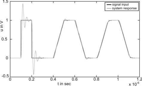
(4.1)The very high frequency ratios of a pulse with infinitely steep rise cannot or only complicated transmitted. Because the line thereby acts as a low-pass, these frequency components are dramatically reduced in their amplitude by the cable properties. For this reason, the pulse shape should be slightly flattened. In a simulation Figure 5 shows the named behavior. It demonstrates a clear overshoot at very steep rising edges. This fact makes a signal evaluation very difficult when using a reflection measurement method on a wide branched bus system.
Fig. 5. two-wire line system response supplying different pulse forms
If a selection is made and this pulse shape is impressed on a line with n clients, the high frequency signal parts are reflected in variable ways depending on the line impedance, cable breakouts and the physical connection of the clients. However, only a percentage of the signal is reflected. The rest will be transmitted. The following applies now: The sum of the amounts of reflection and transmission must be 1. The absolute value of the reflected signal is depending on the reflection factor, but also on the position of the client, because the pulse is greatly attenuated by the resistive losses. Plus, the amount of the reflected signal depends on the number of additional clients which are also between the
sender and the investigated client. The pulse takes reflections and transmissions on any client and every time between two clients. Figure 6 shows the results of a measurement on an 8.5 m long two-wire cable with and without clients, measured at the beginning and the end of the line. Here can already be seen that it is possible to identify cable length, branches and additional clients through significant wave form areas.
Fig. 6. pulse measurement on a 8.5m long unshielded two-wire line (sending end (top) and line end (bottom))
It could be possible to infer the position of individual clients on a short line and only a few widely distributed clients by using the pulse reflection method. For systems with more extensive cabling and many clients the number of appearing signal superposition from reflections occurring at and between the clients and line ends will rise enormous. Due to the resulting overlays, terminations and the real dominant signal loss through the cable, the requirements on simulation systems, algorithms, accurate and high resolution measurement will rise.
For systems transmitting high frequency signals, matched termination impedance is usually mounted to prevent precisely the backward signal waves.
Even in the observed bus system is the possibility to close up the system with such a termination impedance to be nearly free of reflection, but it is not officially specified.
In this case, with optimally matched termination impedance it is not feasible to measure any reflections in the installed sensor actuator network. Reflection measurement is only possible with open or shorted line ends.
V. PROBLEMS USING LINE STUBS AND MANY CLIENTS By the attachment of a new bus client the impedance distribution of the line is influenced if the client properties are not identical with the cable properties.But this cannot be assumed. The impedance, the attenuation and the propagation speed of the system will change. An impedance adjusted bus system will be badly influenced by adding a new component equal it is a new line segment or a new client. The line is now impedance mismatched and reflections will appear again.
[image:3.595.310.551.153.347.2] [image:3.595.51.289.483.629.2]Judging from a cable given signal delay of about 5.5 ns/m a possible length resolution of about 4.5 m is offered.
A theory suggests that the capacity of a very short branch line will still be charged while a pulse is starting to pass the position of the stub. When the pulse is leaving the branch position the stubs capacity is discharged slowly and no reflection appear. This applies only if the pulse width is greater than the stub length [8]. Figure 7 illustrates this schematically. Theoretically, very short connection wires of the clients should cause no reflections, if the pulse width is over a defined minimum width. It should be possible to mask out different short line stubs during a measurement recording when varying this width.
To follow this theory a practical evaluation of a measurement series with different pulse widths and stubs is to perform. It is also to evaluate what the maximal measurable branch length is what length of branch is possible to mask out. But this has to be checked in more detail.
Fig. 7. branch line reflections of different pulses
The reflection behavior of a pulse will now be more examined for further theoretical considerations. For the next derivations a one side terminated line segment should be the basis. At a user defined position in a one side terminated line the amplitude of a signal should be the superposition of the incoming and the reflected wave.
(5.1)
For the voltage Uh applies:
(5.2)
for Ur similarly applies:
(5.3)
Where ZL is the impedance of the line, U0 and I0 represent
the voltage and current at the reflection position. By inserting the equation 5.2 and 5.3 in equation 5.1 the following derivation for the reflection factor r at the location l can be used:
(5.4)
A closer look to the equation 5.4 and the reflection factor at the line end is now defined by
(5.5)
at the beginning of the line (l=0)
(5.6) The relation between ra and re applies to the following
formal context:
(5.7)
For a simplified representation of the reflected pulses on every client the following simplified derivation is used. Assuming that the amount of reflection and transmission at a client have to be 1 the following calculation order was created. This is only guilty for considering a lossless line.
For an easy treatment of the amplitude behavior of the reflected pulse under the condition that the impedance losses are insignificant small the following formal expression is used for a simulation.
∏ ∗ 1 ∀ ∈ : 2
1 ∃! ∈ : 1 (5.8)
Where δin is the Kronecker delta with the characteristic
1,
0, (5.9)
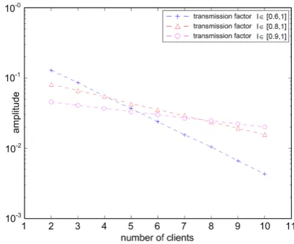
If all transmission factors have the same amount, then the expression simplifies to
Fig. 8. Expected values of the reflected amplitude by the n-th client
Fig. 9. Expected values of the reflected amplitude after n clients at the end of the line
VI. THE CLIENTS PHYSICAL INTERFACE CONNECTION On every local change of the cable characteristic, the so called discontinuity leads to a partial or complete reflection. That means this occurs at each client and each branch. The larger the cable capacitance, the slower the signal spreads out. A modified cable cross-section affects the cable capacitance and must be included in the considerations.
In the present case, the cable capacitances are additionally influenced by the capacitive loads of the connected clients. In Figures 10 and 11 the previously mentioned dynamic adaptive gain control for the client transmitter and receiver circuit is schematically shown. Statements about the capacitive or inductive loading of the line through the connected clients with complex impedances are very difficult. Because of the manufacturer-specific differences and the production tolerances every client will differently impact on the line parameters.
The considered reflection measurement with specific Dirac pulses for the topology analysis of a bus system is crucially influenced by the following parameters:
the pulse shape, and in particular the rise time and the resting time,
the frequency, if necessary the repetition, the topology (line, tree usw.),
the injection position, maybe several possible positions in tree structures
the impedance of the overall system vs. individual clients.
Fig. 10. Used transmitter design
[image:5.595.61.275.245.421.2]Experiments have shown, the reflection measurement at very high impedances of individual clients in relation to the entire system impedance (many clients) can be improved significantly through an aimed activation of capacitive bypass in the clients power supply. Remember, power supply and data transmission via the same medium. Furthermore, switchable active branches would simplify the topology analysis. This leads to additional costs and reduced reliability of the system components and is not considered as useful.
Fig. 11. Used receiver design
The investigated reflection method can be applied only in the offline mode of the system, which means without any bus communication. It is limited in terms of the ascertainable bus topology in the cable length or the clients distance by the timing resolution of the reflection signal. However, more detailed studies on this should still be conducted. It currently seems like a pure runtime or reflection measurement is not sufficiently accurate.
VII. TRANSIT TIME MEASUREMENT USING THE MODULATION PROCESS
As already mentioned, a data transmission via the unshielded two-wire cable should be practiced with a special form of a multi-carrier modulation scheme, the so called OFDM-DMT. Here, several sub-carriers are modulated for each client. The transmission frame is divided into a downlink (master to clients) and an uplink (clients to master) phase. This allows the possibility for multiple clients to send parallel after synchronization via a special trainings sequence. Figure 2 illustrates a transmission frame of the prototyping system. Using a data modulation based on figure 2 it is already apparent that a conventional metrological distance measurement of the signal propagation time is not possible. So other methods are needed.
[image:5.595.309.556.352.433.2]inherently used in the time domain. In the frequency domain it corresponds to the SI function. This rectangle function has harmonics on neighboring frequencies, thus interfere with other frequency bands. In order to avoid an overlap of the other frequencies, the upper and lower sub-carriers are not modulated. In addition, the width of the rectangle in the time domain is increased, to decrease the main lobe of the SI function. To avoid also intersymbol interferences, a guard interval before each symbol is additionally required. This is used to guarantee that a new symbol, significantly attenuated by line reflections and line length, is not influenced by the previous symbol. Finally in order to be able to transfer data over the channel medium, the generated signal must be a real one. For this, the subcarriers are chosen that the results are purely real after using an Inverse Discrete Fourier Transformation (IDFT). In theory, the transmitted symbols are attenuated and phase rotated by a special factor while passing the transmission channel. This factor is proportional to the signal propagation time. Here certain sub-carriers of the DQPSK reference symbols are used to determine the phase rotation. The use of this phase angle should enable the calculation of the signal propagation time.
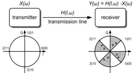
According to equation 6.1, a from the master received symbol Y(ω) is composed by the client transmitted symbol X(ω) and the line transfer function H(l,ω).
∙ , ∙ ∙ ∙ ∙ ∙ (6.1)
Wherein 1/2e-α represent the attenuation and e-jωl/vPh the
phase rotation of the symbol. For the here used weakly damped line, the phase rotation can be approximately captured. Furthermore, it is assumed a constant system phase velocity vPh. Figure 12 illustrates the relation between
the symbol transmission, the transmission line influences and the resulting phase rotation.
[image:6.595.61.277.561.678.2]With this method, a propagation time measurement has serious limitations. To get all the necessary information a defined interface to the master is needed, to read out the system internal carrier management information. This requirement for direct intervention in the systems architecture (thus also in the structure of later produced ASIC design) is the biggest obstacle for using a method like that. Also the accuracy of this method in respect of the client position has to be evaluated more in detail.
Fig. 12. schematic model of the transmission channel
VIII. CONCLUSION AND FUTURE WORK
In principle, through the use and combination of the presented methods it should be possible to venture statements respective an unknown topology. The maximum cable length, the number of participants and branches a measurement method can detect remains at present still
open. In any case more profound studies with different topologies and client properties are necessary. Also, presently there is not enough information about the required accuracy and error rate of the presented methods for a topology detection of a wide branched bus system realized with an unshielded tow-wire cable medium. At this time only a few clients are connected in a test construction with a used cable length of only up to 20 m and simply one short branch. So, to test more possible topologies, more time is needed. A much more sensitive and nearly nonreactive measurement interface for the cable connection is under construction. Assumedly, there is a need to sample measurement data in a higher resolution and sampling rates.
It appears to be appropriate, that only a combination of propagation time and pulse reflection measurements on the inactive System in conjunction with measurements of the symbol phase rotation during the active system operation permits a sufficient and valid number of measured data. Most likely the measurement is also carried out several times at different cable positions. Maybe a triangulation at three positions is useful, for example at the beginning, the main line end and at the end of a branch. But this could be a problem for future plant measurements, due to the difficult and obstructed cable access.
If it is possible to develop a measurement and testing method for a topology detection of a far branch and unshielded two-wire bus system, new wide ranging fields of application would appear.
The authors believe that the required effort to create complex simulation and calculation models is still a considerable research and investigation effort at the present time.
REFERENCES
[1] G. Schnell, “Bussysteme in der Automatisierungstechnik – Grundlagen und Systeme der industriellen Kommunikation” Braunschweig/Wiesbaden: Vieweg Verlag, 2012.
[2] VDI Standard 3687, “Selection of field bus systems by evaluating their performance characteristics for industrial applications” Berlin: Beuth-Verlag, 1999.
[3] J. A. C. Bingham, “Multicarrier modulation for data transmission: an idea whose time has come.” IEEE Communications Magazine, Vol. 28, Nr.5, pp. 5 -14, May 1990.
[4] I. Kalet, “The multitone channel” IEEE Communications Magazine, Vol. 37, Nr.2, pp. 119-124, February 1989.
[5] M. H. Hayes, “Statistical Digital Signal Processing and Modeling” John Wiley & Sons, 1996.
[6] R. Schur, “Impulse compression for OFDM transmission over time-varying multipath channels” IEEE Vehicular Technology Conference (VTC), September 2002.
[7] D. M. Welton, “Transmission Lines: Theory, Types and Applications” (Electrical Engineering Developments) [Hardcover], Nova Science Pub Inc, pp. 221-236, November 2011.
[8] Prof. Dr. Rainer Thüringer, „AVT: HighTech-/HighSpeed-Baugruppe - Skript Kapitel 2 – Impulse auf Leitungen“, FH Gießen-Friedberg
[10] F. Gustrau, „Hochfrequenztechnik - Grundlagen der mobilen Kommunikation“ 2. Auflage. München : Carl Hanser Verlag, 2013 [11] K. Küpfmüller; W. Mathis; A. Reibiger, Theoretische Elektrotechnik
-Eine Einführung. 18. Auflage. Berlin Heidelberg : Springer, 2008 [12] F. Strauss, „Grundkurs Hochfrequenztechnik - Eine Einführung“
1.Auflage. Wiesbaden : Vieweg Teubner Verlag, 2012
[13] Kammeyer, Karl-Dirk: „Nachrichtenübertragung“ Teubner, 3. Auflage, 2004.
[14] Handte, T.; Breuninger, M.; Hagmeyer, H.T.; Speidel, J.: „Physical layer of a novel broadband low-level fieldbus with discrete multitone“ In Factory Communication Systems (WFCS), 2012 9th IEEE International Workshop on, S. 173–176, May 2012.