Data Gathering System in Sensor Network
Ogwueleka Francisca Nonyelum, Adeoye Olamide Olayinka, Eze Udoka Felista, Odirichukwu Jacinta Chioma
Abstract-Network lifetime, scalability and load balancing are
important requirements for data gathering sensor network applications. A major issue is the technique used for data collection and data gathering. Many protocols were introduced for better performance. LEACH, PEGASIS and TREEPSI were used as established energy-efficient routing protocols. This paper proposes as efficient approach for data collection in wireless sensor networks by introducing an energy efficient priority algorithm (EEPA) model, which is a hybrid model, derived from a combination of LEACH and Member Forward List technique to enhance the cluster-head selection process. This priority algorithm model list includes the nodes with highest priority for forwarding the data. When a node fails or dies, this list is used to select the next node with higher priority. The EEPA prevents the traditional LEACH algorithm cluster-head selection algorithm from repeating when a node fails or dies. The result show that EEPA decreases power consumption and energy loss in wireless sensor networks.
Keywords: cluster-head selection, energy efficient priority algorithm, LEACH algorithm, member forward list technique, wireless sensor network
1. INTRODUCTION
Wireless sensor network (WSN) is a network consisting of small sensors with low-power transceivers that can be effective tool for gathering data in different environments. As sensor nodes are deployed in sensing field, they help to monitor and aggregate data. Researchers have tried to find more efficient ways of utilizing limited energy of sensor node in order to give the network a longer life span. LEACH, PEGASIS and TREEPSI have been used as established energy-efficient routing protocols. Observation and interpretation of natural phenomena has always been of fundamental importance to numerous research areas but data gathering in such conditions has been very difficult. The advent of wireless sensor networks however promises an unprecedented opportunity to monitor the physical environment through wireless devices. Sensor networks provide the possibility to sample and gather data at scales and resolutions, which were difficult to obtain earlier. By spreading large numbers of cheap untethered sensor nodes in an area of interest, scientists are enabled to monitor dense temporal and spatial data over an extended period of time [1]
Paper submitted 25 January, 2016, revised 20 April 2017. Sponsor: Tertiary Education Trust fund
F. N. Ogwueleka is with the Department of Computer Science, Federal University Wukari, Nigeria ([email protected]).
O. O. Adeoye is with the Department of Computer Engineering, Federal University of Technology Minna, Nigeria ([email protected]).
U.F. Eze is with the Department of Information Management Technology, Federal University of Technology Owerri, Nigeria ([email protected]).
J. C. Odirichukwu is with the Department of Computer Science, Federal University of Technology Owerri, Nigeria ([email protected]).
These nodes are capable of wirelesscommunications, sensing and computation (software, hardware,algorithms). It is clear that wireless sensor networkis the result of the combination of sensor techniques,embedded techniques, distributed information processing, and communication mechanisms [3]
A wireless sensor network(WSN) can also be described as a network that is made of hundreds or thousandsof sensor
nodes which are densely deployed in an
unattendedenvironment with the capabilities of sensing,
wireless communications and computations [3].
Applications running on such platforms must generally adapt their behaviour in response to user tasks, sensed information, dynamicchanges in connection topology and temporary/permanent problems withthe nodes and communications links present in the network.
The networking capability of WSNs is built up inlayers. The lowest layer controls the physical radiodevice. Radios are by nature a broadcast medium, when one node transmits, a collection of otherscan receive the signal unless it is garbled by othertransmissions at the same time. To avoid contendingfor the radio channel, the link layer listens onthe channel and transmits only when the channelis clear. It transmits a structured series of bits thatform a packet encoded in the radio signal.When not transmitting, nodes sample the channeland scan for a special symbol at the start of apacket that also lets the receiver align itself withthe sender’s time. The packet layer managesbuffers, schedules packets onto the radio, detectsor even corrects errors, handles packet losses, anddispatches packets to system or application components [4].
Sensor network nodes typically consist of six components: processor, radio, local storage, sensors and/or actuators, and power supply [5]. There are a number of relevant technology trends that have to be considered for example, a hugevariety of powerful low-power, low-cost processors, and low-cost memory technologies.Both memory and processor are growingmore and more powerful according to Moore's Law and wirelessbandwidth has increased by a factor of more than hundred in the last seven years yet, the capacity of batteries is onlygrowing at a rate as low as 3% per year. The cost of application-specific designs is growing rapidly: the cost of masks alone is one million dollars and keeps increasing by the factor of two every two years. Sensors and actuatorsare relatively young industrial fields and predictions are still uncertain [5].
communicates with the user viainternet or satellite communication. It is located near thesensor field or well-equipped nodes of the sensor network.Collected data from the sensor field routed back to the sinkby a multi-hop infrastructure less architecture through the sink [3].
The design factors and challenges for wireless sensornetworks’ protocol are energy depletion, robustness to dynamicenvironment, and scalability to numerous number ofsensor nodes. Some recommended solutions to these
challengesare reduction in the active duty cycle foreach
sensor node, a minimization of data communicationsover the wireless channel (i.e., aggregation, communicatenetwork state summaries instead of actual data), and maximizationof network lifetime (i.e., minimum energy routing)will give hand to the energy depletion challenge. Scalability on another hand, may be enhanced by organizing networkin a hierarchical manner (e.g., clustering) and utilizinglocalized algorithms with localized interactions amongsensor nodes, while robustness to environmental changes, may be improved through organizing, healing, self-configuring, and self-adaptive networks [3].
There are different ways by which the sensornetworks’ routing protocols can be classified. According to network structure, these routing protocols can be classified as flat,
hierarchical,and location-based protocols. These
protocolscan be classified into multipath-based, query-based, negotiation-based Quality of Service (QoS)-query-based, or coherent based depending on the protocol operation. Moreover, theseprotocols can be classified into three categories, namely, reactive, proactive, and hybrid protocols depending on routediscovery. In flat-based routing, all nodes are assigned thesame roles or functionalities. In hierarchical-based routing,nodes will play different roles or functionalities, aiming atrouting techniques clustering the nodes with different rolesso that the heads of the cluster can do some data aggregationor confusion in order to save power, while in location based routing; sensor nodes’ positions are exploited to routethe data to specific regions other than the whole network.On the other hand; in reactive protocols, routes are computedon demand. In proactive protocols, routes are computedbefore they are needed, while hybrid protocols utilizea combination of the ideas of both reactive and proactiveprotocols.
Flooding according to [6] is an old routing mechanism that may also beused in sensor networks. In flooding, a node sends out thereceived data or the management packets to its neighborsby broadcasting, unless a maximum number of hops for thatpacket are reached or the destination of the packets is arrived.Gossiping protocol is an alternative to flooding mechanism.In gossiping, nodes can forward the incoming data/packetsto randomly selected neighbor node.
Routing in sensor networks is different from the traditional wireless ad hoc networks due to the unique requirements of sensor networks [7]). Considering the energy awareness and time complexity forperiodic data collection application, hierarchical routing protocols perform better than other solutions [8]. Among the hierarchical category is Low-Energy Adaptive Clustering Hierarchy (LEACH) [9] which is a simple approach to collect data from sensor nodes. It is a direct approach where each sensor nodes transmit the data
directly to the base station (BS) which is located far away. The cost to transmit data from each sensor node to the BS is very high, thus nodes die quickly and hence reducing the lifetime of the network. Therefore, to utilize energy efficiently, the goal is to use as few transmissions as possible.LEACH Protocol is designed where sensor nodes are organized to form local cluster with one node in the cluster selected as cluster head. Sensor nodes from one cluster send data to its cluster head where data is aggregated and fused data is transmitted to BS. Cluster heads are chosen randomly and achieve a factor of 8 improvements compared to direct approach. Although LEACH protocol reduces energy consumption by factor 8, energy is greatly consumed in forming cluster [10].
Power-Efficient Gathering in Sensor Information Systems (PEGASIS), is a near optimal data gathering application in sensor networks. The key idea in PEGASIS is to form a chain among the sensor nodes so that each node will receive from and transmit to a close neighbour. Gathered data moves from node to node, get fused, and eventually a designated node transmits to the BS. Nodes take turns transmitting to the BS so that the average energy spent by each node per round is reduced. [11]. Compared to LEACH transmitting distance for most of the node reduces in PEGASIS and Messages received by each head node are 2 in PEGASIS, which is less compared to LEACH. Experimental results also show that PEGASIS provides improvement by factor 2 compared toLEACH protocol for 50m * 50m network and improvement by factor 3 for 100m * 100mnetwork andsince each node is selected once, energy dissipation is balanced among sensor nodes [12]. However, when a head node is selected, there is no consideration of how far the BS is located from thehead node and when a head node is selected its energy level is not considered. Since there is only one node head, it may be the bottleneck of the network causing delay.Redundant transmission of data is also a challenge as only one head node is selected [13].
This research studied two data gathering techniques, which are Low Energy Adaptive Clustering Hierarchy (“LEACH”), and Power Efficient Gathering in Sensor System (PEGASIS), and then proposed a hybrid technique that incorporates the two existing data gathering protocols making use of the advantages of each over the other.
II. REVIEW OF RELATED STUDIES
safety, medical, transportation and military. Moreover, sensor nodes use broadcast communication with each other.
Wireless communication has numerous advantages over traditional wired network to develop small, low-cost, low power and multi-functional sensing devices [14]. These small sensing devices have the capabilities of sensing, computation, self-organizing and communication known as sensors. Sensor is a tiny device used to sense the ambient condition of its surroundings, gather data, and process it to draw some meaningful information, which can be used to recognize the phenomena around its environment [15]. These sensors can be grouped together using mesh-networking protocols to form a network communicating wirelessly using radio frequency channel [16]. The collection of these homogenous or heterogeneous sensor nodes is called wireless sensor network (WSN) [17]. The ability of low cost, small size and easy deployment of the sensor nodes make it possible to deploy them in a large number in an area to be investigated [15]. Interestingly, unlike other networks that performs poor with growth in their networks size, WSN get stronger and performs better as much as number of nodes exceeds. In addition, without any complexity, its configuration network size can be extended simply by adding additional number of nodes. Therefore, it is said that connectivity using mesh networking will occupy any possible communication path in search of destination using node to node hoping. Owing all these considerable advantages, application domain of WSNs varies from environmental monitoring, to health care applications, military operation, to transportation, to security applications, to weather forecasting, and to real time tracking [15].
Micro Electro-Mechanical System (MEMS) however, have made remarkable advances in recent years. Wireless Sensor Networks (WSNs) have also grown rapidly due to the development of low power wireless communications and data processing. To create these type of applications,
wireless sensor networks need a huge number of
cost, low
power, low volume, and short-distance transmitting nodes [18].
Network lifetime, scalability, and load balancing are important requirements for many data gathering sensor network applications. Therefore, many protocols are introduced for better performance. In the available literature, multi-hop routing protocol is well known for power saving in data gathering [19]. Researchers have used such types of the cluster-based (e.g.,LEACH, EERP), the chain-based (e.g. PEGASIS) and the tree-based (e.g. TREEPSI) to
establish
their energy-efficient routing protocols [20].A
Data Gathering in Wireless Sensor Network using Cluster-Tree based approachAdvances in sensor technology, low-power electronics, and low-power radio frequency (RF) design have enabled the development of small, relatively inexpensive and low-power sensors, called micro sensors, which can be connected via a wireless network [23]. These sensor nodes are usually deployed randomly and densely in hostile environment. They collaborate to observe the surroundings and send the
information back to the network manager (or base station) when abnormal events occur. For example, sensor networks can play an essential role in emergency situation such as fires, building collapses or extreme weather phenomena [24]. Since battery replacement is not an option for networks with thousands of physically embedded nodes, an efficient energy saving protocol is required to prolong the sensor network lifetime. Generally speaking, the more the sensors are close to the circumstance, the more sensed information is precise when sensor are sensing events. For this reason, sensor nodes are always being disposed of in large numbers and densely in the sensing field. This is why the traditionally expensive macro-sensor cannot achieve the goals. A growing number of technologies are now available to produce a sensor node whose volume is limited in few cubic centimeters [24]. Sensor nodes through the collaborative effort send many kinds of the environment information to the remote sink. After sink aggregating and computing data, sink will convey data to external network by way of Internet or satellite network. It is not easy to supply large power to sensor node because the battery is restricted on the nodes volume and it does not have the problem in MANETs. For above-mentioned reasons, a lot of routing protocols are purposed to improve the power consumption in wireless sensor networks [2]; [26]. Network lifetime can be defined as the time elapsed from when the network operation starts until the first node (or the last node) in the network depletes its energy (dies). Energy consumption in a node can be due to either useful or wasteful operations. The useful energy consumption includes transmitting or receiving data messages, and processing query requests. On the other hand,
the wasteful consumption can be due to overhearing,
retransmitting because of harsh environment, dealing with the redundant broadcast overhead messages, as well as idle listening to the media. In order to save the transmission power, clustering and multi-hop transmission techniques can be used [19]. Adjacent sensors may sense the same data and therefore the data gathering can reduce the redundant data collection. Sensors close to each other in the network can be grouped into clusters and data obtained from sensors in the same cluster are aggregated and then reported to the base station (BS), data report to the BS can be performed by single hop or multi-hop transmission [22].
B Features and Requirement
Figure 1: Architecture of WSN
The sensor nodes within the same sensor field organize themselves in such a way that the gathered data is being sent to the node closest to the sink or BS from where it can be accessed through a broadband internet connection by the task manager node or user. The sensor nodes are usually being deployed in a remote location or dangerous environments in their hundreds and sometimes thousands.
C Three approaches to data gathering inWSN
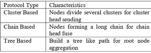
In general, WSNs can gather the sensed information by hundreds or even thousands of sensing nodes and transmit them to the sink. It uses the easiest way that sensor nodes transmit the sensed data to sink directly. Using this way is very simple, but it will have a serious problem. When a farther sensor node transmits the data, it will spend more energy than the closer one [1]. Therefore, it is desirable to make these nodes as energy-efficient as possible and to rely on their large numbers in order to obtain high quality results. Likewise, the sensor network routing protocols must be designed to achieve fault tolerance in the presence of individual node failures while also minimizing energy consumption. Moreover, since the limited wireless channel bandwidth must be shared by all the sensors in the network, routing protocols for these networks should be able to perform local collaborations in order to reduce the bandwidth requirements. Eventually, the data being sensed by the nodes in the network must be transmitted to a control center, that is, the sink or base station where the end sensor nodes can access the data. At present, there are many routing methods in the wireless sensor networks [26].The three primary types are discussed in Table 1[27]
Table I: Comparison of protocol type (Source: Chhabra and Sharma, 2011)
Protocol Type Characteristics
Cluster Based Nodes divide several clusters for cluster
head sending
Chain Based Nodes forming a long chain for chain
head fuse
Tree Based Build a tree like path for root node
aggregation
LEACH
Low-Energy Adaptive clustering Hierarchy (LEACH) protocol, is a representative of cluster-based routing protocol [18]. It is also the first proposed in wireless sensor network and can reduce power consumption on avoiding the communication directly between sink and sensor nodes [28]. In a sensor field, sensor node senses data and sends data to the sink called round [19]. The working procedure for LEACH finishes in a round. Before gathering the sensed data at each round, the huge number of sensor nodes are divided into several clusters and a cluster head chosen randomly by self-organization. Each cluster head is in charge of gathering the sensed data from the sensor nodes in the cluster. The cluster head will aggregate the received data and then send to the sink directly. After the sink receives all the data from cluster heads, a round will be ending. There are two phases in each round in LEACH [19]. These are setup phase and steady-state phase. The setup phase consists of two major steps: cluster formation and cluster head selection. Once the base station forms the primal clusters, they will not change much because all sensor nodes are immobile, whereas the selected cluster head in the same cluster may be different in each round. During the first round, the base station first splits the network into two sub clusters, and proceeds further by splitting the sub clusters into smaller clusters. The base station repeats the cluster splitting process until the desired number of clusters is attained [28]. When the splitting algorithm is completed, the base station will select a cluster head for each cluster according to the location information of the nodes. For a node to be a cluster head, it has to be located at the center of a cluster. Once a node is selected to be a cluster head, it broadcasts a message in the network and invites the other nodes to join its cluster. The other nodes will choose their own cluster heads and send join messages according to the power of the many received broadcast messages [29]. When the cluster head receives the join message from its neighbor node, it assigns the node a time slot to transmit data. When the first round is over and the primal cluster topology is formed, the base station is no longer responsible for selecting the cluster head [19]. The task of cluster formation is shifted from the base station to the sensor nodes. The decision to become a new cluster head is made locally within each cluster based on the node’s weight value [29].
PEGASIS
[image:4.595.46.293.681.768.2]children nodes, it will aggregate the data and transmit the collected data to sink directly.
TREEPSI
[image:5.595.305.539.326.695.2]A newer approach called a Tree-based Efficient Protocol for Sensor Information (TREEPSI) was proposed to handle some of the challenges of LEACH and PEGASIS [30]. TREEPSI is tree-based protocol that is different from the other protocols [30]. Before data transmission phase, WSNs will select a root node in all the sensor nodes. Set the root identify id=j. There are two ways to build the tree path. One is computing the path centrally by sink and broadcasting the path information to network. The other can be the same tree structure locally by using a common algorithm in each node [30]. At the initial phase, root will create data gathering process to the children nodes using any standard tree traversal algorithm. They go into the data transmission phase after building the tree. All the leaf nodes will start sending the sensed data towards their parent nodes. The parent nodes will collect the received data with their own data, then send the collected data to their parent. The transmission process will be repeated until all are received by the root node [20]. After the root node aggregates the data, it sends collected data to sink directly. The process will go around until the root node is dead. WSN will re-select a new root node. Root identification number would be j+1. Then the initial phase is performed again. The tree path will not change until the root node is dead. TREEPSI and PEGASIS are using the same way to transmit data from leaf node to chain/root head. The length of path form end leaf node to root/chain node in TREEPSI is shorter than PEGASIS. The data will not send data for a long path. For this reason, TREEPSI can reduce power consumption less in data transmission than PEGASIS [30]. The TREEPSSI has better performance about 30% than PEGASIS. It still has a problem of restriction on the binary tree algorithm, the path has made a detour in the topology [30]. In Table II, the scenario of the protocols was compared.
Table II: Comparison of Scenarios
D Proposed Approach
As seen in Table II, the energy efficiency in tree-based protocol like TREEPSI is better than cluster based and chain-based protocol. If some sensor nodes send data to the sink, this information of nodes will make a detour (Satapathy and Sarma, 2006). Thus, that will cause more power dissipation in data gathering. This situation happens
while building the binary tree paths, especially when the sensor field is large and the numbers of sensor nodes are large. In order to improve the reduction of power dissipation, a novel protocol was proposed to combine the cluster-based and tree-based protocol to improve performance (Heinzelman et al, 2000). A description of the deployment and method of the protocol is
1) Each node or sink has ability to transmit message to any other node and sink directly.
2) Each sensor node has radio power control node can tune the magnitude according to the transmission distance.
3) Each sensor node has the same initial power in WSNs. 4) Each sensor node has location information.
5) Every sensor nodes are fixed after they were deployed. 6) WSNs would not be maintained by humans.
7) Every sensor nodes have the same process
and communication ability in WSNs, and they play the same role.
8) Wireless sensor nodes are deployed densely and randomly in sensor field.
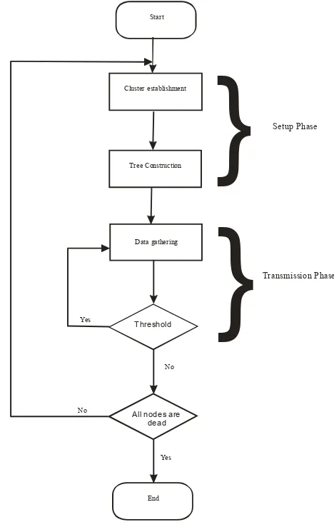
The proposed method flowchart is shown in Figure 2.
Tree Construction
Threshold
Start
All nodes are dead
Cluster establishment
Data gathering
No
Yes Yes
No
End
}
}
Setup Phase
[image:5.595.48.298.543.677.2]Transmission Phase
Figure 2: Proposed method flowchart
cluster head, has aggregated the data in the cluster, that is, when the round is formed, which means all root nodes have finished transmitting data [27].
Conclusion from the Cluster-Tree based approach
The new protocol was subjected to a detailed simulation of a wireless sensor network environment and it demonstrates that the method can reduce energy consumption, improve evenness of dissipated network energy and the ability of extending the life span of the network. The proposed method has several advantages in WSNs for data gathering. It reduces power consumption by avoiding direct communication between the sink and sensor nodes. The use of threshold mechanism, also increase the number of nodes alive and the network lifetime as compare to others. It protects the parent node from dying slowly because each node has chances to be parent. The clustered-tree based data gathering protocol works on two phases. With the help of the first phase, it maximized the network lifetime by balancing the energy consumption of the nodes and second phase reduced the communication overhead by forming tree structures [27]
Member Forward List Approach for Data Collection in Wireless Sensor Networks
Another reviewed proposal is the introduction of Member Forward List (MFL) for efficient approach in data collection for wireless sensor networks. This list includes the nodes with highest priority for forwarding the data. When a node fails or dies, this list is used to select the next node with higher priority [28]. The benefit of this node is that it prevents the algorithm from repeating when a node fails or dies. The results show that Member Forward List decreases power consumption and latency in wireless sensor networks.
A problem with chain-based structure happens when one neighbour fails and consequently the chain for that data transmission is lost. In cluster-based structure, the cluster head or aggregator node may be attacked by malicious attacker. The common issue with all of these structures is that when a forwarding node fails to transmit the received data to its neighbour or a node in a higher position, the whole structure is lost [28]. Consequently, the algorithm to construct the structure again needs to be repeated. This challenging point causes it to use more energy leading to latency in data forwarding. This paper proposes a tree-based algorithm for data forwarding to improve the stated common issue. This improvement is possible with the help of using a Member Forward List. This list helps the other nodes to find the route for data forwarding when a previous forwarder node has failed [31].
Design principle
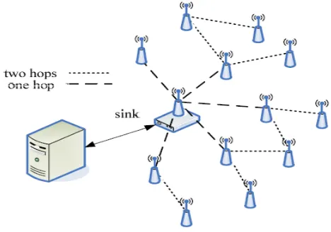
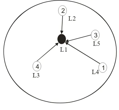
[image:6.595.312.546.56.220.2]The design principle of the proposed method for data collection in WSNs. illustrates the physical structure. There are two types of nodes in this network, the sink and the wireless sensor nodes [31]. The sink is responsible for informing the sensor nodes about the type of data needed and to gather the collected data from them. The sensor nodes gather the information from the environment and forward it to the other nodes which are closer to the sink from hop point of view. The physical model is shown in Figure 3.
Figure 3: Physical Model
In this approach, an efficient protocol was introduced to detect forwarder node for saving energy. In this protocol Member Forward List (MFL) was used to find an efficient and the shortest path for forwarding data to the sink. At the end, it was concluded that [28], MFL protocol decreases the latency, MFL protocol increases energy efficiency and it also prevents the algorithm from repeating when a node has failed or died for some reasons.
III. METHODOLOGY
The methodology used in this research is called Energy Efficient Priority Algorithm (EEPA). This is a hybrid method derived from a combination of LEACH [32] and Member Forward List [28]. This research studied the process of cluster head selection in LEACH and the proposed EEPA model. The two results were compared and the EEPA showed an improvement over the traditional LEACH method.
In the traditional LEACH method, at deployment the base station breaks the entire network down into clusters, then uses the node with the closest hop distance from it as the initial cluster head. This cluster head then advertises itself as the new cluster head and the base station hands the responsibility of cluster head selection over to the clusters. When a the cluster head dies and a new cluster head is to be selected, the algorithm is run severally by the sensor nodes
in the cluster to elect a new cluster head, which causes an
overhead and drains battery life.
The EEPA is used to group the sensor nodes in each cluster after the initial cluster head has been chosen to group the remaining sensor nodes into hierarchy of feasible cluster
head successors which is stored as a priority list file on the
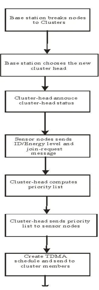
Figure 4: The EEPA algorithm
In a newly deployed wireless sensor network (WSN) environment, the base station (BS) breaks the WSN into various clusters, each cluster containing about 100 sensor nodes. The base station then selects a centrally placed node, which is not more than a hop away from it as the cluster-head. The new cluster head announces its cluster-head status. The sensor nodes send their identification (ID), which is their media access control (MAC) address, their corresponding energy level and join-request message. The cluster head then computes the priority list. The priority list is computed by considering the various energy levels and rates them accordingly. The one with the list energy level is rated from 1 to N. This is to ensure that the one with the highest energy level is chosen last as the cluster-head. This list is a succession list plan, which shows the order in which the nodes can act or serve as the cluster-head. The list is then sent to each sensor node, which is kept in their database. The list is also sent to each node along with their
TDMA schedule, which is the time allocated to each node within which they can send data to the cluster-head. This concludes the setup phase and the system moves to the steady phase in which it can monitor and detect changes depending on the parameter it is monitoring.
IV. DISCUSSION AND RESULT
[image:7.595.305.551.191.613.2]The existing LEACH algorithm is compared to the proposed Energy Efficient Priority Algorithm (EEPA) model using figures 5-10.
Figure 5: Node 5 as the cluster- head
Figure 6: Selection of node 3 as the new cluster-head
Figure 7: Selection of node 4
Figure 8: Selection of node 1 as the new cluster head as the new cluster head
2
Figure 9: Node 2 as the only remaining node that can be used as the cluster-head
The shaded dots or circles represent the current cluster-head.
2
3
1 4
2
3
1 4
2 1 4
[image:7.595.337.512.547.698.2]Figure 10: EEPA Model
Figure 5 to Figure 10 were used to illustrate the cluster-head selection process in the traditional LEACH algorithm. When the LEACH algorithm is run to elect the cluster-head each sensor node uses about 0.12 Joules of energy [33]; which is the amount of energy loss each time the algorithm is run. In this research, the number of sensor nodes is limited to 5, however, each cluster can support between 100 and 500 sensor nodes in practice. It is noted that in a cluster of 500 sensor nodes, the EEPA can have a minimum of 360 cluster-heads and a maximum of 480 cluster-head during the sensor nodes cluster life span.
Hence, each time the LEACH algorithm is run, 0.6J of energy is lost.
0.12 x 5J = 0.6J of energy is lost
Since the cluster-head selection process will need to be done 5 times, a total of
0.6J x 5 = 3J of energy will be lost
This continues for N number nodes in each cluster depending on the available number of nodes.
However, in Figure 10which depicts the EEPA model, when the cluster- head selection algorithm is run and the priority list is created.Assuming it takes twice the same energy
needed to run a traditional LEACH algorithm to run the
EEPA, each node uses:
about (0.12J x 2 = 0.24J) of energy for the process. A total of 0.24J x5 = 1.20J of energy is used. This translates to the total energy lost i.e 1.20J in the cluster
This looks high as compared to the initial 0.6J used to run the traditional LEACH algorithm. This is however a one-time occurrence and after the initial priority list has been created, there will be no need to run the traditional LEACH algorithm again.
At the initial setup, EEPA loses (1.2J – 0.6J = 0.6J) as compared to the initial setup of traditional LEACH But, on the long run the traditional LEACH loses (3J – 1.2J
= 1.8J) which is a significant loss
The proposed EEPA’s algorithm works as follows:
1. A selected cluster head broadcasts an advertised
message over neighbour nodes after being selected by the base station.
2. The sensor nodes send their identification, which is
their media access control address, their corresponding energy level and join-request message to the new cluster head.
3. The cluster-head computes the priority list by
considering the various energy levels and rates them accordingly.
4. The list is then sent to each sensor node, which is kept
in their database. The list is sent together with each sensor node’s TDMA schedule.
5. The member nodes receive and save the message.
[image:8.595.310.545.354.445.2]The EEPA model simply uses each node’s received, MAC address and energy levels to compute the priority list. In Figure 10, assuming each node submits its MAC address and energy level as stated in the Table III and 4:
Table III: ID and energy level given to the cluster-head
Nodes MAC Address Energy level
1 00-1E-10-1F-A6-B7 48J
2 00-1E-10-1A-A8-A7 44.78J
3 00-1E-10-1F-D6-B2 50J
4 00-1E-10-1F-C9-B7 45J
5 00-1E-10-1F-A6-AA 49J
Table IV: Priority/Cluster-head succession list
Nodes
PriorityList
MAC Address Energy level
2
L200-1E-10-1A-A8-A7
44.78J
4
L300-1E-10-1F-C9-B7 45J
1
L400-1E-10-1F-A6-B7 48J
3
L500-1E-10-1F-D6-B2 50J
Table III shows the original information sent to the initial cluster-head, which it uses by the aid of the EEPA model to create a priority list, showing how each node can act as a
successor node. This list is then sent to reach node in the
cluster, which is kept in their database for use in choosing the next cluster head.
2
3
1 4
L1 L2
L3 L4
V. CONCLUSION
It was shown that the EEPA model works better than the traditional LEACH method. The EEPA has a feasible succession plan in place that saves energy and time in the selection of a new cluster-head even though the initial overhead is a bit high. It also makes sure that the sensor node with the highest number of energy is the last on the list to make sure those nodes with lower energy also works as cluster-heads before they die. The priority list being kept by each of the nodes means they know in advance which nodes succeeds the current cluster-head and prepares for the task in advance.
REFERENCES
[1] Akyildiz I. F., W. Sankarasubramaniam Su, Y., and Cayirci E. (2002a) “Wireless sensor networks: A survey,” Computer Networks. Vol. 38, No. 4, pp. 393–422.
[2] Akyildiz, W. Su, Y. Sankarasubramaniam, and E. Cayirci (2002b), A survey on Sensor Networks, IEEE Communications Magazine. Vol. 40, Issue: 8, pp. 102. [3] Al-ObaisatYazeed and Braun Robin (2005). On Wireless
Sensor Networks: Architectures, Protocols, Applications,
and Management Institute of Information and
Communication Technologies University of Technology, Sydney, Australia. Pp 2-7.
[4] David Culler, Deborah Estrin and Mani Srivastava (2004). “Overview of Sensor Networks” IEEE Computer Society. Vol. 6, pp.6.
[5] NisbetAndy and Dobson Simon (2006). A systems architecture for sensor networks based on hardware/software co-design 1 Manchester Metropolitan University, Manchester UK, Department of Computer Science, University College, Dublin IE. Vol. 47, No. 6, pp3.
[6] Heinzelman W. R., Kulik J. and Balakrishnan H. (1999), “Adaptive Protocols for Information Dissemination in Wireless Sensor Networks,” In Proc. ACM MobiCom ’99, Seattle, WA. Vol.6, pp3
[7] Akkaya K. andYounis M., (2005), ”A Servey of Routing Protocols in Wireless Sensor Networks”, Elsevier Ad Hoc Network Journal. Vol .3, No3, pp325-349.
[8] Muruganathan S.D., Bhasin R.I., Fapojuwo A.O. (2005),”A Centralized Energy Efficient Routing Protocols for Wireless
Sensor Networks”, IEEE Radio Communication
Magazine.Vol. 4, pp.8-13.
[9] Stephane Lindsey, Cauligi S. Ragavendra and Krishna Sivalingam (2001),“ Data Gathering in Sensor Networks using Energy Delay Metrics”, Proceedings of the International Parallel & Distributed Processing Symposium. Vol. 4, pp.188
[10] BalamuruganP., DuraiswamyK. (2011), Chain Based Energy Proficient Gathering Protocol for Wireless Sensor Networks IJCST. Vol. 2, Issue 3, pp 2
[11] Indu Shukla (2006), Power Efficient Gathering in Sensor Information System (PEGASIS Protocol). pp3
[12] Stephanie Lindsey andCauligi S. Raghvendra (2005),
“PEGASIS: Power-Efficient Gathering in Sensor
Information System”. pp4.
[13] Sung-Min Jung, Young-Ju Han, Tai-Myoung Chung (2006), “The Concentric Clustering Scheme for Efficient Energy Consumption in the Pegasis”. Vol.2,No.2, pp 2.
[14] ManikandanK.andPurusothaman T. (2010). An Efficient Routing Protocol Design for Distributed Wireless Sensor Networks International Journal of Computer Applications (0975 – 8887). Vol. 10, No.4, pp5.
[15] Wendi Heinzelman, AnanthaChandrakasan, and
HariBalakrishnan (2000). Energy- Efficient Communication Protocol for Wireless Microsensor Networks. Proceedings of
the Hawaii International Conference on System Sciences, IEEE.Vol.10, No.4, pp 387.
[16] Yang Y., Wu H.-H., Chen H.-H. (2006), Short: Shortest hop routing tree for wireless sensor networks, in: Proceedings of IEEE ICC. Vol. 8, pp. 3450–3454.
[17] Khamforoosh K. and Khamforoush H. (2010), “A new rounting Algorithm for Energy Reduction in Wireless Sensor Networks”, IEEE.Vol.10,No.4, pp1472-1988
[18] Yun-Sheng Yen, Kai-Chun Huang, Han-Chieh Chao and Jong Hyuk Park. (2009), “Tree Clustered Data Gathering Protocol for Wireless Sensor Networks”, Journal of the Chinese Institute of Engineers. Vol.32,No.7, pp.1025-1036. [19] Heinzelman W., Chandrakasan A., and Balakrishnan H.
(2000), Energy-Efficient Communication Protocol for Wireless Microsensor Networks, Proc. Hawaii Conf. System Sciences. Vol.2, No.8,pp 584.
[20] Lindsey S., Raghavendra C. and Sivalingam K. M. (2002a), Data Gathering Algorithms in Sensor Networks Using Energy Metrics, IEEE Transactions On Parallel and Distributed Systems PEGASIS. Vol . 13, No. 9, pp8. [21] Lindsey S. and Raghavendra C. (2002b), Pegasis:
Power-Efficient gathering in sensor information systems In: Proc. of the IEEE Aerospace Conference. Vol. 2, pp.1-6.
[22] Lindsey S. and C.S. Raghavendra, (2002c) "PEGASIS: Power-Efficient Gathering in Sensor Information Systems,” Proceedings of IEEE on Conference Aerospace, Los Angeles, CA. Vol. 3, pp. 3-8.
[23] Min R., Bhardwaj M., Cho S., Sinha A., Shih E., Wang A. and Chandrakasan A. P. (2001), Low Power Wireless Sensor Networks Proceedings of International Conference, Bangalore, India.Vol.3, Issue-1, pp 26.
[24] Rabaey J. M., Ammer M. J., da Silva J. L. Jr., Patel D. and S. Roundy (2000), Pico Radio supports ad hoc ultra low power wireless networking, IEEE Computer. Vol. 33, pp. 42-48. [25] Sohrabi K., Gao J., Ailawadhi V. and G. Pottie (2000),
Protocols for Selforganization of a wireless sensor network, IEEE Personal Communications. Vol. 7, No. 5, pp. 16-27. [26] Jiang Q. and Manivannan D. (2004), ―Routing Protocols
for Sensor Networks, IEEE Consumer Communications and Networking Conference. Vol. 40, pp. 10.
[27] ChhabraGurpreet Singh and SharmaDipesh(2011), Cluster-Tree based Data Gathering in Wireless Sensor Network , International Journal of Soft Computing and Engineering (IJSCE) ISSN: 2231-2307. Vol.1, Issue-1, pp8.
[28] HaniehAlipour and AlirezaNemaney Pour (2007), An Efficient Data Collection Approach for Wireless Sensor Networks. Vol.8, pp 16.
[29] Maraiya K., Kant K. and N. Gupta (2002), "Architectural Based Data Aggregation Techniques in Wireless Sensor Network: A Comparative Study," International Journal on Computer Science and Engineering (IJCSE). Vol. 3, No. 3, pp.1131-1134.
[30] Satapathy S.S. and Sarma N. (2006), TREEPSI: tree based energy efficient protocol for sensor information,Wireless and Optical Communications Networks 2006, IFIP International Conference. Vol. 5, pp. 11-13.
[31] Zhang X. (2009), Data Collection in Wireless Sensor Networks, PhD thesis Electrical and Computer Engineering in the Graduate College of the University of Illinois at Chicago.Vol.8,No.4, pages 254-262.
[32] Chandrakasan A. and Sinha A. (2001). “Dynamic power management in wireless sensor networks,” Trans. Design and Test of Computers. Vol. 18, No. 2, pp. 62–74.