Abstract—The paper contains an analysis of different
approaches in numerical calculations of the joints of prefabricated elements in large-panel buildings located on the areas of mining damages using FEM programs for linear and non-linear models. Particular attention was devoted to the joints, which are the main cause of damage of these buildings. It is also essential to make proposals of how to strengthen these buildings due to the accidental loads resulting from foundations in the areas of mining damage.
Index Terms— FEM analysis, Joints, Large-panel buildings,
Mining areas
I. INTRODUCTION
The first buildings made using large-panel technology were built in Western Europe at the beginning of the fifties. The first building in Poland was built in 1957 on the Jelonki estate in Warsaw. The aim was to create cheap buildings that are quick to make and therefore available to everyone.
As a result, "Large-panel” technology was used on a large scale in the late 60's. However, the popularization of new built buildings was not accompanied with the required quality of technology, design solutions and execution.
The most common errors in the construction of large-panel buildings include the following:
-a too low reinforcement ratio of joints,
- a low concrete and mortar strength used for the creation of the joints,
- inaccurate filling of the joint using a concrete mix, - a lack of thermal insulation of the joints,
- a lack of controlling the material quality used on site, - improper execution of wall thermal insulation in the area of edges – not reaching the corner panel,
- non-compliance with regards to the verticality and concentricity of mounted elements.
Structural defects of the system and the quality of work are not the only factors that influence the durability and safety of a building. At that time, the problems related to the geological conditions were not taken into account. The aim of this paper is to present the problems concerning the
Manuscript received March 8, 2017; revised May 10, 2017.
J.Baranski and J. Szolomicki are with the Wroclaw University of Science and Technology, Wroclaw, POLAND (phone: +48 505-995-008; fax: +48 71-322-14-65; e-mail: jerzy.szolomicki@ pwr.edu.pl)
P. Latka wrote his master thesis at the Department of Civil Engineering, Wroclaw University of Science and Technology, Wroclaw, Poland.
foundations of large-panel buildings in the areas of mining damage. Particular attention was devoted to the joints, which are the main cause of damage of these systems.
This paper presents a numerical model of such a joint and analyses its behavior for different load combinations.
II. ANALYSISOFTHEIMPACTOFMININGDAMAGE ONLARGE-PANELBUILDINGS
The effects of mining exploitation can be divided into rock mass shocks and displacements. Rock mass shocks have an impact on buildings through ground vibrations. Mining exploitation causes the occurrence of rock bursts that are felt on the surface in the form of para-seismic shocks. These interactions can be defined by the following parameters: energy shock, vibration acceleration and vibration velocity. These parameters determine the harmful effects of vibration on buildings and their effect on people. The impact of shock can be determined by comparing the attributes of the existing scales of earthquake intensity: Richter, MSK and MCS. Movements of rock mass include a change of water conditions in the rock mass and surface and also continuous and discontinuous surface deformations of the area.
Continuous deformation is a deformation of the rock mass or subsurface layers as a result of mining exploitation. Deformation referred to as the subsidence basin is determined by the value of the so-called deformation ratios. The most commonly used deformation ratios in engineering practice are:
-w - vertical displacement, - T - inclination,
- K – curvature,
- R –radius of the curvature, - u - horizontal displacement, - ε- horizontal deformation.
Continuous deformations occur in the form of uneven depressions of an area. The values of the deformation ratios of the subsidence basin depend on the geological and mining conditions, including in particular:
- the thickness of the excavated backing layer, - the depth of the backing layer,
- the method of protecting the bottom of the excavated backing layer, which determines the rate of settlement, - the kind of load, which determines the range of the main influences β.
Numerical Analysis of the Joints
of Prefabricated Elements in Large-Panel
Buildings Located on the Areas of Mining
Damages
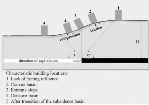
As a result of a theoretical shift of a building on the subsidence basin, five characteristic positions [1], which correspond to the extreme values of the deformation ratio (Figure 1), can be distinguished. The structure of a building is bent due to the curvature radius R in the case of building being located in the convex part of the subsidence basin. A normal tensile stress that causes vertical cracks generally occurs in the upper parts of walls. In the lower parts of the building, vertical cracks may occur and are caused by the loosening horizontal movement of mining, which induces tensile forces in the foundation. Diagonal cracks can also appear on the walls, which have a course of propagation rising from inside the building to the outer edge, depending on the direction of the principal stresses.
Figure 1 Scheme of transition of the subsidence basin under a building
The course of diagonal cracks rises towards the center of the building in the case of buildings located in the concave part of a subsidence basin. The curvature of the terrain has less of an effect on the overall deformations of the building and its shear deformation. Normal compressive stresses dominate in the walls that are subjected to the action of the periphery of the subsidence basin. In buildings with a rigid constructional scheme the occurrence of the effect of horizontal deformation of the mining area ε <0, which increases the existing pressure on the outer walls is possible. The simultaneous interaction of the horizontal deformations and curvature of the terrain occurring in the subsidence basin causes both bending and normal forces in the walls of the building located perpendicular to the mining exploitation. Normal and shear stresses are formed in the walls and their distribution along the height of the walls depends on the geometrical dimensions of the building structure and the relationship between internal forces.
Discontinuous deformation is defined as clearly noticeable distortion of the subsurface rock layers caused by mining exploitation. It can be divided into linear types of deformation such as faults, fractures, ground braces and also surface types of deformation, which include sinkholes, folds and landslides. Discontinuous deformations have the following characteristics:
- they are produced within a very short time,
- they appear in an impossible to determine time after the occurrence of the cause (voids in the rock mass),
- in most cases they cause complete destruction of the surface area above the deformation,
-they include local areas of small size, next to which there is almost no deformation.
During the occurrence of discontinuous deformation with a significant intensity, damage of a building’s construction can occur, which will lead to the loss of stability of parts or the whole structure. The most effective protection against discontinuous deformation is liquidation of their causes. In the case of no deep excavations, the causes can be eliminated through the backfilling or filling of voids in the rock mass.
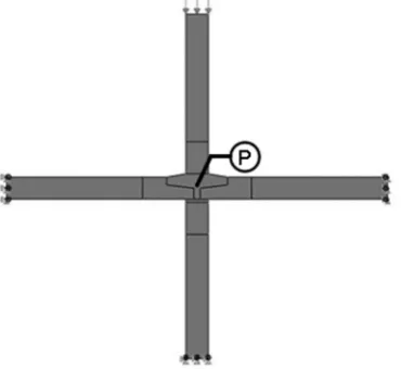
III. CHARACTERISTICSOFTHEWWPSYSTEM The WWP is a regional system of housing construction consisting of large-size elements. This solution was designed in 1968 and is characterized by a complex prefabrication and a high degree of work industrialization. Within the WWP system, buildings with 5 to 11 floors were built. These buildings had a transverse arrangement of load-bearing walls and a stiffening longitudinal inner wall that was usually located in the axis of the building. Floor slabs are based on two edges. Both the load-bearing and curtain external walls have three layers and are made of gravel concrete with styrofoam insulation. The floor plan of a typical building is shown in Figure 2.
Figure 2 A typical floor plan of a building constructed in the WWP system
[image:2.595.49.292.226.398.2] [image:2.595.308.550.382.462.2]fulfilled due to the quality of construction works. The cement mortar used on the contact of elements cannot be considered as a binder but only as a filling. These joints cannot be treated as monolithic because of the variety of materials, lack of continuous concreting and lack of connections with reinforcing bars. Instead, the joint should be taken as flexible, or in extreme cases of degradation, as pinned. During the analysis of joints in large-panel buildings, attention should be paid to the method of supporting the floor slabs. According to the assumptions of the system this support should be equal to 5cm. It is not enough, because the edges of the floor slabs and wall have no finish protecting them from damage. The low quality of construction works in conjunction with small displacements resulting from the settlement of the building or external forces (wind, vibration) can cause the floor slab to slip out from the ring beam.
IV. THECOMPUTERMODEL
In order to consider the influence of the connection state in the construction of a large-panel building on a load caused by the presence of mining damage a computer model of the joint was proposed. This model is a part of the structure corresponding to the geometrically typical horizontal joint of the WWP system. It includes elements such as prefabricated reinforced concrete floor slabs, wall panels, concrete filling and also cement mortar backing (Figure 3).
Figure 3 Computer model of a horizontal joint of the WWP system [2]
Numerical calculations were performed using the Abaqus 6.12-11 and Robot Structural Analysis Professional 2016 programs based on the finite element method (FEM). In order to accurately present the behavior of the structure of the building, a nonlinear model of concrete (conrete damaged plasticity) based on the models described by Lubliner [3] and by Lee & Fenves [4] was used.
In this model it is assumed that the two main failure mechanisms are tensile cracking and compressive crushing of the concrete material. The evolution of the yield or failure surface is controlled by two hardening variables , (plastic strains), related to failure mechanism under tension and compression loading, respectively.
Under uniaxial tension the stress-strain response follows a linear elastic relationship until the value of the failure stress, is reached. The failure stress corresponds to the onset of micro-cracking in the concrete material [6]. Beyond the
[image:3.595.316.546.92.261.2]failure stress the formation of micro-cracks is represented macroscopically with a softening the stress-strain response, which induces strain localization in the concrete structure.
Figure 4 Response of concrete to uniaxial loading in tension [5]
Under uniaxial compression the response is linear until the value of initial yield, of . In the plastic regime the response is typically characterized by stress hardening followed by strain softening beyond the ultimate stress, . It is assumed that the uniaxial stress-strain curves can be converted into stress versus plastic-strain curves. This conversion is performed automatically by Abaqus program after introduction of “inelastic” strain data. Tensile and compressive stresses can be presented in the following form:
̃ , ̃ , , , (1)
̃ , ̃ , , , (2)
[image:3.595.50.277.381.545.2]where subscripts t and c are respectively the tensile and compressive strength, ̃ and ̃ are the equivalent plastic strains, ̃ i ̃ are the equivalent plastic strain rates, is the temperature, and are other predefined field variables.
Figure 5 Response of concrete to uniaxial loading in compression [5]
As shown in Figure 5, when the concrete specimen is unloaded from any point on the strain softening branch of the stress-strain curves, the unloading response is weakened. The elastic stiffness of the concrete is reduced or degraded. The degradation of elastic stiffness is characterized by two damage variables and which are assumed to be functions of the plastic strains, temperature and field variables.
[image:3.595.310.551.495.640.2]̃ , , ; 0 1. (4) The damage variables can take values from zero, representing the undamaged material, to one, which represents total loss of strength.
If is the initial elastic stiffness of the material, the stress- strain relations under uniaxial tension and compression loading can be presented in the following form:
1 ̃ , (5)
1 ̃ . (6)
While the effective tensile and compressive stresses taking the following form:
!"# ̃ , (7)
$
!"#$ ̃ . (8)
The effective cohesion stresses determine the size of yield surface.
The joint in the analyzed model is uniformly loaded on the upper edge of the wall element. There is a fixed support at the free ends of the floor slabs and the lower wall panel (Figure 6). A point where the largest displacements occur during the increase of the load was selected as the characteristic point “P” of the joint. This point is in the middle of the analyzed joint. On the basis of the stress - strain at this point, it is possible to determine the substitute stiffness of the translation spring in the direction of the load according to the formula: % &'
('. Due to the complexity of
[image:4.595.108.533.48.353.2]the model shown in Figure 6, a simplified model of the joint is proposed. The upper wall element is connected to the rest of the structure by two elastic constraints for vertical kz and horizontal ky directions and one elastic rotating constraint kφ.
Figure 6 Load and boundary conditions of the joint
[image:4.595.52.237.447.617.2]The simplified substitute numerical model of the joint shown in Figure 7 allows the stiffness of joints to be changed from rigid connections (monolithic) to completely degraded ones (pinned). In this paper, simulations of changes in the stiffness of the joints was carried out, examining how it affects the behavior of the building structure under load. In the first phase, a 2D model of a 5-floor building was created, in which all horizontal joints were modeled as a 2D joint (Figure 8).
[image:4.595.312.550.507.610.2]Figure 7 Simplified substitute numerical model of the joint [2]
Figure 8 2D model of a 5-floor building
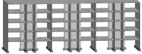
The load-bearing structures are beam elements with transformed geometric characteristics. In the second stage, a three-dimensional model was made of a 5-floor building in the WWP system (Figure 9). The load-bearing structure which was rigidly fixed to the substrate, was inserted into the model 3D joints, which are analogous to the 2D model were used as horizontal connections. The building was subjected to a dead load, wind and settlement of an external support, similar as in the two-dimensional model. For all load cases analysis of the displacements of construction was carried out for various parameters of the floor-wall joints.
Figure 9 3D model of a 5-floor building
wall panel. The relative displacements at point B are ∆x = 5mm and ∆z = 0,9 mm. In the case of ideal joints, the joints keep their rigidity and structural elements work together showing no displacement between themselves.
[image:5.595.309.552.475.555.2]Figure 10 Schematic load of a 5-floor building under an uneven settlement of supports
Figure 11 Schematic load of a 5-floor building under wind load
Another analyzed case load that influences a building was wind load applied perpendicular to the short side (Figure 11). The numerical FEM analysis found that, as in the case of the settlement of foundations, ideal joints are capable of transferring the internal forces (Table 1). These joints allow cooperation with all segments of the construction. As a result, the entire structural system carries the load evenly. For degraded joints, the wind effect is much more unfavorable for the building, Table 2. A large flexibility of joints makes the displacements of the structural system greater. Degraded joints have low stiffness in a horizontal direction, which affects the possible displacement of the gable wall panels.
TABLE 1COMPARISON OF DISPLACEMENTS OF A BUILDING IN COMPARATIVE POINTS A AND B UNDER SETTLEMENT FOR IDEAL AND DEGRADED JOINTS.
Settlement of outer segment of a building Displacement
point A (cm)
Displacement point B
(cm) x z x z Ideal -7,08 -0,71 1,35 0,00 joint
Degraded joint
-7,34 -1,86 1,45 0,00
TABLE 2COMPARISON OF DISPLACEMENTS OF A BUILDING IN COMPARATIVE POINT A UNDER WIND LOAD FOR IDEAL AND DEGRADED JOINTS.
Wind load Displacement
point A (cm) x z Ideal 1,86 -0,07 joint
Degraded 2,52 -0,10 joint
V. STRENGTHENINGOFTHEBUILDINGDUETO THEDEGRADATIONOFTHEHORIZONTALJOINTS
INTHELOAD-BEARINGSTRUCTURE
[image:5.595.39.289.547.645.2]In the following analysis, the authors numerically verified the strengthening of a building with degraded horizontal joints in its structure that were caused by mining tremors. This reinforcement was based on the thickening of the longitudinal walls to 15 cm and making a continuous reinforcement throughout the height of the entire building. This would form a monolithic cores. In addition, the floor on the top storey was thickened by 8 cm by executing an additional reinforced concrete slab. This procedure was carried out to increase the shear rigidity of the building by better joining together the monolithic cores. Thickening of the floors above the remaining storeys is not possible due to the change in the free height of rooms. Additionally, the external reinforced concrete or steel-concrete columns were combined along the entire height of the building with transverse walls and foundations and were also tied with braces on the top floor. This reinforcement increases the rigidity of the structure in a perpendicular direction to the long side of the building. The proposed strengthening and model of a degraded joint was implemented in the computer model. The model of the reinforcement, in the form of thickened longitudinal walls and a thickened floor on the top storey, has not brought about the expected results. The displacement of the characteristic points during the settlement of supports and the impact of the wind did not differ from the displacement obtained for the degraded joints in the model that was not reinforced. This is due to the fact that the structure has only three transverse walls with length of 2.4m. It was therefore decided to extend the wall as shown in Figures 12 and 13.
Figure 12 Floor plan of a building constructed in the WWP system that was subjected to strengthening
Figure 13 Scheme of a 5-floor building that was subjected to strengthening by extending the transverse walls
[image:5.595.308.545.588.679.2] [image:5.595.40.286.674.772.2]strengthened model, the maximum horizontal displacement was decreased by 57% under the settlement of supports and by 76% for the wind effect. Vertical displacements have a negligible value after strengthening of the construction.
TABLE 3COMPARISON OF DISPLACEMENTS OF A BUILDING IN COMPARATIVE POINTS A AND B UNDER SETTLEMENT FOR DEGRADED JOINTS WITH AND
WITHOUT STRENGTHENING. Settlement of outer segment of a building
Displacement point A
(cm)
Displacement point B (cm) x z x z Degraded -7,34 -1,86 -1,45 0,00 joint
Degraded -3,16 -0,10 -0,10 0,00 joint with
strengthening
Change (%) 56,95 94,62 93,10 - TABLE 4COMPARISON OF DISPLACEMENTS OF A BUILDING IN COMPARATIVE
POINT A UNDER WIND LOAD FOR DEGRADED JOINTS WITH AND WITHOUT STRENGTHENING.
Wind load Displacement
point A (cm) x z
Degraded 2,85 -0,12 joint
Degraded 0,67 -0,01 joint with
strengthening
Change (%) 76,49 91,67
VI. CONCLUSIONS
On the basis of the analysis of the computer models of the large-panel building, it can be concluded that the state of horizontal joints has a large influence on the selection of the static scheme of a construction, its stability and also its behavior under the influence of external loads. The main reason for the poor condition of the joints is the lack of proper reinforcement, which would carry the tensile forces generated by the settlement of foundations and wind actions. As shown by numerical analysis, the structure with the degraded joints is less resistant to external impact. The stiffness of the building is smaller and is subject to greater displacements than the ideal joint case. In the case of accidental loads, which are the loads from the influence of mining (uneven settlement of buildings, para-seismic shocks) there is a high probability of failure in buildings made of large-panel technology.
REFERENCES
[1] L. Fedorowicz, J. Fedorowicz, “Relationship building-mining exploition. Techniques for creating a numerical model (written in Polish), Inżynier budownictwa, no. 4, pp. 113-119, 2014.
[2] P. Latka, “Influence of the joints of prefabricated elements on the limit states of large-panel buildings located on the areas of mining damages” (written in Polish), Thesis, Department of Civil Engineering, Wroclaw University of Science and Technology, 2016, Poland.
[3] J. Lubliner, J. Oliver, S. Oller and E. Onate, “A Plastic-Damage Model for Concrete”, International Journal of Solids and Structures,
vol. 25, pp. 299-329, 1989.
[4] J. Lee, G. L. Fenves, “Plastic-Damage Model for Cyclic Loading of Concrete Structures”, Journal of Engineering Mechanics, vol. 124, no. 8, pp. 892-900, 1998.
[5] Abaqus 6.12, Abaqus Analysis User’s Manual, SIMULA, 2012. [6] A. Hillerborg, M. Modeer and P. E. Petersson, “Analysis of Crack
![Figure 3 Computer model of a horizontal joint of the WWP system [2]](https://thumb-us.123doks.com/thumbv2/123dok_us/413942.538947/3.595.50.277.381.545/figure-computer-model-horizontal-joint-wwp.webp)