8080/8085
The following are differences between Microtec's Assembler and the Intel Assembler described in Intel's 8080/8085 Assembly Language Programming Manual #98-30lA.
- Microtec allows EBCDIC characters to be specified
- No limit to number of operands for DB or DW directives - Only operators allowed are +,-,*,/,.LOW.,.HIGH.
- Expressions may c~ntain no blanks. In particular the HIGH and LOW operators are delimited by periods.
- An instruction may not appear as an operand, e.g. (MOV A,B) - Colons are not needed to terminate a label which starts
in column one.
- Comments may begin with asterisks or semicolons
- The comment field on a statement need not start with a semicolon
- The following directives are not supported REPT
IRP IRPC
.- The following characters do not have any special meaning as Macro Operators
..
,
,
NUL%
TABLE OF CONTENTS
1.0 INTRODUCTION 1-1
2.0 ASSEMBLER LANGUAGE 2-1
Statements 2-2
Comment Statement 2-3
Reserved Symbols 2-3
Symbolic Addressing 2-4
Assembly Program Counter 2-6
3.0 SYNTAX 3-1
Character Set 3-1
Symbols 3-2
Constants 3-3
Expressions 3-5
Special Arithmetic Operators 3-5
4.0 DIRECTIVES 4-1
'ORG 4-3
END 4-4
EQU 4-5
SET 4-6
DB 4-7
DATA 4-7
DW 4-8
ACON 4-8
DDB 4-9
DS 4-10
EJEC 4-11
SPAC· 4-12
TITLE 4-13
LIST 4-14
NLIST 4-15
IF 4-16
ELSE 4-17
ENDIF 4-18
6.0 RELOCATION
Relocatable Symbols Relocatable Expressions Relocation Directives ASEG CSEG DSEG ORG PUBLIC EXTRN NAME STKLN
7.0 HOW TO USE THE ASSEMBLER The Assembler
Assembler Operation Assembler Listing The Object Module
Cross Reference Format
APPENDIX A - Assembler Error Codes APPENDIX B - ASCII and EBCDIC Codes APPENDIX C 8080/8085 Operation Codes APPENDIX D - Hexadecimal Notation
APPENDIX ~ - Hexadecimal-Decimal Conversion Tables
INTRODUCTION
Microtec has developed a Relocatable Macro Assembler for the 8080/8085 microprocessor.that translates Symbolic Machine Code into relocatable object code which may then be processed by Microtec's Linking Loader. The Assembler program is written in FORTRAN IV to achieve compatibility with most computer·
systems. It is modular and may be executed in an overlay mode should memory restrictions make that necessary. The program is approximately 3800 FORTRAN statements in length, 20% of which are comments. The program is written in ANSI standard FORTRAN IV and no facility peculiar to anyone machine was utilized. This was done in order to eliminate FORTRAN compatibility problems.
The mnemonic Operation Codes as well as Directives are identical to those utilized by Intel in their literature and in their software products. This has been done to eliminate any possible problems of program compatibility and to obviate the necessity of learning new assembly languages.
The assembler is a two pass program that builds a symbol table, issues helpful error messages, produces an easily read program listing and symbol table, and outputs a computer
readable relocatable object (load) module.
These features aid the programmer/engineer in producing
well documented, working programs in a minimum of time.
Additionally, the assembler is capable of generating data in
several number based systems as well as both ASCII and EBCDIC
character codes.
MicrQtec does not present any information in this manual
that will help the user understand the 8080 or 8085
micr6-processor, nor has any information been included to help the
user write working programs. The reader is referred to the
ASSEMBLER LANGUAGE
The assembler language provides a means to create a
computer program. The features of the Assembler are designed to meet the following goals:
• Programs should be easy to create • Programs should be easy to modify
• Programs should be easy to read and understand • A machine readable load module to be generated
This assembler language has been developed with the following features:
• Symbolic machine operation codes (opcodes, mnemonics) • Symbolic address assignments and reference
• Relative addressing
•. Data Creation statements
• Storage reservation statements
• Assembly listing control statements • Addresses may be generated as constanbs
• Character codes may be specified as ASCII or EBCDIC • Comments and remarks may be ericoded for documentation • Cross reference table listing
• Relocatable object format
The symbolic machine instruction is a written specification for a particular machine operation expressed by symbolic
operation codes and sometimes symbolic addresses or operands. Example:
ISAM MOV A,M
where:
ISAM - is a symbol which will represent the memory address of this instruction.
MOV - is a symbolic opcode which represents the bit pattern of the "move" instruction.
A - is a symbol, in this case a reserved symbol
representing the bit pattern for the accumulator.
M - is a symbol, another reserved symbol, representing memory accessed through registers Hand L.
A directive statement is a statement which is not translated into a machine instruction, but rather is interpreted as a directive to the assembler program. Example:
ABAT DW DELT
where:
ABAT - is a symbol. The assembler is to assign the memory address of the first byte of t~e two
allocated bytes to this symbol.
DW - is a directive which directS· the. assembler program to allocate two bytes of memory.
Statements
Statements are always written in a particular format. This format is depicted below.
LABEL FIELD OPERATION FIELD OPERAND FIELD COMMENT FIELD
The statement is always assumed to be written on an 80 column data processing card or as an 80 column card image.
The Label Field is provided to assign symbolic names to bytes of memory. If present, the label field may begin in any column if it is terminated by a ~olon. It may also begin in column one and not be terminated by a colon. A label may be the only field on the statement.
The Operation Field is provided to specify a symbolic operation code, a directive, or a macro call. If present this
field must either begiri past column one or be separated from the Label Field by one or more blanks or a colon.
The Operand Field is provided to specify arguments for the operation in the Operation Field. The Operand Field, if present, is separated from the Operation Field by one or more blanks.
Comment Statement
A Comment statement is a statement that is not processed by the assembler program. It is merely reproduced on the
assembly listing. A comment statement is indicated by encoding an asterisk or a semicolon as the first non-blank character~
I
Example:
·r
THIS IS A COMMENT STATEMENTLogical columns 73-80 are never processed by the assembler. This field is'a good place for sequence numbers, if desired.
Reserved Symbols
This assembler has internally defined twelve symbols. They are the register and segment names that Intel uses in their
product descriptions. These symbols have been defined to save the user the trouble of defining them in each program.
Although these symbols need not be used, they typically are used very frequently.
The user may assume the following statements have been included at the beginning of each assembled program but they will not appear on the program listing:
A EQU 7 H EQU 4
B EQU
0
L EQU 5C EQU 1 M EQU 6
The values to which these labels have been assigned are the
Intel codes for the source or the destination of the
micro-processor instructions.
These reserved labels may not be used in the label field.
to do so will generate an error flag.
Symbolic Addressing
When writing statements in symbolic machine language, i.e.
assembler language, the machine operation code is usually
expressed symbolically. For example, the machine instruction ,
that moves data from register B into the memory location
addressed by the contents of register pair H,L may be expressed
as:
MOV M,B
When translating this symbolic operation code and its
arguments into machine language for the 8080, the assembler defines one byte containing 70H (112) at the memory location in the current Assembly Program Counter. The address of the
translated byte is known because the Assembly Program Counter
is always set to hold the address of the byte currently being
assembled.
The user can optionally attach a label to such an
instruction. For example:
SAVE MOV M,B
would be made equivalent to the value 127 for the duration of the assembly.
The symbol could then be used anywhere in the source program to refer to the location of the instruction. The important concept is that the address of the instruction need not be known; only the symbol need be used to refer to the
instruction location. Thus when jumping to the MOV instruction the user could write:
JMP SAVE
When the "jump" instruction is translated by the assembler, the address of the MOV instruction is placed in::the address
field of the JMP instruction.
It is also possible to use symbolic addresses which are near other locations to refer to those locations without defining new labels. This may be done through use of the
+
and - operators. For example:BEG
JMP BEG JPE
MOV HLT
BEG+4 A,B
MVI C, 'B' INR B
Assembly Program Counter
During the assembly process the assembler maintains a
FORTRAN word that always contains the address of the next
memory location to be assembled. This word is called the
Assembly Program Counter. It is us~d by the assembler to
a,s s i g n add res s e s t 0 ass e m b 1 e d by t e s, but i t i s a l s 0 a va i
l'
a b 1 eto the programmer.
The character "$" is the symbolic name of the Program
Counter. It may be used like any other symbol, but i t may
not appear in the label field.
When using the "$", the programmer may think of i t as
expressing the idea; "$"
=
"address of myself." For example:10 JMP $
The jump instruction is in location 10. The instruction
directs the microprocessor to "jump to myself." The Program
Counter in this example contains the value 10 and the
instruction will be trans1at;ed to a "JMP 10." This could
SYNTAX
The Assembler Language is a language like any other. That is, it has a character set, vocabulary, rules of grammer, and allows for individuals to define new words or elements. The rules that describe the language are termed the syntax of the language.
For an expression or statement in assembler language to be translated by the assembly program it must be written correctly in accord with the rules of syntax.
Character Set
The following list of characters are the only ones that the assembler will recognize. Use of any other characters will cause the assembler to generate an error message.
Alphabetic Characters
ABC D E F G H I J K L M N 0 P
Q
R STU V W X Y Z~ blank character
Numeric Characters
o
1 2 3 4 5 6 789Special Characters
& ampersand colon
exclamation semi-colon
"
double quote'=
equal signII sharp sign ? question mark
% percent
Symbols
A symbol is a sequence of characters. The first character
in a symbol must be alphabetic or the special characters ? or
@. Special characters except for the above two may not be
used in a symbol. Imbedded blanks are not permitted. The
user is cautioned not to use symbols that start with the ?
character as the assembler generates "local" symbols starting
with this character.
Only the first six characters of a symb~l are used by the Assembler to define that symbol; the remaining characters
are for documentation. The parameter that dictates the number
of characters used to define a symbol may be changed in the
Fortran Source code.
The Assembler's symbol t~ble can contain up to 200 symbols.
If more symbols are requred, the symbol table may be increased
in size by changing a parameter in the Fortran Source code.
Symbols are used to represent arithmetic values, memory
,Examples of invalid symbols:
Constants
ABORT* lLAR PAN N
(contains special character) (begins with a numeric)
(embedded blank. symbol is PAN)
A constant is an invariant quantity. It may be an arith-metic value or a character code. There are several ways of specifying constants in this assembler language.
Decimal constants may be defined as a sequence of numeric characters optionally preceded by a plus sign or a minus sign. If unsigned, the value is assumed to be positive.
In most cases constants must be contained in one or two bytes. A one byte constant can contain an unsigned number with a value from
0
to 255. A two byte unsigned constant can range from0
to 65535. When a constant is negative isequivalent two's complement representation is generated and placed in the field specified. A one byte two's complement negative number can range from -1 to -256. A two byte two's complement number may range from -1 to -65536.
All constants are evaluated as 16 bit quantities, i.e. modulo 65536. Whenever an attempt is made to place a constant in a field for which i t is too large, an error message is
B - binary
o
octalQ -
octal D - decimalH - hexadecimal
Examples of these constants are:
l00llB 25 0FFH 37Q 255D 13570
As ASCII or EBCDIC character constant may be specified
by enclosing a single character within quote marks and preceding
i t with an A for ASCII ro an E for EBCDIC. If no descriptor
is specified the string is assumed to be ASCII. Examples of
this constant form are:
MVI A, ' 1 '
MVI C,E'A'
ORI '0'
A character string may be specified by using the DB or
DATA directive. Character strings must follow the format
described for these directives (see Section 4). Character
strings may be specified as ASCII or EBCDIC in a similar
manner as the character constant.
string are:
A'TELETYPE CODES'
E'TERMINAL CODES'
123.8'
To cause the code for a single quotation mark to be generated in the character constant or string i t must be specified as two single quote marks. Example:
'DON' 'T '
The character ~ode for a single quotation mark will be generated once for every two marks that appear contiguously within the character string.
Expressions
An express ion is a .sequence 0 f one or more symbols,
constants, or other expressions separated by the arithmetic operators·+,-~*,/ and the special arithmetic operatdrs
discussed later. Parenthesis are used in the normal manner to establish the correct order of the arithmetic operators. Expressions are evaluated left to right with multiplication and division being performed before addition and subtraction.
The expression must resolve to a single unique value.
Consequently character strings are not permitted in expressions. All expressions are evaluated modulo 65536 and hence are all 16 bit quanti'ies. In most cases the value of the final expression must be contained in either one or two bytes. If an attempt is made to place an expression in an one byte field and the expression is too large, an error message is generated. Examples of expressions:
PAM+3
than, have been assigned as special arithmetic operators. They correspond to the Intel operators .LOW. and .HIGH. and are
used to perform the following operations:
.LOW. or > - take low 8 bits of expression .HIGH. or < - take high 8 bits of expression
These special operators are unary and may be used anywhere in an expression. They have precedence over all other operators, e.g. >A+B*C is not the same as >(A+B*C). Example:
>IASM <IASM
.LOW.E1+S
These operators have been provided to help the user define two byte addresses as individual bytes whenever that is desirable. The result of application of either of these operators is a one byte value.
The following example demonstrates the utility of these operators.
LXI H,BUFF LOOP MOV A,M
CPI 13
JZ MAIN
INX H
DIRECTIVES
. The directives or pseudo-operat'ions are written as ordinary statements in the assembler language, but rather than being
translated into equivalent machine language they are interpreted as directives to the Assembler itself.
Through use of these directives, the Assembler will reserve memory space, define bytes of data, control the listings, assign values to symbols, etc.
This section describes all directives except those
primarily associated with macro assembly and relocation although some directives such as ORG apply to both absolute assembly
and relocatable assembly.
The directives described in this section are:
ORG END
EQU
SET DB· DATA DW ACON DDB DS
Set Program Origin End of Assembly
Equate a Symbol to an Expression Equate a Symbol to an Expression Data Definition
Data Definition (same as DB) Define Word '
Address Constant (same as DW) Define Double Byte
ELSE ENDIF
Conditional Assembly Statement Converse End Conditional Assembly code
ORG Set Program Origin (non relocatable mode)
The ORG directive is used to inform the assembler of :the memory address to which the next assembled byte should be assigned. All subsequent bytes will be assigned sequential addresses beginning with this address.
If the program does not have an ORG as the first statement, an ORG
0
is assumed and assembly will begin at location zero with absolute assembly.Example:
ORG
100H
(
{label} ORG expressionwhere~
label - is an optional label which if present will be equated to the given expression.
END-_ End of Assembly
The END directive is used to inform the assembler that the last card of the source program has been read, as well as indicate the load module starting address. Any statements following the END directive will not be processed.
Example:
END MAIN
r
END {expression}where:
expression - is an address that is placed in the
The EQU directive is used to ~ause the assembler to assign a particular value to a new label. This value may be an
absolute value or be a relocatable segment value (see Section 6).
Example:
SEVEN EQU 7
r
label EQU expressionwhere:
label - is a symbol defined by this statement expression - is an expression whose value will be
assigned to the given label for the duration of the current ~ssembly. An
SET Equate a Symbol to an Expression
The SET directive may be used to set a symb6l equal to a particular value. Unlike the EQU directive, ~ulitple SET directives for the same symbol may be placed in the same source program. The most recent SET directive determines the value of the symbol at any given place in the source program.
Example:
(
label SETGO GO
SET SET
expression 5 GO+lO
where:
label - is a symbol defined by this statement expression - is a value that will be assigned to the
given label until changed by another SET directive. Any symbols used in the
DB DATA
Data
Definition-The DB and DATA directives are used to define up to 70 bytes of data. The assembler will allocate one byte if an expression is given and will allocate several bytes if a character string is given. All expressions must evaluate to an one byte value or an error is generated. Negative values are stored using their two's complement representation. If an operand is a relocatable expression, it must be preceded by the .LOW. or .HIGH. operators. If neither operator is
present an error is generated and the .LOW. operator is assumed.
Example:
{label}
where: label
DB
DATA
ITEM
OUT2
DB DATA DB
+122,17,.LOW.EXPl 6,.1 FH, 'A'
+
1, 32 QA'ERR 1',7
- is an optional label which will be assigned the address of the first byte defin~d.
operandi - is an evaluatable expression contained in one byte, a character constant or an ASCII or
. ~
DW
AeON
Define Word
The DW or
AeON
directive informs the assembler to allocate two bytes per operand. Each operand is stored in successivebytes. The operands are stored with the low order 8 bits in
the first byte and the high order 8 bits in the second byte.
Negative values are stored using their two's complement
representation.
Example:
{label}
where:
DW
AeON
ADDl DW
AeON
lBH,40 1000,10000
operand
l , {operand2},
label - is an optional label which will be assigned
the address of the first byte defined.
operandi - is an evaluatable expression contained in
two bytes. A total of 70 bytes may be
DDB Define Double Byte
This directive is similar to the DW directive except for the order in which the 16 bit value of each operand is stored. The low order 8 bits of the operand are stored in the second byte of the double byte and the high order 8 bits are stored in the first byte. Negative values are stored using their two's complement representation.
Example:
REVl DDB 1000,10000
(
{label} DDB where:- is an optional label which will be assigned the address of the first byte defined.
operand. - is an evaluatable expression contained in
1
label
DS Define Storage
The DS directive is used to reserve a block of sequenti~l
bytes of storage. This directive merely cause the program
counter t6 be advanced. Therefore, the contents of the reserved bytes are unpredicatable.
Example:
PAT DS 62H
(
{label} DS expressionwhere:
label - is an optional label which will be assigned the address of the' first byte allocated. expression - a value which specifies the number of bytes
to be allocated by this directive. Any symbols used in this expression must be previously
EJEC Advance Listing Form to next Page
This directive instructs the assembler to skip to the
top of' the next page on the listing form. Its purpose is to
make program listings' easier to read.
to start each subroutine on a new page.
will not appear on the listing.
(
EJECSome programmers prefer
SPAC Space lines on listing
The SPAC directive causes one or more blank lines to appear on the output listing. It enables the programmer to format
the program listings for easier reading. The directive itself does not appear on the listing.
Example:
SPAC 7
(
SPAC expressionwhere:
TITLE Set Program Heading
. The TITLE directive is used to print a heading at the
beginning of each page of the listing. The default heading
defined by the assembler and used if the programmer does not
specify one via this directive is: "8080/8085 ASSEMBLER VER
. MR". For a user specified t i t l e to appear on the first
page of the output listing, the TITLE directive must be the
first statement in the program.
"
Example:
TITLE 'TEST PROGRAM'
(
TITLE 'heading'where:
heading - t i t l e which will be placed at the beginning
of each page. The heading may be up to 50
characters, with any additional characters
not appearing in the title. The heading is
delimited' by single quotes but if the
terminating quote is not present the first 50
characters will be used as the t i t l e . Heading
may contain no characters in which case the t i t l e
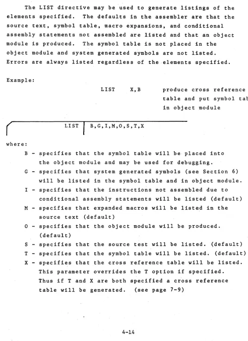
LIST List the Elements Specified
The LIST directive may be used to generate listings of the
elements specified. The defaults in the assembler are that the
source text, symbol table, macro expansions, and conditional
assembly statements not assembled are listed and that an object
module is produced. The symbol table is not placed in the
object module and system generated symbols are not listed.
Errors are always listed regardless of the elements specified.
Example:
(
LISTLIST X,B
B,G,I,M,O,S,T,X
produce cross reference
table and put symbol table
in object module
where:
B - specifies that the symbol table will be· placed into
the object module and may be used for debugging.
G - specifies that system generated symbols (see Section 6)
will be listed in the symbol table and in object module.
I - specifies that the instructions not assembled due to
conditional assembly statements will be listed (default)
M - specifies that expanded macros will be listed in the
source text (default)
[image:33.615.78.571.87.765.2] [image:33.615.78.579.234.766.2]NLIST Suppress Listing of the Elements Specified
The NLIST directive instructs the assembler to suppress
the listings of the elements specified. The listings may be
enabled again by the LIST directive. Errors generated by the
assembler are always listed regardless of the l i s t flags. Thus
to obtain an output listing of only errors the user should
specify "NLIST SIt at the beginning of the program.
Example:
NLIST
°
(
NLIST B,G,I,M,O,S,T,Xdo not produce an
object module
where:
B - specifies that the symbol table will not be placed
into the object module.,
G - specifies that system generated symbols will not be
listed in the symbol table or object module.
I - specifies that th~ instructions not assembled due to
conditional assembly statements not be listed.
M - specifies that expanded macros not be listed.
° -
specifies that the object module will not be produced. S - specifies that the source text will not listed. Onlythose statements with errors will be listed.
IF Conditional Assembly Statement
The IF directive may be used to conditionally assemble
source text between the IF directive and the ELSE or ENDIF
directive. If the expression in the operand field is
evaluated to any non-zero value, the code will be assembled.
If the expression evaluates to a value of zero the code will
not be assembled. IF statements may be nested up to 16 levels
an.d app'ear in the source text at any place.
Example:
IF SYSTEM
(
IF expressionwhere:
expression - evalutes to a value which determines whether
or not the assembly between the IF and following
ELSE or ENDIF will take place. Any symbols
used in this expression must be previously
defined. The expression may not be
ELSE Conditio~al Assembly Statement Converse
The ELSE directive is used in conjuction with the IF directive and is the converse of the IF. If the expression of the IF directive was zerot all statements between the ELSE
directive and the next ENDIF are assembled. If the expression of the IF directive was non-zero, all statements between the ELSE directive and the next ENDIF are not assembled.
The ELSE directive is optional and can only appear once within in IF-ENDIF block.
Example:
IF MAIN
ELSE
ENDIF
ENDIF End Conditional Assembly Code
The ENDIF directive is used to inform the assembler where
the source code subject to the conditional assembly statement.
ends. In the case of nexted IF statements, an ENDIF is paired
with the most recent IF statement.
Example:
In the following code, if the expression SUM-4 is equal to
zero, the instructions between the IF and ELSE directives will
not be assembled and those between the ELSE and ENDIF will be
assembled. If SUM-4 is non-zero the opposite occurs. To not
l i s t the non assembled instructions the "NLIST I" directive
may be used.
EI
IF SUM-4
assembled if SUM-4 ORI 0FAH
is non-zero ADC B
ELSE
assembled if SUM-4 ORI 07FH
is zero ADD C
ENDIF
MACROS
A macro is a.sequence of instructions that can be inserted
in the assembly source text by encoding a single instruction, the
macro call. The macro definition is written only once and can
be called any number of times. The macro definition may contain
parameters which can be changed for each call. The macro facility
simplifies the coding of programs, reduces the chance of programmer
error, and makes programs easier to understand as the source
code need only be changed in one location, the macro definition.
A macro definition consists of three parts; a heading,
a body, and a terminator. This definition must precede any
macro call. A macro may be redefined at any time with the
latest definition of a macro name applying to a macro call.
A standard assembler mnemonic (e.g. ·LXI) may also be redefined
by defining a macro with the name LXI. In this case all
subsequent uses of the LXI instruction in the program will
cause the macro to be expanded.
Macro Heading
The heading, which consists of the directive MACRO, gives
the macro a name and defines any formal parameters for the macro.
If a macro name if identical to a machine instruction or an, assembler directive, the mnemonic is redefined as the macro. Once a mnemonic has been redefined as a macro, there is no way of returning that name to be a standa~d mnemonic. A macro name may also be redefined as a new macro with a new body.
The operand field of the MACRO line contains the name of dummy formal parameters in the order in which they occur on the macro call. Each parameter is a symbol and multiple parameters must be separated by comments. The scope of a formal parameter is limited to its specific macro definition.
Macro Body
The firs't line of code following the MACRO directive
which is not a LOCAL directive is the start of the macro body. These statements are placed in a macro file for use when the macro is called. At expansion time, an error will be generated if another macro is defined within a macro. No statements are assembled at definition time including the Assembler directives.
r
{label} ENDMwhere:
label - is an optional symbol which becomes the symbolic address of the first byte of memory following the inserted macro.
Macro Call
A macro may be called by encoding the macro name in the operation field of the statement. The format of the macro call is shown below.
(
{label} name parameter listwhere:
label - is an optional label which will be assigned a value equal to the address of the first
instruction in the macro.
name - is the name of the macro called. This name should be defined by the MACRO directive or an error message will be generated.
parameter - is a list of parameters separated by commas. list These parameters may be constants, expressions.
, ,The parameters in the macro call are actual parameters and
their names may be different than the formal parameters used in
the macro definition. The actual parameters will be substituted
for the formal parameters in the order in which they are written.
Commas may be used to reserve a parameter position. In this case
the parameter will be null. Any parameters not specified will
also be null. The parameter l i s t is terminated by a blank or
a semicolon.
All actual parameters are passed as character strings into
the macro definition statements. Thus symbols are passed by
name and not by value. In other words the parameters are not
evaluated until the macro expansion is produced. Thus SET
directives within a macro may alter the value of parameters
passed to the macro.
During the macro expansion, the assembler recognizes
certain characters to have special meaning. The ampersand
"&", is used to concatenate the text of the definition line
and any actual parameters. During macro expansion, an ampersand
immediately preceding or immediately following a formal parameter
is removed and the substitution of the actual parameter occurs
at that point. If the ampersand is not immediately adjacent
to the parameter, the ampersand is not removed and remains
part of'the definition line. Ampersands within character
within nested macro calls. The brackets are the only way to
pass a parameter that contains a blank, comma or other delimiter. F'or example to use the instruction "LXI H,0" as an actual
parameter, would require placing <LXI H,0> in the actual parameter list. A null parameter may consist of the angle brackets with no intervening characters.
An example of a macro call and its expansion is shown below. Note that expanded macro code is marked with plus signs.
Definition
Call:
Source Code Generated
GET
Z
LOOP
MACRO MOV RLC Y JZ ADI ENDM
CMC GET
X,Y,Z A,X
MAIN
-5
LOC'AL Define Local Symbol
As all labels, including those within macros, are global
to the complete program, a macro which contains a label and
which is called more than once will cause a duplicate label
error to be generated. To avoid this problem the user may
declare labels within macros to be "local" to the macro. Each time the macro is called the assembler assigns each local
symbol a system generated symbol of the form ??nnnn. Thus the
first local symbol will be ??0001, the second ??0002, etc. The assembler does not start at ??0001 for each macro but
increases the count for each local symbol encountered. The
symbols defined in the LOCAL directive are treated like formal
macro parameters and hence may be used in the operand field of
instructions. The operand field may not contain any formal
parameters defined on the MACRO directive line. As many
LOCAL directives as necessary may be included within a macro
definition but they must occur .immediately after the MACRO
directive and before the first line of the macro body. LOCAL
directives that ~ppear outside a macro definition will generate
an error.
Exampie:
Definition WAIT
. LABI
MACRO
LOCAL
MVI
DCR JNZ
E~~DM
R
LABI
B,R
B
(
Second call
with R
=
OFFHLOCAL
+
MVI
+??0002 DCR
+
·JNZsymbol l i s t
B,OFFH
B
??0002
where:
symbol list - is a list of symbols separated by commas
that are to be defined local to this
EXITM Alternate Macro Exit
The EXITM directive provides an alternate method for terminating a macro expansion. During a macro expansion, an EXITM directive causes expansion of the current macro to stop and all code between the EXITM and the ENDM for this macro to be ignored. If macros are nested, EXITM causes code
generation to return to the previous level of macro expansion. Note that an EXITM or an ENDM may be used to terminate a macro expansion, but only an ENDM may be used to terminate a macro definition.
In the following example the code following the EXITM will not be assembled if DATA is zero.
STORE
(
{label} EXITMMACRO
IF
EXITMENDM
DATA
RELOCATION
The object module produced by this assembler is in a relocatable format. This allows users to write programs whose final addresses will be adjusted by Microtec's Linking Loader and which may also be changed without reassembling the
complete program. It also allows separate object modules to be linked together into a final program.
Relocatable programming provides many advantage for the user. Actual memory addresses are of no concern until the final load time. Large programs may be easily separated into smaller segments, developed separately, and linked together. If one segment contains an error only it need be reassembled. A library of routines may be used by many users once developed. The Loader will adjust addresses to meet each user's requirements.
To take advantage of relocatability the user should under-stand the concept of program segments and how separate object modules are linked together. A program segment is that part of "a program which contains its own program counter and is a logically distinct section of the program. At load time the addresses for each segment may be specified separately.
This assembler provides for four program segments. The CODE segment is typically the segment that contains the actual machine instructions. In a ROM/RAM system it would be the
stack segment length. References are make to the stack segment with the reserved symbol STACK. The MEMORY segement is that
portion of memory space not allocated to the other three segments. References are made to this segment with the reserved symbol
MEMORY.
Although users may place actual code in the CODE or DATA segments, only references may be made to the STACK and MEMORY segments at assembly time.
As with non relocatable assemblers, users may also
specify absolute addresses when assembling a program. In this case the object module will contain an absolute program designed to run in a particular memory location.
The object modules of the assembler are combined or linked together by a Linking Loader. The Loader converts all relocatable addresses into absolute addresses and resolves references from one module to ariother. Linkage b~tween modules is provided by PUBLIC and EXTRN symbols. PUBLIC symbols are defined in one
program origin is changed by the Linking Loader are termed re10catab1e symbols. The reserved symbols STACK and MEMORY discussed above are special forms of re1ocatab1e symbols.
External symbols are also re1ocatab1e. Absolute and relocatab1e symbols may both appear in an absolute or relocatab1e segments.
Absolute symbols are defined as follows:
1. A symbol is in the label field when the program is assembling an absolute segment of code.
2. A symbol is defined equal to an absolute expression by the EQU or SET directives. This occurs even ifi the program is assembling a re1ocatab1e segment.
Relocatable symbols are defined as follows:
1. A symbol is in the label field when the program is assembling a CODE or DATA segment of code.
2. A symbol is defined equal to a relocatab1e expression by the EQU or SET directives.
3. The reserved symbols STACK and ME~ORY are relocatab1e. 4. External (EXTRN) symbols are relocatab1e.
5. A reference to the program counter ($) while assembling a re10catable segment is relocatable.
whose result is relocatable. ABS denotes an absolute symbol or constant andREL denotes a relocatable symbol.
ABS+REL REL+ABS REL-ABS .LOW.REL .HIGH.REL
Relocatable symbols that appear in expression with any other operators will cause an error, e.g. REL*REL. In addition the difference of two relocatable symbols that were defined in the same relocatable segment produces an absolute result. Any com~ination. of two relocatable symbols from different segments including externals (EXTRN) is an error condition.
Relocation Directives
The following pages describe those directives in the assembler that pertain primarily to relocation. The no-menclature is the same as for the directives described in Section 4. The directives describea are:
ASEG Specify Absolute Segment ·CSEG Specify Code Segment
DSEG Specify Data Segment ORG Specify Origin
ASEG Specify Absolute Segment
The ASEG directive specifies to the assembler that the
following statements should be assembled in the absolute mode.
The ASEG remains in effect until a CSEG or DSEG directive is
assembled. The starting address for the ASEG program counter
is zero. At the start of assembly the program assumes an
ASEG directive has been specified and assembly proceeds in
the absolute mode.
r
{label} ASEG where:label - is an optional label that will be assigned the
CSEG Specify Code Segment
The CSEG directive specifies to the assembler that the following statements should be assembled in the relocatable mode using the CODE segment program counter. Initially the CODE segment program counter ~s set to zero. In addition this directive may specify an operand which is passed to the Loader and has no effect on the assembly. The operand
is described below.
Example:
CSEG PAGE
(
{label} CSEG {},{PAGE},{INPAGE} where:label - is an optional label which will be assigned the address of the next instruction.
blank - specifies the code segment may be relocated to the next available byte.
PAGE - specifies that the code segment must begin on a page boundary (i.e. O,lOOH,200H, . . . ) when relocated by the Linking Loader. INPAGE - specifies that the code segment must fit
DSEG Specify Data Segment
The DSEG directive specifies to the assembler that the following statements should be assembled in the relocatable mode using the DATA segment program counter. Initially the DATA segment program counter is set to zero. In addition t .this directive may specify an operand which is passed to the
Loader and has no effect on the assembly. The operand is described below.
Example:
DSEG INPAGE
(
{label} DSEG {}t{PAGE}t{INPAGE} where:label - is an optional label which will be assigned the address of the next instruction.
blank - specifies the data segment may be relocated to the next availabel byte.
PAGE - specifies that the data segment must begin on a page boundary (i.e. O,lOOH t 200H t .•.• ) when relocated by the Linking Loader. INPAGE - specifies that the data segment must fit
ORG Set Program Origin (relocatable mode)
The ORG directive is used to inform the assembler of the memory address to which the next assembled byte should be assigned. This directive changes the program counter of
the segment which is currently being assembled, absolute, code or data. When the ORG is in a relocatable program segment the origin address must be an absolute expression or a relocatable expression which is relocatablewithin the current segment.
Example:
(
{label} where:label
ORG $+30H
ORG expression
- is an optional label which will be equated to the given expression.
PUBLIC Specify PUBLIC symbols
The PUBLIC directive specifies a list of ~··mbols which will be given the PUBLIC attribute. These symbols will then be made available to other modules to establish the necessary linkage between modules. Only those symbols declared PUBLIC and defined ~n the assembly are placed in the object module.
The PUBLIC directive may appear anywhere in the program and each symbol may be declared in only one PUBLIC directive.
Example:
PUBLIC SCAN,LABEL,SYMBOL
(
{label} PUBLIC symbol listwhere:
label - is an optional label which will be assigned the address of the next instruction.
EXTRN Specify External Symbols
The EXTRN directive specifies a list of symbols which will be given the EXTRN attribute. These are symbols that are referenced in this program modu1'e but defined within
another program. This d~rective provides the linkage to those symbols through the Linking Loader.
The EXTRN directive may appear anywhere in the program and each symbol may be declared in only one EXTRN directive.
Example:
r
{label} where:label
EXTRN INPUT,OUTPUT
I
EXTRN symbol list- is an optional label which will be assigned the address of the next instruction.
symbol list - is a list of symbols separated by commas which specify the EXTRN names available
NAME Specify Module Name
The NAME directive is used to assign a name 'to the object module produced by the assembly. Only one NAME directive may appear in a program. The module name is a handle used by the Linking Loader when combining programs.
If no NAME directive is specified by the user the default name "MODULE" is used.
Example:
NAME MULT
(
{label} NAME namewhere:
label - is an optional label which will be assigned the address of the next instruction
name - is the name to be placed in the object module to denote the module name to the Loader. This
STKLN Specify Stack Length
The STKLN directive allows the user to specify the length of the STACK segment generated by the Linking Loader. Typically this directive is only used in the main program but other
programs may also specify a stack length. The Loader combines all STACK segments into one segment.
If the user does not specify a STKLN directive the assembler uses a default length of zero. More than one STKLN directive may be placed in a program, only the last one is used.
Example:
(
{label}where: label
STKLN 20H
STKLN expression
- is an optional label which will be assigned the address of the next instruction.
HOW TO USE THE ASSEMBLER
The Assembler
The Assembler program is usually supplied as an unlabeled
unblocked magnetic tape with 80 character card image records.
Other media may be requested.
The Assembler is written entirely in Fortran and is
com-prised of a main program and several subroutines. The main
program appears first on the tape and the last subroutine is
followed by a tape mark. The Ass~mb1er may be compiled from the tape.
The Assembler Installation Notes describe program
installation and any modification that may have to take place
for a particular computer. It is helpful to read these notes
before installing the program.
Assembler Operation
The Assembler is a two pass Assembler wherein the source
code is scanned twice. During the first pass the labels are
examined and placed into a symbol table. Certain errors may
be detected during Pass One; these will be displayed on the
output listing.
During Pass Two, the object code is completed, symbolic
addresses resolved, a listing and object module are produced.
The following steps are taken to assemble a source program:
1. Write a program utilizing instruction mnemonics and directives. Encode the arguement fields with constants labels, symbolic addresses, etc.
2. Transfer the source program to some computer· readable medium; cards, tape, etc. This medium should correspond
to the input device expected by the Assembler. On some systems, device assignments may be changed during the course of an assembly by utilizing proper system control'cards.
3. Inciude the source code as shown in the sequence in Illustration I.
4. Execute the Assembler Program.
5. Get listing and object module as output.
Assembler Listing
During Pass Two of the assembly process a program listing is produced. The listing displays all information pertaining to the assembled program; both assembled data and the users original source statements.
CARD ORDER
Illustration I
t"
Read the Input Stream
first
) JCL or Other System Control Cards
( Required to Execute the Assembler
~--j
ProgramRead
by
Assembler
END
Source Code to be Assembled
The illustration on page 7-6 is a sample of a typical program listing.' Referring to the listing illustration, the following information is pertinent:
• The assembler may detect error conditions during the assembly process. The column titled "ERR" will contain the error code(s) should the assembler detect one or more errors in the associated line or source code. An explanation of the individual error codes is given in Appendix A.
• The column titled "LINE" contains decimal numbers which are associated with the listing line numbers. The
maximum number of ~ines is a source program is 9999.
• The column titled "ADDR" contains a value which repre-sents the first memory address of the data shown in bytes one to four on a given line or the value of an EQU or SET directive. The hexadecimal number under BI represents one byte of data to be stored in the memory address. If there is a number under B2 it represents data to be stored in the given memory address plus one. Columns B3 and B4, if they contain a number, similarly represent data to be stored in the memory address plus two or three.
• At the end of the" listing the assembler prints the message "ASSEMBLER ERRORS
= "
with a cumulative count of errors. The assembler substitutes three bytes of NOP's when i t cannot translate a particular opcode and so provides room for patching the program if desired.~RA ~lNE ADDR Bl 82 Sl U4 1 o
v
U M L S S R,
o
-A E 2 l 4 5 6 7 8 9 10 11 12 Il lit 15'16 0000 00 00 00 11 OOOl C6 2C 18 OOOS itO
19
20 0006 00 00 00 21 0009 40 22 OOOA Cl 00 00 23 0000 OA
24 OOOE 06 16 25 0010 2f' -26 0011 06 00 21 0013 01 00 00 28
29
lO
I I 0001
32 0064 38 30 l8 lO
2'
80~0/80~5 ASSEMHL~R V~~ 1.0MM PA<!E • INPUT IS ~REE ~OHHAT
NAME - SAMPLE L.IST X '
PU~LIC STORI.5TOHZ ExiRN- Ei,E2
• EXAMPL.E-OF HA~RO CAPAalLITY MACI - MAfRO -
i;y
-
suI
~~, MOV xiy
CMA
L.xi
ENUM,
, EXAMPLE
at
VA~IO~~ ASS~MBL~R ERRO~S,
STAM RA~ -AOI MOV EQU RAL. HOY JMP LDAX
sui
CMA laO C,f isL.ABEL ERROR
COD
STAR •• S tt
~~.
Mvi
u.
LXI ".5US*5 • ASSEMBLER- DIRECTIVES
-- OSfG' , ', -OM{;- 100 ONE EQU i
Qe-
i~080/808S'IS~T ~ROGRAM NAM~
16ET A CROSS REffRENC~ rA~L;
IDECLARE PUBLICS
-O~CLAM£ EXTERNALS
UNDEfiNED OPCODE ILL.EGAL VALUE -UNUEfiNEO SYMBOL MISSING LABEL
SYNTAX ERROR SYNTAX ERROR
ILL£GAL REGISTER fOR LCAl fORMA f ERROR - - --MULTIPLE DEfiNED LABEL
ARGUM~NT ERROR --
-R~LOC~TION EAAO~
ISET DATA SEGMENT 'SET ORIGIN -EQUATE 1 AND ONE
STRING-55 ODIC EB XCHu
56 0010 06 6D U Mvi th>SUM 'LOWEN 8 BITS 51 001" OE 00 U MVI C •• HluH.S~M 'UPPEN 8 BITS
58
•
S9
•
60 0001 CONTRa. SEt 1
61 0021 80 M~IN ADU ti
62 0022 HACI ti.C C~LL MACRO MACI
63 0022 D6 16
•
sui"
t!~64 0024 41
•
HOv
tt;C65 0025 2F
•
CMA66 0026 01 Itl 00
•
l.XI 8. tAt 61 0029 ItE ItF 50 ~~!~ 'NOP',O 68 002C 0069 NL.l~T M DONtT EXPAND NEXT CALL.
7S IF CONTR~-l CONDIIIONAL'ASSEM~L~
16 MVI A.6
77 XCHG
78 EL.SE
19 0034 21 22 00 L.XI- H.22H 80 0031 C3 21 00 ~ JMP M~IN
81 ENUIF
82 iF- CONTRL
83 003A 3E FF 'MVI ~ •• 1
8~ 003C EB XCHG
85 EL5E
86 L.Xi· H,OFfffH
81 JM., M~IN
88 f.NUlf
89 0030 ~N~
CROSS ~EfER~NC~
LABtL VALUE REf'ER~N~E
A 0007 0
i 0000 0
ItEG C 0000 -41
!8
t . 0001 0
CONTRL 0001 -60 !5 82
o -
0002 0t
0003 0£1 E 0000 5 ~6
£2 E 0001 5
it 0004 0
L
0005 0M 0006 0
MAIN C 0021 -61 ~O
MEMORY M 0000 0
ONE 0001 -31
PS" 0006 0
SP 0006 0
STACK S 0000 0
$TAH 0000 ',-16 Z2 -25 36
STUMI D 0072 It ·j6
$TOM~ D 007" 4 .37 SUB C 0013 Z7
-51
The' Object Module
As part of the Pass Two processing, the assembler produces an object module. The object module is a machine readable
computer output in the form of punched cards, paper tape, etc. The output module contains specifications for loading the memory of the target microprocessor and provide the necessary linkage to link object modules together.
The object module is normally punched out on the device
specified. However, through use of the LIST and NLIST directives all or part of the output may be deleted.
The object module is produced as a series of card images on the output punch device. The object module is compatible with Intel's relocatable format although it is produced, in a readable as opposed to binary format.
The object module may be loaded into Microtec's Linking Loader which will then convert i t to an absolute program in Intel's standard hexadecimal format. This may then be loaded into a development system or used to program a PROM.
A program is available from Microtec which will convert the output of this assembler into a format directly usable by Intel's MDS LINK and LOCATE commands. This program is ,provided on a diskette and executes on the Intel MDS system.
16200002720006STOR1*00740006STUR2*OUFl
06J_00000000000UOOC62C_00000004~C30UOOOAD61~ZfU60001000065
061A00026400383038302f38303635A6 . -061000027200000017302f .
-063~0001000078760E4204BEC3U4VOI7C30000J10000CU~OOUC9D~lS2D
220C~003080011~OB3 . . - . .
Z40AU003030EOOBE ZOOC000300000700CA
061600011600117200327800EB85 240[00020317001A0098 . . 060COOOll000066050
240A0002011EOOHI
063EUOOI1FOOOE00800616412F0141004E4f5000D616S32f114100212200C321009C
2208000338009H . _ . .
~40A0002022000AE
060f00013A003EFFE889 040A0000010000fl
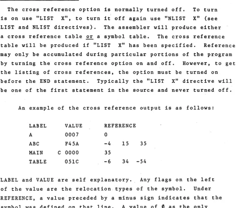
Cross Reference Format
The cross reference option is normally turned off. To turn is on use "LIST X", to turn it off again use "NLIST X" (see LIST and NLIST directives). The assembler will produce either a cross reference table or a symbol table. The cross reference table will be produced if "LIST X" has been specified. References may only be accumulated during particular portions of the program by turning the cross reference option on and off. However, to get the listing of ~ross references, the option must be turned on
before the END statement. Typically the "LIST X" directive will be one of the first statement in the source and never turned off.
An example of the cross reference output is as follows:
LABEL VALUE REFERENCE
A 0007
a
ABC F45A -4 15 35
MAIN C 0000 35
TABLE 05lC -6 34
-54
LABEL and VALUE are self explanatory. Any flags on the left of the value are the relocation types of the symbol. Under REFERENCE, a value preceded by a minus sign indicates that the
symbol was defined on that line. A value of
0
as the only entry on the line indicates this is an internal system symbol [image:68.618.77.556.88.510.2]APPENDIX A
ASSEMBLER ERROR CODES
If errors in the source code are detected during the
assembly process, an indication of the type of error is printed on the listing on the same line as the statement in error.
The following list should serve as a guide to diagnose the error. The listing always displays a total error count.
A - Argument error. The argument is missing or contains an illegal character.
C - Macro Substitution error. When substituting actual macro parameters for formal macro paramters, the 80 column source line limit was exceeded.
D - Duplicate Label error. The label in the statement has previously appeared in the label field. A label on SET directive previously appeared in a statement
L - Label error. A label contains an invalid character of starts with a numeric character.
M - Missing Label. This statement requires a label.
N - Macro Nesting error. When nesting macros the available number of levels was exceeded.
o -
Opcode error. The opcode mnemonic has not been recognized as a valid mnemonic, directive, or amacro call. Also a macro defined within another macro or conditional statements nested too deeply. ELSE, ENDIF, or ENDM used without preceding IF or MACRO. LOCAL directive used outside of MACRO body or more than one NAME directive in a program.
R - Register error. The register expression could not be evaluated or when evaluated was greater than 7 or less than O. The register field was not found or a specified register is not valid for the given opcode.
S - Syntax error. A rule of syntax has been violated in the statement. Parenthesis are not nested
properly or possibly two operators appear in sequence.
v -
Value error. An evaluated expression or constant is out of range for the field of the actual machine instruction in which it is to be contained. A one byte value is relocatable but was not preceded by a.LOW. or .HIGH. operator. In this case it is forced .LOW.
APPENDIX B
ASCII AND EBCDIC CODES
The Assembler will recognize only the following characters. The equivalent codes are expressed in hexadecimal notation.
CHARACTER ASCII EBCDIC CHARACTER ASCII EBCDIC
0
30 F0 V 56 E51 31 Fl W 57 E6
2 32 F2 X 58 E7
3 33 F3 y 59 E8
4 34. F4 Z 5A E9
5 35 F5
6 36 F6 blank 20 40
7 37 F7 21 5A
8 38 F8 II
22 7F
9 39 F9 1/ 23 7B
$ 24 5B
A 41 Cl % 25 6C
B 4'2 C2 & 26 ·50
C 43 .C3 27 7D
D 44 C4 ( 28 4D
E 45 C5 ) 29 5D
F 46 C6
*
2A 5CG 47 C7
+
2B 4FH 48 C8 2C 6B
I 49 C9 2D 60
J 4A Dl 2E 4B
K 4B D2
/
2F 61L 4C D3
M 4D D4 3A 7A
N 4E D5 3B 5E
a
4F D6 < 3C 4CP 50 D7
=
3D 7EQ 51 D8 > 3E 6E
APPENDIX C
8080/8085 OPERATION CODES
The following table illustrates the proper format for writing 8080/8085 instruct~ons. The operation code mnemonics listed are the only valid opcodes for the assembler.
These symbols are used in the table.
D,S -
indicates a source or destination register which is one of the following: A,B,C,D,E,H,L,MRP - indicates a register pair which may be one of the following: B,D,H,SP
PSW - indicates the Program Status Word eXPa - indicates an 8 bit value
eXP
1
6 -
indicates a 16 bit valueddd - the bit pattern representing one of the registers
555
denoted by D or S above. follows:
The bit patterns are as
B -
000E -
011M - 110
C - 001
H - 100 A - I l l
D - 010 L - 101
rp - the bit pattern representing one of the register pairs denoted by RP above. The bit patterns are as follows:
SYMSOLIC
FIRST BYTE
NUMBER
NUMBER
OPCODE
MACHINE CODE
OF BYTES
OF STATES
So So SOS5
Data Transfer
MOV
D,S
01ddd555
1
5
4
MOV
D,M
01dddll0
1
7
7
MOV
M,S
01110555
1
7
7
MVI
D,exPS'
00dddll0
27
7
MVI
M,exPS
001 101 1 0
21 0
10
LXI
RP, exP 16
OOrpOOOl
31 0
1 0
LOA
eXP16
00111010
31
31 3
STA
eXP16
00110010 .
3
1
3
1 3
LHLD eXP16
00101010
3
1 6
1 6
SHLD eXP16
00100010
3
1 6
1 6
LDAX RP
00rpl0l0
1
7
7
STAX RP
00rp0010
1
7
7
XCHG
11101011
1
4
4
Arithmetic Groue
ADD
S
10000555
1
4
4
ADC
S
1 0001 5'55
1
4
4
SUS
S
10010555
1
4
4
SBS
S
10011555
1
4
4
ADI
exPS
1100