USPEX
A
Copyright
Copyright © 1997 Auspex Systems, Inc. All rights reserved. Printed in the United States of America. Part Number 85-0372 Revision A, March 1997.
No part of this publication may be reproduced, in any form or by any means, without the prior written consent of Auspex Systems, Inc.
Auspex Systems, Inc., reserves the right to revise this publication and edit content from time to time without obligation on the part of Auspex Systems to provide prior notification of such revision or change.
RESTRICTED RIGHTS LEGEND: Use, duplication, or disclosure by the Government is subject to restrictions as set forth in subparagraph (c)(1)(ii) of the Rights in Technical Data and Computer Software Clause at DFARS 252.227-7013 (October 1988) and FAR
52.227-19(c) (June 1987) and in similar clauses in the FAR and NASA FAR supplement.
Trademarks
Auspex, Auspex logo design, Functional Multiprocessor, Functional Multi-processor, Functional Multi-processing, Functional Multiprocessing Kernel, FMK, FMP, and NS 5000 are registered trademarks of Auspex Systems, Inc. NS 7000, NS 6000, NS 6002, NS 5500, NS 5502, NS 3000, NetServer, DataGuard, ServerGuard, and Functional Multiprocessing are trademarks of Auspex Systems, Inc.
SPARC is a registered trademark of SPARC International. Sun, SunOS, Network File System, NFS, and Sun Microsystems are trademarks or registered trademarks of Sun Microsystems, Inc. UNIX is a registered trademark of X/Open Company Limited. VMEbus is a trademark of VMEbus Manufacturers Group. VT510 and DEC are trademarks of Digital Equipment Corporation. ForeRunner is a trademark of FORE Systems, Inc.
FCC Statement
WARNING: This equipment has been tested and found compliant with the limits for a Class A digital device, pursuant to Part 15 of the FCC rules. These limits are designed to provide reasonable protection against harmful interference when the equipment is operated in a commercial environment. This equipment generates, uses, and can radiate radio frequency energy and, if not installed and used in accordance with the instruction manual, may cause harmful interference in which case the user will be required to correct the interference at their own expense.
Protection Against Electrostatic Discharge
To prevent damage to the system due to electrostatic discharge, always wear the antistatic wrist strap provided with your network server when you come in contact with the system. Auspex Systems, Inc.
5200 Great America Parkway Santa Clara, California 95054 Phone: (408) 986-2000
Fax: (408) 986-2020
Internet: [email protected]
Declaration of Conformity
The NS 7000/700 Series NetServer meets the following safety and EMC standards pursuant to ISO/IEC Guide 22 and EN 45014:
The NetServer complies with the requirements of the Low Voltage Directive 73/23/EEC and the EMC Directive 89/336/EEC. This equipment has been tested and found compliant pursuant to CISPR22/85 Class A.
Publication Change Record
The following table records all revisions to this publication. The first entry is always the publication’s initial release. Each entry indicates the date of the release and the number of the system release to which the revision corresponds.
NetServer Model Number Standards
NS 7000/700 Series NetServer: NS 7000/700 (base cabinet) NS 7000/060 (expansion cabinet)
EN60950/1992 EN60950 A1/1993 EN60950 At2/1993 DIN VDE 0805 A1/11.91 EN55022 Class A (1985 Ed 1) EN50082-1 (Draft 1992)
IEC801-2 (1991): ESD, 8 kv air, 4 kv contact IEC801-3 (1984): RS, 10 v/m, 1 kHz modulated IEC801-4 (1988): EFT, 2 kv A/C cables,
1 kv I/O cables
IEC801-5 (Draft 1993): Surge, 2 kv diff, 4 kv comm NS 7000/050 (expansion cabinet)
NS 7000/052 (expansion cabinet)
EN60950/06.88 EN60950 A1/08.90 DIN VDE 0805 A1/11.91 EN55022 Class A (1985 Ed 1) EN50082-2 (Draft 1992)
IEC801-2 (1991): ESD, 8 kv air, 4 kv contact IEC801-3 (1984): RS, 3 v/m, 1 kHz modulated IEC801-4 (1988): EFT, 2 kv A/C cables, 1 kv I/O cables
IEC801-5 (Draft 1993): Surge, 1 kv diff, 2 kv comm
Part Number Date Description
NS 7000 Model 700 Series Hardware Manual ▲ Contents ▲ v
Noble:All Files - aedwards:1.9_7000_700_HWM:HWIG TOC;Feb-ruary 11, 1997 3:41 pm
USPEX
A
Contents
Chapter 1 Overview of the NS 7000/700
Overview . . . 1-1 Processor Board Configurations . . . 1-5 Disk Subsystems . . . 1-6 Numbering Conventions. . . 1-7 Environmental Requirements. . . 1-8 Space Requirements . . . 1-8 Electrical Requirements . . . 1-9 Base Cabinet and NS 7000/060 Expansion Cabinet . . . 1-9 NS 7000/050 Expansion Cabinet. . . 1-10 Power Cables . . . 1-11 North American . . . 1-11 International (except for Canada and Mexico). . . 1-11
Chapter 2 Unpacking and Setting Up the System
About This Chapter . . . 2-1 Unpacking the NetServer . . . 2-2 Unpacking a NetServer Shipped by Truck . . . 2-2 Unpacking a NetServer Shipped by Air. . . 2-3 Stabilizing the Cabinet. . . 2-5 Opening the Cabinet Doors . . . 2-5 Basic Components . . . 2-6 NetServer Base Cabinet Subassemblies . . . 2-8 Expansion Cabinet Subassemblies. . . 2-11 Card Cage Components . . . 2-18 Host Processor . . . 2-18 Network Processor . . . 2-20 Storage Processor. . . 2-21 Processor Board Slot Assignments. . . 2-22 Power Supply Configurations . . . 2-23 Base Cabinet and NS 7000/060 Expansion Cabinet . . . 2-23 NS 7000/052 Expansion Cabinet. . . 2-24
Chapter 3 Installation
vi ▲ Contents ▲ NS 7000 Model 700 Series Hardware Manual
Ethernet Addresses . . . .3-20 Installing Drives . . . .3-21 Drive Slot Numbering. . . .3-21 Installing a Drive . . . .3-25 Attaching a SCSI Device to the HP . . . .3-27
Chapter 4 Power On and Shut Down
About This Chapter . . . .4-1 Powering On the NetServer . . . .4-2 Power-On Self Test and Boot Sequence . . . .4-3 Processor Board LED Displays . . . .4-10
Host Processor . . . .4-10 Network Processor . . . .4-10 ATM LEDs . . . .4-10 Ethernet LEDs . . . .4-11 FDDI-SAS LEDs . . . .4-12 FDDI-DAS LEDs . . . .4-13
Chapter 5 Preventive Maintenance
About This Chapter . . . .5-1 Redundant Power Supply Operation . . . .5-2 NetServer Base Cabinet and NS 7000/060 Expansion Cabinet. . . .5-2 NS 7000/052 Expansion Cabinet . . . .5-3 Cleaning the NetServer Air Filter. . . .5-5 Fan Trays and LEDs . . . .5-7 Exabyte Tape Maintenance . . . .5-8 Cleaning the Tape Drives . . . .5-8 Maintaining the Tape Media . . . .5-8 Displaying Tape Statistics. . . .5-9 LED Display on the Exabyte Tape Drive . . . .5-10 Replacing the Fuse on the HP. . . .5-11 Identifying a Blown Fuse . . . .5-11 Replacing a Fuse . . . .5-11 Fuse Types. . . .5-12
Appendix A Drive Configuration Options
About This Appendix. . . A-1 Drive Configuration Guidelines. . . A-2 Drive Naming Conventions . . . A-3 Disk Drive Naming Conventions . . . A-3 Tape Drive Naming Conventions . . . A-3 CD-ROM Drive Naming Conventions . . . A-3 Sample Drive Configurations . . . A-4 Verifying and Changing Jumper Settings . . . A-11
When to Change the SCSI ID . . . A-11 Changing the SCSI ID of a Disk, Tape, or CD-ROM Drive . . . A-11 Adding or Removing Drives. . . A-16 Removing a Drive . . . A-16 Adding or Relocating a Drive . . . A-17 Mapping SCSI Cables to Drives . . . A-19 Base Cabinet and NS 7000/060 Expansion Cabinet . . . A-19 NS 7000/050 Expansion Cabinet . . . A-19
Appendix B Cable Specifications
NS 7000 Model 700 Series Hardware Manual ▲ Contents ▲ vii
Console Cable . . . .B-2 HP SCSI Port . . . .B-3 SCSI Drive Cabling. . . .B-4 Base Cabinet and NS 7000/060 Expansion Cabinet . . . .B-4 NS 7000/050 Expansion Cabinet. . . .B-5 Network Cables . . . .B-9 10Base-T Ethernet . . . .B-9 100Base-T Ethernet (half or full duplex) . . . .B-9 FDDI . . . .B-9 MLT-3 . . . .B-9 ATM . . . .B-10
Appendix C System Console Configurations
NS 7000 Model 700 Series Hardware Manual ▲ Figures ▲ ix
Noble:All Files - aedwards:1.9_7000_700_HWM:HWIG LOF;Feb-ruary 11, 1997 3:41 pm
USPEX
A
Figures
Figure 1-1. NS 7000/700 Series NetServer . . . 1-2 Figure 1-2. FMP architecture. . . 1-4 Figure 1-3. Outline of the L6-20P and L5-20P plugs . . . 1-11
Figure 2-1. Stabilizing the cabinet . . . 2-5 Figure 2-2. System cables . . . 2-7 Figure 2-3. Base cabinet subassemblies (front view) . . . 2-9 Figure 2-4. Base cabinet subassemblies (back view) . . . 2-10 Figure 2-5. NS 7000/060 expansion cabinet (front view) . . . 2-12 Figure 2-6. NS 7000/060 expansion cabinet (back view) . . . 2-13 Figure 2-7. NS 7000/050 expansion cabinet (front view) . . . 2-14 Figure 2-8. NS 7000/050 expansion cabinet (back view) . . . 2-15 Figure 2-9. NS 7000/052 expansion cabinet (front view) . . . 2-16 Figure 2-10. NS 7000/052 expansion cabinet (back view) . . . 2-17 Figure 2-11. Host Processor front panel connectors . . . 2-19 Figure 2-12. System processors. . . 2-21
Figure 3-1. Main power switch (back view of base cabinet) . . . 3-2 Figure 3-2. Main power switch (back view of expansion cabinet) . . . 3-3 Figure 3-3. Antistatic wrist strap . . . 3-4 Figure 3-4. Back view of connected cabinets . . . 3-7 Figure 3-5. Routing cables to the NetServer . . . 3-11 Figure 3-6. Connection to 10Base-T Ethernet ports . . . 3-13 Figure 3-7. Connection to 100Base-T Ethernet ports . . . 3-14 Figure 3-8. Connection to full-duplex 100Base-T ports . . . 3-14 Figure 3-9. Connection to FDDI (fiber) ports . . . 3-15 Figure 3-10. Connection to FDDI (MLT-3) ports . . . 3-15 Figure 3-11. Connection to ATM (fiber) ports . . . 3-16 Figure 3-12. Mixed NP network interfaces . . . 3-17 Figure 3-13. Mixed NP interface numbering . . . 3-19 Figure 3-14. Base cabinet drive slot numbering. . . 3-22 Figure 3-15. NS 7000/060 expansion cabinet drive slot numbering . . . 3-23 Figure 3-16. NS 7000/050 expansion cabinet drive slot numbering . . . 3-24 Figure 3-17. Installing a drive . . . 3-26
x ▲ Figures ▲ NS 7000 Model 700 Series Hardware Manual
Figure 5-2. NS 7000/052 redundant power supplies and LEDs . . . .5-3 Figure 5-3. EMI screen location . . . .5-5 Figure 5-4. Air filter location (front view of base cabinet) . . . .5-6 Figure 5-5. Fan trays (front view of base cabinet) . . . .5-7 Figure 5-6. Fan tray LEDs (back view of base cabinet) . . . .5-7 Figure 5-7. HP fuse holder types . . . .5-12
Figure A-1. Sample drive configuration . . . A-4 Figure A-2. Sample drive configuration with expansion rack . . . A-4 Figure A-3. Base cabinet drive names (front) . . . A-5 Figure A-4. Base cabinet drive names (back). . . A-5 Figure A-5. First NS 7000/060 expansion cabinet drive names (front) . . . A-6 Figure A-6. First NS 7000/060 expansion cabinet drive names (back) . . . A-7 Figure A-7. Second NS 7000/060 expansion cabinet drive names (front). . . A-8 Figure A-8. Second NS 7000/060 expansion cabinet drive names (back) . . . A-9 Figure A-9. NS 7000/050 expansion cabinet disk drive names . . . A-10 Figure A-10. Example of a SCSI ID label . . . A-11 Figure A-11. Example of SCSI ID jumper location on a drive. . . A-12 Figure A-12. 663-MB disk SCSI ID jumper (HP) . . . A-12 Figure A-13. 1-GB disk SCSI ID jumper (HP) . . . A-12 Figure A-14. 1.35-GB disk SCSI ID jumper (HP) . . . A-13 Figure A-15. 2-GB disk SCSI ID jumper (HP) . . . A-13 Figure A-16. 3-GB disk SCSI ID jumper (Micropolis). . . A-13 Figure A-17. 4-GB disk SCSI ID jumper (Seagate) . . . A-13 Figure A-18. 9-GB disk SCSI ID jumper (Seagate) . . . A-14 Figure A-19. 9-GB disk SCSI ID jumper (Micropolis). . . A-14 Figure A-20. 4-mm tape drive SCSI ID jumper (Wang DAT 2000) . . . A-14 Figure A-21. 1/4-inch tape drive SCSI ID jumper . . . A-14 Figure A-22. 8-mm tape drive SCSI ID jumper (Exabyte 8505XL) . . . A-15 Figure A-23. CD-ROM drive SCSI ID jumper . . . A-15 Figure A-24. Removing a drive . . . A-17 Figure A-25. Mapping SCSI cables to drives in the NS 7000/050 (back view). . . A-20
NS 7000 Model 700 Series Hardware Manual ▲ Tables ▲ xi
Noble:All Files - aedwards:1.9_7000_700_HWM:HWIG LOT;Feb-ruary 11, 1997 3:42 pm
USPEX
A
Tables
Table 1-1. Hardware features . . . 1-3 Table 1-2. Processor board configuration options . . . 1-5 Table 1-3. Supported expansion cabinet configurations and disk capacity . . . 1-6 Table 1-4. Numbering conventions . . . 1-7 Table 1-5. Environmental requirements . . . 1-8 Table 1-6. Base cabinet and expansion cabinet dimensions . . . 1-8 Table 1-7. Electrical power requirements . . . 1-9 Table 1-8. Electrical specifications . . . 1-9 Table 1-9. Electrical power requirements . . . 1-10 Table 1-10. Electrical input specifications . . . 1-10
Table 2-1. Host Processor memory module configurations . . . 2-18 Table 2-2. Supported network interfaces . . . 2-20 Table 2-3. Network Processor memory configurations. . . 2-20 Table 2-4. Processor board slot allocations . . . 2-22 Table 2-5. Base cabinet power supply configuration rules . . . 2-23 Table 2-6. NS 7000/060 expansion cabinet power supply configuration rules . . . . 2-24
Table 3-1. Drive rack SCSI cable connections . . . 3-6 Table 3-2. Connecting SCSI cables from the NS 7000/050 . . . 3-8 Table 3-3. Console setup parameter values . . . 3-10 Table 3-4. Ethernet address numbering scheme for full-duplex 100Base-T. . . 3-20 Table 3-5. HP SCSI IDs and device names . . . 3-27
Table 4-1. RingOP LED indicators on the FDDI-DAS SBus card. . . 4-13
Table 5-1. NetServer power supply status indicators . . . 5-2 Table 5-2. NS 7000/052 power supply status indicators . . . 5-4 Table 5-3. Important LED combinations on the tape drive . . . 5-10
Table A-1. CD-ROM drive naming conventions. . . A-3
NS 7000 Model 700 Series Hardware Manual ▲ ▲ xiii
USPEX
A
Preface
About This Manual
This manual describes the Auspex NS 7000™ Model 700 Series NetServer™ and provides procedures for installing hardware components and peripherals. It is intended for users who are familiar with computer equipment installation procedures and network cabling. Before setting up the system or installing system components, Auspex recommends that you first read this entire manual to familiarize yourself with the server.
The manual covers the following:
▲ Overview of the NS 7000/700
▲ Unpacking and Setting Up the System ▲ Installation
▲ Power On and Shut Down
▲ Preventive Maintenance ▲ Drive Configuration Options ▲ Cable Specifications
xiv ▲ ▲ NS 7000 Model 700 Series Hardware Manual
Applicable Documentation
For additional information relevant to managing the NetServer, refer to the following documents:
▲ System Manager’sGuide, Auspex Systems, Inc. ▲ Command Reference Guide, Auspex Systems, Inc. ▲ Software Release Note, Auspex Systems, Inc.
Terminology
In this manual, the terms NS 7000 Model 700, NS 7000/700 NetServer, NetServer, and server refer to the NS 7000/700 Series NetServer. NS 7000/050, NS 7000/052, and NS 7000/060 refer to the companion expansion cabinets for the NS 7000/700. The NS 7000/052 expansion cabinet is an NS 7000/050 with redundant power supplies.
Typographical Conventions
In this manual, typefaces indicate different types of information. The following table lists these typographical conventions:
Special Messages
The following special messages are used in this manual:
Warning: Warnings alert you to the danger of personal injury and call attention to instructions you must follow for your personal safety.
Caution: Cautions call attention to instructions you must follow to prevent damage to system hardware or software or system data loss.
Note: Notes call attention to important information as you follow the procedures outlined in this manual.
Recommendation: Recommendations call attention to an item or procedure that is not required but might help improve performance, ease of use, or ease of installation or configuration.
Font Meaning
Typewriter Indicates a literal screen message.
Bold In a command line, indicates information to be entered exactly as shown. In text, indicates a command name or device name.
NS 7000 Model 700 Series Hardware Manual ▲ ▲ xv
USPEX
A
Auspex Customer Service
North America Customers
Customer service for North America can be reached 24 hours a day by dialing 1-800-328-7739.
International Customers
Customer service for International can be reached 24 hours a day by dialing the provided telephone number:
Electronic Mail Support
Customers can also obtain support through electronic mail at the following address: [email protected]
To comment on the content of this guide, send electronic mail to Auspex Technical Publications at the following address:
World Wide Web
To access information about Auspex Systems, Inc. and its products, use the following resource location on the World Wide Web:
http://www.auspex.com
* All telephone numbers except Poland, are toll free. Customers not listed should contact their authorized Auspex distributor.
Country or territory Telephone number*
NS 7000 Model 700 Series Hardware Manual ▲ Overview ▲ 1-1
USPEX
A
1
Overview of the NS 7000/700
Overview
NS 7000 Model 700 Series Hardware Manual ▲ Overview ▲ 1-3
Table 1-1 lists the NetServer’s hardware features.
Table 1-1. Hardware features
System architecture ▲ Functional Multiprocessor architecture with dedicated processors for network, file, UNIX, and storage processing.
▲ Host Processor that includes an Mbus-based, 90-MHz or 125-MHz SPARC processor with up to 384 MB of memory. The Host Processor provides one SCSI, two serial, and three SBus connections (two masters and one slave).
▲ Optional nonvolatile Write Accelerator for improved NFS write operations.
Enhanced VME backplane ▲ 14-slot Enhanced VME backplane for connecting the processor boards. The VME transfer speed is up to 100 MB per second between Network Processor III (NP III), Network Processor IV (NP IV), and Storage Processor V (SP V) boards, and up to 55 MB per second between all other NP and SP board combinations.
Subsystems ▲ High-performance storage subsystems: disk, tape, and CD-ROM drives are organized in racks of five or seven drives, with multiple racks supported.
▲ Disk, tape, and CD-ROM drives that can be removed or inserted while the NetServer is powered on.
▲ Tape storage devices that can be attached to the HP or SP (refer to the Storage Peripherals Manager’s Guide for more information).
Networking ▲ Connections for 10Base-T and 100Base-T Ethernet, FDDI, and ATM.
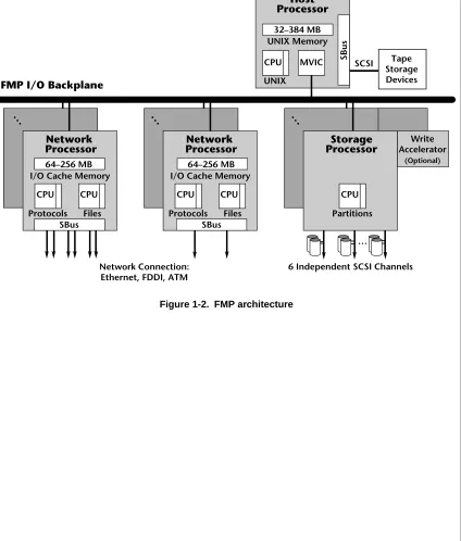
1-4 ▲ Overview ▲ NS 7000 Model 700 Series Hardware Manual Figure 1-2. FMP architecture
Network Connection: Ethernet, FDDI, ATM
6 Independent SCSI Channels
FMP I/O Backplane
UNIX Memory 32–384 MB
CPU MVIC
UNIX
SBus
I/O Cache Memory 64–256 MB
CPU CPU
Protocols Files
Network Processor
SBus
I/O Cache Memory 64–256 MB
CPU CPU
Protocols Files
Network Processor
SBus
…
… … …
Write Accelerator
(Optional)
SCSI Tape Storage Devices
Host Processor
CPU
Partitions
NS 7000 Model 700 Series Hardware Manual ▲ Overview ▲ 1-5
Processor Board Configurations
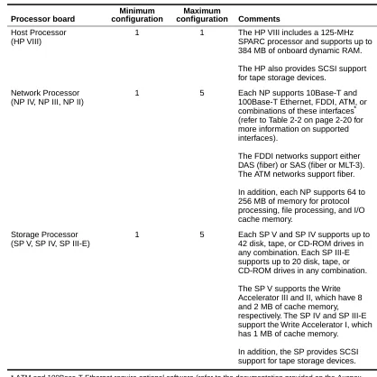
Table 1-2 lists the processor board configuration options supported by Version 1.9 software.
[image:21.612.136.554.138.556.2]* ATM and 100Base-T Ethernet require optional software (refer to the documentation provided on the Auspex Premier Software Series CD-ROM for more information).
Table 1-2. Processor board configuration options
Processor board
Minimum configuration
Maximum
configuration Comments
Host Processor (HP VIII)
1 1 The HP VIII includes a 125-MHz SPARC processor and supports up to 384 MB of onboard dynamic RAM.
The HP also provides SCSI support for tape storage devices.
Network Processor (NP IV, NP III, NP II)
1 5 Each NP supports 10Base-T and 100Base-T Ethernet, FDDI, ATM, or combinations of these interfaces* (refer to Table 2-2 on page 2-20 for more information on supported interfaces).
The FDDI networks support either DAS (fiber) or SAS (fiber or MLT-3). The ATM networks support fiber.
In addition, each NP supports 64 to 256 MB of memory for protocol processing, file processing, and I/O cache memory.
Storage Processor (SP V, SP IV, SP III-E)
1 5 Each SP V and SP IV supports up to 42 disk, tape, or CD-ROM drives in any combination. Each SP III-E supports up to 20 disk, tape, or CD-ROM drives in any combination.
The SP V supports the Write Accelerator III and II, which have 8 and 2 MB of cache memory, respectively. The SP IV and SP III-E support the Write Accelerator I, which has 1 MB of cache memory.
1-6 ▲ Overview ▲ NS 7000 Model 700 Series Hardware Manual
drives. The base cabinet supports up to 42 drives in 6 drive racks. The NS 7000/060 expansion cabinet supports up to 84 drives in 12 drive racks. Each drive rack holds 7 drives.
The NS 7000/050 expansion cabinet supports 5.25-inch disk, tape, and CD-ROM drives. The NS 7000/050 expansion cabinet supports up to 40 drives in eight drive racks, with each drive rack holding 5 drives.
The NetServer supports tape storage devices (refer to the Storage Peripherals Manager’s
Guide for more information).
Install the drives in any combination of disk, tape, or CD-ROM drives, except one disk drive must be the root drive.
With the availability of both 3.5-inch and 5.25-inch disk drives, multiple configurations of NS 7000/050 and NS 7000/060 expansion cabinets are supported with the base cabinet. Table 1-3 lists the supported expansion cabinet configurations and maximum disk drive capacities.
Table 1-3. Supported expansion cabinet configurations and disk capacity Cabinet configuration Number of disk drives
Base cabinet
NS 7000/050 expansion cabinet
42 4.2-GB disk drives
Base cabinet
NS 7000/060 expansion cabinet
42 4.2-GB disk drives 84 4.2-GB disk drives Base cabinet
NS 7000/060 expansion cabinet NS 7000/050 expansion cabinet
42 4.2-GB disk drives 84 4.2-GB disk drives
Base cabinet
Two NS 7000/060 expansion cabinets
NS 7000 Model 700 Series Hardware Manual ▲ Numbering Conventions ▲ 1-7
Numbering Conventions
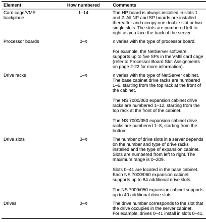
Table 1-4 describes the numbering conventions used to identify the various elements of the NetServer’s scalable design.
For information about the specific location and setup of system components and
[image:23.612.141.549.144.584.2]subassemblies, see Chapter 2. For information on how the NetServer software numbers the network interfaces, refer to “Connecting the NetServer to the Network” on page 3-12.
Table 1-4. Numbering conventions
Element How numbered Comments
Card cage/VME backplane
1–14 The HP board is always installed in slots 1 and 2. All NP and SP boards are installed thereafter and occupy one double slot or two single slots. The slots are numbered left to right as you face the back of the server. Processor boards 0–n n varies with the type of processor board.
For example, the NetServer software supports up to five SPs in the VME card cage (refer to Processor Board Slot Assignments on page 2-22 for more information).
Drive racks 1–n n varies with the type of NetServer cabinet. The base cabinet drive racks are numbered 1–6, starting from the top rack at the front of the cabinet.
The NS 7000/060 expansion cabinet drive racks are numbered 1–12, starting from the top rack at the front of the cabinet.
The NS 7000/050 expansion cabinet drive racks are numbered 1–8, starting from the bottom.
Drive slots 0–n The number of drive slots in a server depends on the number and type of drive racks installed and the type of expansion cabinet. Slots are numbered from left to right. The maximum range is 0–209.
Slots 0–41 are located in the base cabinet. Each NS 7000/060 expansion cabinet supports up to 84 additional drive slots.
The NS 7000/050 expansion cabinet supports up to 40 additional drive slots.
1-8 ▲ Environmental Requirements ▲ NS 7000 Model 700 Series Hardware Manual
the recommended levels of humidity. Table 1-5 lists the necessary environmental conditions.
The NetServer can operate at an altitude of up to 3,000 m (10,000 ft.). However, the maximum operating temperature at an altitude between 2,150 m ( 7,000 ft.) and 3,000 m (10,000 ft.) is 30° C (86° F). The 9-GB disk drive, supported in the NS 7000/050 expansion cabinet, has a maximum operating altitude of 1,800 m (6,000 ft.).
Space Requirements
Place the NetServer base cabinet in a location no less than three feet from the nearest wall or other equipment. Three feet of clearance allows easy access to the front and back of the server and permits adequate air circulation around the equipment.
If your server includes one or two expansion cabinets, you must allow enough space at the installation site, including three feet of clearance on all sides, for the base cabinet and the expansion cabinets to sit side by side, approximately two inches apart.
Table 1-6 gives the dimensions of the NetServer base cabinet and optional expansion cabinets. The weights shown are for a fully configured cabinet.
Table 1-5. Environmental requirements
Minimum Maximum
Operating temperature 5° C (40° F ) 40° C (104° F ) Storage temperature 0° C (32° F ) 65° C (150° F ) Operating altitude 0 m (0 ft.) 2,150 m (7,000 ft.) Storage altitude 0 m (0 ft.) 12,000 m (40,000 ft.) Operating humidity
(noncondensing at 40° C)
20% 80%
Nonoperating humidity (noncondensing at 40° C)
10% 90%
Audible noise N/A 75 dBA
Table 1-6. Base cabinet and expansion cabinet dimensions
Base cabinet
NS 7000/060 expansion cabinet
NS 7000/050 expansion cabinet
NS 7000 Model 700 Series Hardware Manual ▲ Electrical Requirements ▲ 1-9
Electrical Requirements
This section describes the electrical requirements for the NetServer base cabinet, the NS 7000/060 expansion cabinet, and the NS 7000/050 expansion cabinet.
Caution: If you have expansion cabinets connected to the NetServer, each expansion cabinet should be powered from a different circuit than the NetServer.
The NetServer requires an electrical power source that is free of surges and must be adequately grounded to protect it from electrostatic interference during operation. Maintaining proper environmental humidity also helps reduce the risk of electrostatic damage.
Warning: The wiring at your site must provide for ground fault protection. Avoid installation or reconfiguration during lightning storms.
Base Cabinet and NS 7000/060 Expansion Cabinet
Table 1-7 and Table 1-8 list the electrical power requirements and specifications for the base cabinet and NS 7000/060 expansion cabinet.
Caution: The base cabinet and NS 7000/060 expansion cabinet only accept a nominal input voltage range of 200 to 240 VAC. The NS 7000/050 expansion cabinet accepts a nominal input voltage of 100 to 240 VAC.
Caution: For proper air flow and EMI reduction, operate the NetServer with the doors closed and all access panels in place.
Table 1-7. Electrical power requirements
Base cabinet (42 drives) Expansion cabinet (84 drives)
2,800 W 2,250 W
2.800 KVA 2.250 KVA 9,600 BTUs/Hour 7,700 BTUs/Hour
Table 1-8. Electrical specifications
Nominal input voltage range 200–240 VAC Operating input voltage range 180–264 VAC Current rating 16 A
Input service rating 20 A Frequency 50–60 ±3 Hz
Inrush current 20 A peak max per power supply (up to three power supplies supported) Power factor 0.98
Turn-on time AC to DC = 3 seconds Electromagnetic Interference
(EMI) filter (conducted)
Class A
1-10 ▲ Electrical Requirements ▲ NS 7000 Model 700 Series Hardware Manual
fully configured system. Refer to Table 1-9 and Table 1-10 for the electrical power requirements and electrical input specifications.
Caution: For proper air flow and reduction in EMI, operate the NS 7000/050 expansion cabinet with the doors closed.
Caution: The NS 7000/050 expansion cabinet accepts a nominal input voltage of 100 to 240 VAC. The base cabinet and NS 7000/060 expansion cabinet accept a nominal input voltage range of 200 to 240 VAC.
Table 1-9. Electrical power requirements Expansion cabinet (40 drives)
1,700 W 1.7 KVA
5,800 BTUs/Hour
Table 1-10. Electrical input specifications Input Power supply
Nominal input voltage range 100–240 VAC Operating input voltage range 90–264 VAC Current rating 16 A Frequency 50–60 Hz Inrush current
Nonredundant power supply Redundant power supply
35 A peak max
87.5 A peak max per pair Power factor 0.99
NS 7000 Model 700 Series Hardware Manual ▲ Electrical Requirements ▲ 1-11
Power Cables
Two types of power cables are available with the NetServer.
North American
▲ Base Cabinet and NS 7000/060 Expansion Cabinet
The North American configuration is shipped with a 3-12 gauge power cable that has an L6-20P plug. The L6-20P plug requires that your site uses 220 V. The wall
receptacle for this configuration must be an L6-20R receptacle on a 16-amp circuit.
▲ NS 7000/050 Expansion Cabinet
The North American configuration is shipped with a 3-12 gauge power cable that has an L5-20P plug. The L5-20 plug is available for sites that use 125 V. The wall receptacle for this configuration must be an L5-20R receptacle on a 20-amp circuit. An optional L6-20 plug is available for sites that use 220 V. The optional configuration requires an L6-20 receptacle on a 20-amp circuit.
Figure 1-3 shows the outline of the L6-20P and L5-20P plugs.
Figure 1-3. Outline of the L6-20P and L5-20P plugs
International (except for Canada and Mexico)
The power cable for the international configuration is a TUV-approved 3x1.50-mm cable meeting the specifications of HD21 code H05VVF3G1.50. The cable has no plug. It is the customer’s responsibility to obtain a plug appropriate for the wall receptacle. The receptacle must be on a 16-amp circuit.
L5-20P plug (NS 7000/050) L6-20P plug
NS 7000 Model 700 Series Hardware Manual ▲ About This Chapter ▲ 2-1
2
Unpacking and Setting Up
the System
About This Chapter
This chapter provides instructions for unpacking and setting up the NetServer base cabinet and expansion cabinets and includes information to help you familiarize yourself with the NetServer’s components.
The chapter covers the following sections:
▲ Unpacking the NetServer ▲ Unpacking the NetServer ▲ Stabilizing the Cabinet ▲ Opening the Cabinet Doors ▲ Basic Components
▲ NetServer Base Cabinet Subassemblies ▲ Expansion Cabinet Subassemblies
▲ Card Cage Components
▲ Processor Board Slot Assignments ▲ Power Supply Configurations
2-2 ▲ Unpacking the NetServer ▲ NS 7000 Model 700 Series Hardware Manual
cabinets. This procedure varies depending on the shipping method and packing materials used.
Servers sent to destinations within the continental United States are usually shipped by truck, uncrated but wrapped in cardboard packing material. Servers sent to destinations outside the continental United States are crated and shipped by air.
Instructions for unpacking and installing other NetServer components appear in Chapter 3.
Warning: Do not attempt to move or uncrate the base cabinet unless you have others to assist you. You need at least one person to help you uncrate the expansion cabinet. Any attempt by one person to uncrate the base or expansion cabinets could result in injury. When empty, the base cabinet weighs approximately 700 pounds. The expansion cabinet weighs approximately 500 pounds.
Tools
▲ Knife to open the packing boxes containing drives and accessories ▲ Wire cutter to cut tie-wraps (cut only red tie-wraps)
▲ Crescent wrench for lowering stabilizers
If theserveris in a crate, you need the following:
▲ 9/16-inch wrench to remove the bolts securing the sides of the crate
▲ Band cutter or wire cutter to cut the straps securing the NetServerto the crate
Unpacking a NetServer Shipped by Truck
1. Place the NetServer base cabinet on the site prepared for it.
For easy access and proper air circulation, make sure there is at least three feet of clearance between the server and any wall or other equipment (except the expansion cabinets). Also, make sure there is a wall receptacle within six feet of the server and a telephone jack (for modem users) within seven feet of the base cabinet. The wall receptacle must be on a 20-amp circuit.
2. Remove the packing material from the base cabinet by sliding it up and off the unit. To avoid damaging the unit, do not cut the plastic packing material with a knife. 3. If your NetServer includes expansion cabinets:
a. Place the first expansion cabinet to the left of the base cabinet (when viewed from the front). If you are connecting a second expansion cabinet, place it to the right of the base cabinet (when viewed from the front).
NS 7000 Model 700 Series Hardware Manual ▲ Unpacking the NetServer ▲ 2-3
b. Remove the packing material as described in step 2. To connect the expansion cabinets to the base cabinet, contact your authorized Auspex service
representative.
Note: If the surface of the server becomes marked or smudged, use a nonabrasive stainless-steel cleaner to clean the surface.
Unpacking a NetServer Shipped by Air
Note: Be sure to allocate enough space for this procedure. You need at least 12 feet of unobstructed space on the side of the crate that is secured by metal clips, at least 8 feet of unobstructed space on the opposite side, and at least 3 feet on the remaining sides.
1. Use a 9/16-inch wrench to remove the seven bolts securing the side panels of the crate to its base.
2. Turn the six latch locks counterclockwise to release the locks securing the packing crate’s front panel. After releasing the locks, carefully lower the panel to the ground. Keep the panel nearby. It will be used in step 5 as a ramp to roll the server off the base of the crate.
3. The remaining side panels of the crate are constructed as a single unit. Slide the panels off the server, and move them aside.
4. Cut and remove the straps that secure the server to the base of the crate.
5. Place the ramp (the panel removed in step 2) next to the edge of the crate, adjacent to the back panel of the server. At the lower end of the ramp, fold out the ramp
extension to make a smooth transition from ramp to floor. 6. Carefully roll the server down the ramp to the floor.
Caution: Make sure that the high end of the ramp is slightly lower than the base of the crate, or theserver’s casters may move the ramp out of position as you roll it onto the ramp. Also, check that the leveling feet clear the upper edge of the ramp extension. If the feet catch on the extension, the cabinet can fall off the ramp.
7. Remove the plastic packing material from the server by sliding it up and off the unit. To avoid damaging the unit, do not cut the plastic packing material with a knife. 8. Before proceeding further, roll the server to the site prepared for it.
For easy access and proper air circulation, make sure there is at least three feet of clearance between the server and any wall or other equipment (except the expansion cabinets). Also, make sure that there is a wall receptacle within six feet of the server and a phone jack (for modem users) within seven feet of the base cabinet. The wall receptacle must be on a 16-amp circuit.
9. If your NetServer includes expansion cabinets, repeat steps 1 through 8 to unpack each one. Place the first expansion cabinet to the left of the base cabinet (when viewed from the front). If you are connecting a second expansion cabinet, place it to the right of the base cabinet (when viewed from the front).
2-4 ▲ Unpacking the NetServer ▲ NS 7000 Model 700 Series Hardware Manual
service representative.
NS 7000 Model 700 Series Hardware Manual ▲ Stabilizing the Cabinet ▲ 2-5
Stabilizing the Cabinet
Each cabinet is shipped resting on its casters so that you can easily roll it to its permanent site. Once you roll the server to its permanent site, you must level and stabilize it. The procedure is the same for both the base cabinet and expansion cabinet.
The following describes how to stabilize the cabinet:
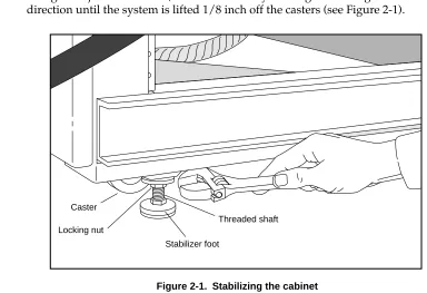
1. Locate the four cabinet stabilizer feet underneath each corner of the cabinet.
[image:33.612.138.522.186.449.2]2. Using an adjustable wrench, lower each foot by rotating the locking nut in a clockwise direction until the system is lifted 1/8 inch off the casters (see Figure 2-1).
Figure 2-1. Stabilizing the cabinet
3. Turn the locking nut counterclockwise until it reaches the top of the threaded shaft, and tighten it to lock the stabilizer foot in position. Make sure the foot does not turn as you tighten the locking nut.
This concludes the procedure for stabilizing the cabinet.
Opening the Cabinet Doors
The NetServer doors are unlocked with a system key. Once unlocked, you can open and close the doors without a key.
Two duplicate keys are tie-wrapped to the NetServer power cord. The keys open both the front and back doors of the cabinet. If your NetServer includes expansion cabinets, the same keys also open their front and back doors.
Caster
Locking nut
Threaded shaft
2-6 ▲ Basic Components ▲ NS 7000 Model 700 Series Hardware Manual
unpacking and stabilizing the NetServer, make sure you have the following:
▲ Disk drives (one minimum), packed separately in a foam-padded box, to install in the
base cabinet
▲ CD-ROM (one minimum) and optional 8-mm tape drives to install in the base cabinet,
packed separately in a foam-padded box
▲ Documentation set, including:
- NS 7000 Model 700 Series Hardware Manual(this manual) - System Manager's Guide
- System Manager’s Quick Reference
- Command Reference Guide
- Software release note
▲ System console (shipped in a separate carton)
▲ One null-modem RS-232C console cable (shipped in a separate carton)
▲ One power cable (installed inside the base cabinet and secured with red tie-wraps)
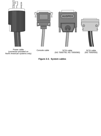
Refer to Figure 2-2 on page 2-7 to identify system cables shipped with your NetServer. Some cables, such as the SCSI cables that connect the drives in the base cabinet to the Storage Processor, are already installed within the server and should not be removed. Instructions for connecting cables appear in Chapter 3 in the sections “Grounding the NetServer,” “Connecting the System Console to the Server,” “Attaching a SCSI Device to the Host Processor,” and “Connecting the NetServer to the Network.”
If you ordered an expansion cabinet, make sure have the following:
▲ NetServer expansion cabinet ▲ Expansion cabinet connection kit
▲ Disk drives, packed separately in a foam-padded box, to install in the expansion
cabinet
▲ Any additional tape or CD-ROM drives, packed separately in a foam-padded box, to
install in the expansion cabinet
▲ One power cable (installed inside the expansion cabinet and secured with red
tie-wraps)
Note: To connect an expansion cabinet to the base cabinet, contact your authorized Auspex service representative.
The NS 7000/060 expansion cabinet accepts the same type of disk, CD-ROM, and tape drives as the base cabinet. The NS 7000/050 expansion cabinet supports 5.25-inch disk, tape, and CD-ROM drives from Auspex.
The following cables are included in each expansion cabinet (installed within the system and secured with red tie-wraps):
NS 7000 Model 700 Series Hardware Manual ▲ Basic Components ▲ 2-7
▲ Twelve SCSI cables that connect the drives in the expansion cabinet to the Storage
Processor IV or Storage Processor V boards in the base cabinet (NS 7000/060 only)
▲ Twelve SCSI drive cables that connect the drives in the expansion cabinet to the
Storage Processor III-E boards in the base cabinet (NS 7000/050 only)
[image:35.612.138.550.172.725.2]Instructions for connecting these cables appear in Chapter 3 in sections “Grounding the NetServer” and “Connecting the SCSI Drive Cables from the Expansion Cabinet.”
Figure 2-2. System cables
Power cable (connector provided on North American systems only)
Console cable SCSI cable
(NS 7000/700, NS 7000/060)
SCSI cable (NS 7000/050)
2-8 ▲ NetServer Base Cabinet Subassemblies ▲ NS 7000 Model 700 Series Hardware Manual
▲ Extended card cage chassis ▲ Drive racks (up to six)
▲ Power distribution unit (PDU)
▲ Power supply enclosure with one to three power supplies installed offering a
nonredundant or optional redundant configuration
NS 7000 Model 700 Series Hardware Manual ▲ NetServer Base Cabinet Subassemblies ▲ 2-9 Figure 2-3. Base cabinet subassemblies (front view)
System chassis
Side panel
Disk drive (in carrier)
Drive rack
Backplane
EMI screen
(air filter and fan trays located behind screen)
Power supplies Lower front
2-10 ▲ NetServer Base Cabinet Subassemblies ▲ NS 7000 Model 700 Series Hardware Manual Figure 2-4. Base cabinet subassemblies (back view)
Card cage
Power supply enclosure
PDU Back door
panel Wrist strap
Power cable
NS 7000 Model 700 Series Hardware Manual ▲ Expansion Cabinet Subassemblies ▲ 2-11
Expansion Cabinet Subassemblies
The NS 7000/050 and NS 7000/060 expansion cabinets contain the following subassemblies:
▲ Drive racks (up to 8 in the NS 7000/050 or up to 12 in the NS 7000/060)
▲ PDU
▲ NS 7000/060 power supply enclosure with one to three power supplies installed
offering a nonredundant or optional redundant configuration
▲ NS 7000/050 power supply enclosure with power supply installed
▲ Optional redundant power supply enclosure with power supplies installed
(NS 7000/052 only)
Figures 2-5 and 2-6 show the front and back views of an NS 7000/060 expansion cabinet with 12 drive racks.
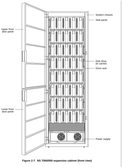
Figures 2-7 and 2-8 show the front and back views of an NS 7000/050 expansion cabinet with eight drive racks.
2-12 ▲ Expansion Cabinet Subassemblies ▲ NS 7000 Model 700 Series Hardware Manual Figure 2-5. NS 7000/060 expansion cabinet (front view)
System chassis
Side panel
Lower front door panel Upper front door panel
Disk drive (in carrier)
Drive rack
Power supplies
AC OK DC OK
ALM VOLT ADJ +5V +12V +5VD - + +12VD - + AC
OK DC OK
ALM VOLT ADJ +5V +12V +5VD - + +12VD - + AC
OK DC OK
NS 7000 Model 700 Series Hardware Manual ▲ Expansion Cabinet Subassemblies ▲ 2-13 Figure 2-6. NS 7000/060 expansion cabinet (back view)
Back door panel
PDU Drive rack
Main power switch Access panel
2-14 ▲ Expansion Cabinet Subassemblies ▲ NS 7000 Model 700 Series Hardware Manual Figure 2-7. NS 7000/050 expansion cabinet (front view)
System chassis
Side panel
Disk drive (in carrier)
Drive rack
Power supply Lower front
NS 7000 Model 700 Series Hardware Manual ▲ Expansion Cabinet Subassemblies ▲ 2-15 Figure 2-8. NS 7000/050 expansion cabinet (back view)
Power supply Back door
panel
PDU Drive rack Power distribution block
Fans
2-16 ▲ Expansion Cabinet Subassemblies ▲ NS 7000 Model 700 Series Hardware Manual Figure 2-9. NS 7000/052 expansion cabinet (front view)
Side panel
Redundant power supply for lower four drive racks Lower front
door panel Upper front door panel
Redundant power supply for upper four drive racks
PON –12V
PON
+ 5V ALM
+12V + 5V
ALM +12V
PON
–12V
PON + 5V ALM
+12V + 5V
ALM +12V
NS 7000 Model 700 Series Hardware Manual ▲ Expansion Cabinet Subassemblies ▲ 2-17 Figure 2-10. NS 7000/052 expansion cabinet (back view)
Back door panel Wrist strap
Redundant power supply for upper four drive racks
Power cable PDU Drive rack
Main power switch
2-18 ▲ Card Cage Components ▲ NS 7000 Model 700 Series Hardware Manual
▲ HP (one) ▲ NP (up to five) ▲ SP (up to five)
Each of these boards, their functions, and minimum and maximum configurations are described as follows.
Host Processor
The NS 7000/700 has one HP VII or HP VIII with several features:
▲ 90-MHz (HP VII) or 125-MHz (HP VIII) SPARC processor
▲ Two or four memory modules of 16–128 MB each for up to 384 MB of host memory
(see Table 2-1)
Caution: The HP does not support mixing single in-line memory modules (SIMMs). SIMMs must be installed in pairs of 16, 32, 64, or 128 MB.
▲ Accommodates up to three SBus cards, including three single, one double and one
single, or one triple SBus card
Note: Contact your authorized Auspex service representative for information on supported SBus cards.
▲ Support for serial connections on ttya and ttyb
▲ Integrated Mbus design allowing for future upgrades of the HP CPU ▲ Support for up to seven Sun-supported SCSI devices on one SCSI port
Table 2-1. Host Processor memory module configurations
Total memory (MB)
Number of 16-MB modules
Number of 32-MB modules
Number of 64-MB modules
Number of 128-MB modules
32 2 0 0 0
64 4 0 0 0
64 0 2 0 0
96 2 2 0 0
128 0 0 2 0
160 2 0 2 0
192 0 2 2 0
256 0 0 4 0
256 0 0 0 2
320 0 2 0 2
NS 7000 Model 700 Series Hardware Manual ▲ Card Cage Components ▲ 2-19
[image:47.612.139.531.107.656.2]▲ Support for tape storage devices
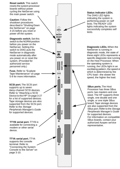
Figure 2-11 shows the front panel connectors on the Host Processor.
Figure 2-11. Host Processor front panel connectors
DIAG READY RESET RUN DIAG NORM DIAG LEDS SCSI TTYB TTYA
SCSI port. The SCSI port
supports up to seven daisy-chained SCSI devices. Refer to “Attaching a SCSI Device to the HP” on page 3-27 for a list of supported devices. Tape storage devices are also supported from the SCSI port. Refer to the Storage
Peripherals Manager’s Guide for supported devices.
Reset switch. This switch
resets the system processor boards without power cycling the NetServer using the main power switch.
Caution: Follow the
shutdown procedures described in “Shutting Down the NetServer” on page 4-15 before you reset or power off the system.
Diagnostic LEDs. When the
NetServer is running in diagnostic mode, the state of these eight LEDs represents a specific diagnostic test running on the Host Processor. When the operating system is running, the LEDs light in an oscillating pattern, the speed of which is determined by the CPU load—the slower the speed, the higher the load.
TTYB serial port. TTYB is
available for connecting a modem or other serial device.
TTYA serial port. TTYA
supports the console terminal. Refer to “Connecting the System Console to the Server” on page 3-10.
SBus ports. The Host
Processor has three SBus ports: two masters and one slave. The HP supports three single, one double and one single, or one triple SBus board. Tape storage devices are also supported from the SBus port. Refer to the Storage Peripherals Manager’s Guide for supported devices. For information on compatible SBus boards, contact your authorized Auspex service representative.
Status indicator LEDs.
The DIAG LED lights indicating the system is performing power on self tests. The READY LED lights indicating the system successfully completes self tests.
Diagnostic switch. Set this
switch to the NORM position before you power on the NetServer. Setting this switch to DIAG puts the NetServer in diagnostic mode automatically after you power on or reset the system. (Provided for authorized service personnel only.)
Fuse. Refer to “Exabyte
2-20 ▲ Card Cage Components ▲ NS 7000 Model 700 Series Hardware Manual
Ethernet, FDDI, ATM, or any combinations of these interfaces.
Note: ATM and 100Base-T Ethernet require optional software. Refer to the documentation provided on the Auspex Premier Software Series CD-ROM for more information.
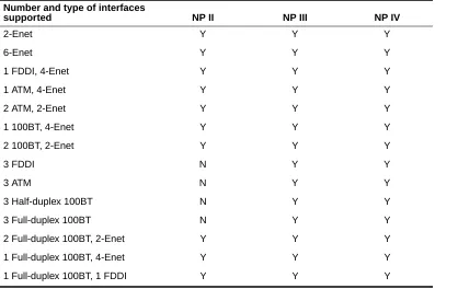
[image:48.612.55.473.214.478.2]Table 2-2 shows an example of the supported network interfaces for the NP boards.
Table 2-2. Supported network interfaces
Each NP has 64–256 MB of memory for protocol processing, file processing, and I/O cache memory. The NP III and NP IV have four or eight SIMMs of either 16 MB or 32 MB each. Memory must be installed in groups of four SIMMs of the same capacity. The NP II has one or two memory modules of either 64 MB or 128 MB each. Refer to Table 2-3 for supported memory configurations.
Number and type of interfaces
supported NP II NP III NP IV
2-Enet Y Y Y
6-Enet Y Y Y
1 FDDI, 4-Enet Y Y Y
1 ATM, 4-Enet Y Y Y
2 ATM, 2-Enet Y Y Y
1 100BT, 4-Enet Y Y Y
2 100BT, 2-Enet Y Y Y
3 FDDI N Y Y
3 ATM N Y Y
3 Half-duplex 100BT N Y Y
3 Full-duplex 100BT N Y Y
2 Full-duplex 100BT, 2-Enet Y Y Y 1 Full-duplex 100BT, 4-Enet Y Y Y 1 Full-duplex 100BT, 1 FDDI Y Y Y
Table 2-3. Network Processor memory configurations
NP IV/III NP II Total memory
(MB)
Number of 16-MB SIMMs
Number of 32-MB SIMMs
Number of 64-MB modules
Number of 128-MB modules
64 4 0 1 0
128 8 0 2 0
128 0 4 0 1
192 4 4 1 1
NS 7000 Model 700 Series Hardware Manual ▲ Card Cage Components ▲ 2-21
The NP III and NP IV have a VME transfer speed of up to 100 MB per second when operating in conjunction with an SP V board. The NP II has a VME transfer speed of up to 55 MB per second when operating in conjunction with either an SP IV or an SP V board.
Storage Processor
The NS 7000/700 uses one to five SP IV or SP V boards, each with six parallel SCSI channels for disk, tape, and CD-ROM drives. Each SP can have an optional Write Accelerator board added to enhance NFS write operations. The SP V supports the Write Accelerator II and Write Accelerator III, which have 2 and 8 MB of cache memory, respectively. The SP IV supports the Write Accelerator I, which has 1 MB of cache memory. As an option, you can have up to two SP III-E boards, each with 10 parallel SCSI channels for disk, tape, and CD-ROM drives. The SP III-E has 1 MB of onboard memory for higher data throughput and supports the Write Accelerator I board.
[image:49.612.141.520.344.682.2]The SP III-E and SP IV have a VME transfer speed of up to 55 MB per second when operating in conjunction with either an NP II, NP III, or NP IV. The SP V has a VME transfer speed of up to 100 MB per second when operating in conjunction with an NP III or NP IV.
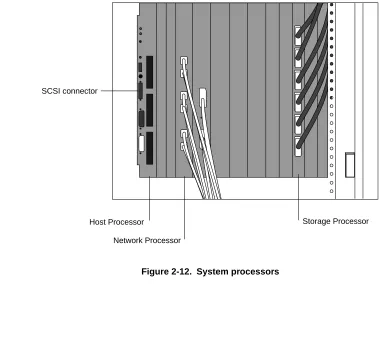
Figure 2-12 shows a card cage configuration with network connections.
Figure 2-12. System processors
SCSI connector
Host Processor
Network Processor
2-22 ▲ Processor Board Slot Assignments ▲ NS 7000 Model 700 Series Hardware Manual
configurations, refer to “Processor Board Configurations” on page 1-5. Table 2-4 shows the slot allocations listed for each processor board.
Table 2-4. Processor board slot allocations
Caution: If you have a base cabinet with mixed expansion cabinets (that is, one NS 7000/060 expansion cabinet and one NS 7000/050 expansion cabinet), the SP III-E boards controlling the NS 7000/050 expansion cabinet are
installed in slots 12 and 13. SP III-E boards must occupy higher-numbered slots than the NP boards to function properly.
If you have a base cabinet with one expansion cabinet
▲ The Host Processor board is installed in slots 1 and 2.
▲ Starting in slot 5, Network Processor boards are installed (up to five). ▲ Slot 11 is reserved for future use.
▲ Starting in slot 12, Storage Processor boards are installed (up to three).
Note: Slots 2 and 10 are not accessible individually. Slots 5, 6, 7, and 8 are double-width slots. Slots 9 and 10 serve as the fifth double-width slot for NP boards.
If you have a base cabinet with two expansion cabinets
▲ The Host Processor is installed in slots 1 and 2.
▲ The fourth and fifth Storage Processor boards are installed in slots 3 and 4 (numbered
SP3 and SP4 by the system software).
▲ Starting in slot 5, Network Processor boards are installed (up to five). ▲ Slot 11 is reserved for future use.
▲ Starting in slot 12, the first three Storage Processor boards are installed (numbered
SP0, SP1, and SP2 by the system software).
Note: Slots 2 and 10 are not accessible individually. Slots 5, 6, 7, and 8 are double-width slots. Slots 9 and 10 serve as the fifth double-width slot for NP boards.
Slot
Processor board 1 2 3 4 5 6 7 8 9 10 11 12 13 14
Host Processor
Network Processor
NS 7000 Model 700 Series Hardware Manual ▲ Power Supply Configurations ▲ 2-23
Power Supply Configurations
This section describes the redundant and nonredundant power supply requirements for the base cabinet and NS 7000/060 expansion cabinet and the redundant configuration for the NS 7000/052 expansion cabinet.
In a redundant configuration, if one power supply fails, the remaining power supply keeps the NetServer operating. When this occurs, the failed power supply can be hot-plugged while the server is running off the remaining supply. Power supplies can also be
hot-plugged when your configuration requires additional power.
Base Cabinet and NS 7000/060 Expansion Cabinet
The base cabinet and NS 7000/060 expansion cabinet support up to three power supplies each. These power supplies share the power requirements of the NetServer.
Note: If you need to install or replace a power supply, contact your authorized Auspex service representative.
Table 2-5 lists the number of power supplies needed to operate the base cabinet in a nonredundant state. For redundant operation, add an additional power supply.
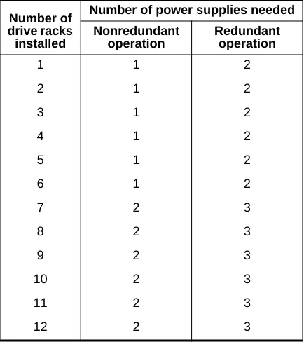
Table 2-6 lists the number of power supplies needed to operate the NS 7000/060 expansion cabinet in nonredundant and redundant states.
Table 2-5. Base cabinet power supply configuration rules Number of power supplies required Number of
drive racks installed
Number of processor boards installed
3 4 5 6 7 8 9 10 11
1 1 1 1 1 2 2 2 2 2
2 1 1 1 2 2 2 2 2 2
3 1 1 2 2 2 2 2 2 2
4 1 2 2 2 2 2 2 2 2
5 2 2 2 2 2 2 2 2 2
2-24 ▲ Power Supply Configurations ▲ NS 7000 Model 700 Series Hardware Manual
Empty power supply slots are covered with an access panel for proper air flow and EMI reduction.
For inspection procedures and maintenance instructions for the power supplies, refer to “Redundant Power Supply Operation” in Chapter 5.
NS 7000/052 Expansion Cabinet
The NS 7000/052 is configured at the factory with two or four power supplies (each pair supports an array of up to 20 drives). Two power supplies are located below the bottom drive rack (drive rack 1). They share the current demands of the drive arrays in the lower four drive racks. If one of the power supplies fail, the remaining supply keeps the system operating.
Note: Adding or replacing a power supply in the NS 7000/052 requires shutting down the NetServer.
If the upper four drive racks are installed in the expansion cabinet, two power supplies are located between drive racks 4 and 5 to provide power to the additional drive arrays (refer to Figure 2-9 on page 2-16 for power supply locations).
For more information on redundant supplies, refer to “Redundant Power Supply Operation” in Chapter 5.
drive racks installed
Nonredundant operation
Redundant operation
1 1 2
2 1 2
3 1 2
4 1 2
5 1 2
6 1 2
7 2 3
8 2 3
9 2 3
10 2 3
11 2 3
[image:52.612.54.271.90.334.2]NS 7000 Model 700 Series Hardware Manual ▲ About This Chapter ▲ 3-1
3
Installation
About This Chapter
This chapter describes installing NetServer components. It does not describe installing card cage components, such as processor boards and memory modules.
This chapter covers the following sections:
▲ Grounding the NetServer
▲ Installing the Antistatic Wrist Strap
▲ Connecting the SCSI Drive Cables from the Expansion Cabinet ▲ Connecting the System Console to the Server
▲ Connecting the NetServer to the Network ▲ Installing Drives
▲ Attaching a SCSI Device to the HP
Note: The NetServer is configured at the factory to match your order. Additional processor boards, processor board memory, and drives are available as optional equipment. If you are adding or replacing a board or module in your NetServer, contact your authorized Auspex service representative for assistance.
Caution: Do not cut the black or white tie-wraps. The black and white tie-wraps hold bundles of cables together and keep them out of the way during system operation and drive installation. Throughout the procedures in this chapter, when you are instructed to cut tie-wraps to free needed cables or components, remember to cut only red tie-wraps.
3-2 ▲ Grounding the NetServer ▲ NS 7000 Model 700 Series Hardware Manual
power cord for each cabinet to create a ground path for the antistatic wrist strap. Warning: The wiring at your site must provide for ground fault protection.
Tools
▲ Knife to open the packing boxes containing drives and accessories ▲ Wire cutter to cut tie-wraps (cut only red tie-wraps)
▲ 3/16-inch flat-blade screwdriver to attach the console cable ▲ 7/16-inch nut driver
▲ #2 Phillips screwdriver
1. Locate the main power switch on the PDU at the bottom of the base cabinet, and set it to OFF (O). Figure 3-1 shows the location of the switch in the base cabinet.
Caution: Use the main power switch on the PDU only. The switch at the top of each power supply should always be ON ( — ).
Figure 3-1. Main power switch (back view of base cabinet)
2. If your NetServer includes an expansion cabinet, locate the main power switch on the PDU at the bottom of the expansion cabinet. Set this switch to OFF (O). Figure 3-2 shows the location of the switch in the expansion cabinet.
Caution: Use the main power switch on the PDU only. For the NS 7000/060 expansion cabinet, the switch at the top of each power supply located should always be ON ( — ).
NS 7000 Model 700 Series Hardware Manual ▲ Grounding the NetServer ▲ 3-3 Figure 3-2. Main power switch (back view of expansion cabinet)
3. Locate the power cable for each cabinet.
On the base cabinet, the cable is hanging on the left side of the cabinet, secured with red tie-wraps. On the expansion cabinet, the cable is coiled on top of the panel covering the power supply.
4. Cut the red tie-wraps to release the power cable, and plug the appropriate end to the back of the PDU.
5. Tighten the strain relief surrounding the plug at the PDU.
6. After ensuring the power to the system is off, route each power cable to a separate grounded outlet, and plug it in. The outlet must be on a 16 amp-rated circuit for the base cabinet and the NS 7000/060 expansion cabinet, and a 20 amp-rated circuit for the NS 7000/050 expansion cabinet.
Caution: Do not power on the server at this time. You connected the power cable only to provide a ground path for the antistatic wrist strap. Do not power on the NetServer until instructed to do so later in this manual.
This concludes the procedure for grounding the NetServer. Proceed to section “Installing the Antistatic Wrist Strap” on page 3-4.
Main power switch PDU
3-4 ▲ Installing the Antistatic Wrist Strap ▲ NS 7000 Model 700 Series Hardware Manual
electrostatic damage to the NetServer, always wear the antistatic wrist strap when you come in contact with electrostatic-sensitive equipment.
Note: The wrist strap cannot prevent electrostatic damage to system components until the power cable is plugged into a grounded power receptacle.
The base cabinet and expansion cabinets have two wrist strap jacks each, one on the left chassis frame rail inside the upper front door and one on the left chassis frame rail inside the back door.
One wrist strap is provided with each cabinet. On the base cabinet, the strap is attached to the back jack. On the expansion cabinet, the strap is attached to the front jack.
1. Cut the red tie-wraps holding the wrist strap to the chassis frame rail hook.
2. To use the wrist strap, remove the strap from the hook and slide it around your wrist, as shown in Figure 3-3.
Note: When you are not using the wrist strap, remember to hang it on the hook.
[image:56.612.106.469.372.682.2]3. As you move between the front and back of the system, you can unplug the wrist strap from one jack into another.
Figure 3-3. Antistatic wrist strap
Wrist strap Chassis
frame rail
NS 7000 Model 700 Series Hardware Manual ▲ Connecting the SCSI Drive Cables from the Expansion Cabinet ▲ 3-5
Connecting the SCSI Drive Cables from the
Expansion Cabinet
Optional expansion cabinets are available from Auspex. This section describes how to connect the cables to the Storage Processor boards in the base cabinet and how to route the SCSIcables from each expansion cabinet to the base cabinet. The procedure assumes that the base cabinet and the expansion cabinet are properly connected.
Note: If you need to connect an expansion cabinet to the base cabinet, contact your authorized Auspex service representative.
The SCSI cables from the NS 7000/060 expansion cabinet must be connected to an SP IV or SP V board in the base cabinet. The SCSI cables from the NS 7000/050 expansion cabinet must be connected to an SP III-E board.
NS 7000/060 Expansion Cabinet SCSI Cabling
The NS 7000/060 expansion cabinet is shipped with twelve SCSI cables installed inside the cabinet. The following procedure describes how to connect the SCSI cables to the SP IV or SP V board in the base cabinet. The procedure assumes that the base cabinet and the expansion cabinet are properly connected.
To connect SCSI cables to an SP IV or SP V board in the base cabinet
1. Locate the SCSI drive cables tie-wrapped to the left side of the expansion cabinet inside the back door.
2. Cut the red tie-wraps securing the cables.
3. Route the free end of each SCSI cable through the open side of the expansion cabinet and into the open side of the base cabinet.
4. Gently pull the cable in through the open side of the base cabinet, being careful to avoid bending it in a tight radius. Leave a small amount of slack in the cable inside the expansion cabinet.
5. Connect each cable to the SP IV or SP V connector indicated on the label affixed to the cable. Table 3-1 lists all the cable connections to the SP boards from drive racks in the first and second NS 7000/060 expansion cabinets.
Refer to Appendix A for the drive rack numbering scheme. For more information on connectingSCSI cables, refer to Appendix B.
Note: Verify that the SCSI cable has been routed from the proper expansion cabinet. The first expansion cabinet is to the right of the base cabinet when viewed from the back. The second expansion cabinet is to the left.
3-6 ▲ Connecting the SCSI Drive Cables from the Expansion Cabinet ▲ NS 7000 Model 700 Series Hardware Manual
Figure 3-4 shows an NS 7000/060 expansion cabinet connected to an NS 7000/700 base cabinet.
* SP0, SP1, SP2, SP3, and SP4 are located in card cage slots 12, 13, 14, 3, and 4, respectively.
NetServer cabinet
SCSI rack (bank)
SCSI cable connection: end 1
Storage
Processor position in card cage*
on Storage Processor board
SCSI cable connection: end 2
First expansion cabinet
1 Bank 1 Second SP (SP1) J1 SP1J1/Bank1 2 Bank 2 Second SP (SP1) J2 SP1J2/Bank2 3 Bank 3 Second SP (SP1) J3 SP1J3/Bank3 4 Bank 4 Second SP (SP1) J4 SP1J4/Bank4 5 Bank 5 Second SP (SP1) J5 SP1J5/Bank5 6 Bank 6 Second SP (SP1) J6 SP1J6/Bank6 7 Bank 7 Third SP (SP2) J1 SP2J1/Bank7 8 Bank 8 Third SP (SP2) J2 SP2J2/Bank8 9 Bank 9 Third SP (SP2) J3 SP2J3/Bank9 10 Bank 10 Third SP (SP2) J4 SP2J4/Bank10 11 Bank 11 Third SP (SP2) J5 SP2J5/Bank11 12 Bank 12 Third SP (SP2) J6 SP2J6/Bank12 Second
expansion cabinet
3-8 ▲ Connecting the SCSI Drive Cables from the Expansion Cabinet ▲ NS 7000 Model 700 Series Hardware Manual
cabinet. The following procedure describes how to connect the SCSI cables to the SP III-E board in the base cabinet. The procedure assumes that the base cabinet and the expansion cabinet are properly connected.
Note: The NS 7000/050 expansion cabinet must be installed to the right of the base cabinet when viewed from the back.
To connect SCSI cables to an SP III-E board in the base cabinet
1. Locate the SCSI drive cables tie-wrapped to the left side of the expansion cabinet inside the back door.
2. Cut the red tie-wraps securing the cables.
3. Route the free end of each SCSI cable through the open side of the expansion cabinet and into the open side of the base cabinet.
4. Gently pull the cable in through the open side of the base cabinet, being careful to avoid bending it in a tight radius. Leave a small amount of slack in the cable inside the expansion cabinet.
5. Connect each cable to the SP III-E connector indicated on the label affixed to the cable. Table 3-2 lists all the cable connections to the SP III-E board from the drive racks in the NS 7000/050 expansion cabinet.
Refer to Appendix A for the drive rack numbering scheme. For more information on connectingSCSI cables, refer to Appendix B.
Note: Verify that the SCSI cable has been routed from the proper expansion cabinet. The first expansion cabinet is to the right of the base cabinet when viewed from the back. The second expansion cabinet is to the left.
[image:60.612.55.238.504.708.2]This concludes the procedure for connecting SCSI cables to an SP III-E board in the base cabinet.
Table 3-2. Connecting SCSI cables from the NS 7000/050 Drive rack
connector on the NS 7000/050
Storage Processor III-E
connector*
NS 7000 Model 700 Series Hardware Manual ▲ Connecting the SCSI Drive Cables from the Expansion Cabinet ▲ 3-9
Note: Drive racks 3, 4, 7, and 8 are not listed in the table because they are daisy-chained from racks 1, 2, 5, and 6, respectively, and are not connected directly to an SP III-E board. Refer to Appendix B for more information.
* SP1 and SP2 are located in slots 13 and 14, respectively.
Rack 6 J2 SP2 J5 Rack 6 J4 SP2 J6
Table 3-2. Connecting SCSI cables from the NS 7000/050 (Continued) Drive rack
connector on the NS 7000/050
Storage Processor III-E
3-10 ▲ Connecting the System Console to the Server ▲ NS 7000 Model 700 Series Hardware Manual
an ANSI-compatible DEC VT510 terminal with each NetServer for use as a system console. If you wish to use another type of terminal as a console, call your authorized Auspex service representative for information.
Table 3-3 lists the key setup parameters necessary to configure any console for use with the NetServer. The setup paramete