Abstract— A smart microcomputer-based device was constructed and used to provide satisfactory control of electrically powered domestic gargets. This paper describes how to design a microcomputer-based controls device that can be used to control household equipment, which is more economical and easy to setup. The techniques and tools required for interfacing a microcomputer parallel port with other devices (peripheral) were obtained and the requirements were used to construct the smart device for controlling home appliances connected to it. The results showed that digitally controlled smart device have the potential of automating home appliances turning them on or off according to a predetermined value called a set-point.
Index Terms— Home-appliances, microcomputer, parallel port, set-point, smart device.
I. INTRODUCTION
ODERN life is not easy as there is always one or more things to do before the end of the day like putting on the water heater or microwave, prepare a meal, dump the garbage, feed the kids, pay the bills, water the plants, shot off the lights, and lots more. It would be nice if some things could take care of it themselves. Imagine arriving home to find the lights already turned on, heat or AC at a comfortable level and other small jobs already done. It has been noted that most household appliances are damaged and even caused hazard within the neighborhood. This might be as a result of fluctuations, carelessness in the use and operation of the equipment, children activities and unauthorized use of your electronic sets in the
home.
This paper proffers a solution that would make modern life easy and at affordable rate with high level security by providing the platform to control house-hold appliances at will; random display of lights, television and other appliances, turning them on/off according to a predetermined value called a set-point. The aim of this paper is to design a smart microcomputer-based control system for electrically powered gadgets. The device can be used not only to control household appliances, but also for Christmas light (and array of other lights) displays. Other possibilities include operation of ventilation equipment, pet feeders, and plant watering dices. It can also be used for controlling all
Manuscript received February 03, 2019.
S. Orike is a Senior Lecturer and Head, Department of Computer Engineering, Rivers State University, Port Harcourt, Nigeria (e-mail: orike.sunny@ ust.edu.ng).
J. D. Enoch is an Assistant Chief Systems Analyst/Programmer and the Information Technology Officer in the Faculty of Engineering, Rivers State University, Port Harcourt, Nigeria (e-mail: enoch.joseph@ ust.edu.ng).
house-hold equipment in a storey building by providing a computer network system and running in parallel with the network system having a central control similar to that of a power control room. Nearly anything is possible with this device. This device can also be used to control appliances that are operated by electricity in the business centers and offices.
II. DESIGN SPECIFICATION
A.Personal Computer (PC) Communication Ports and Slots The IBM PC was brought to the forefront of technology by a revolutionary concept called open architecture. Rather than designing a computer and being the sole developer of proprietary add-on devices, IBM chose to incorporate only the essential processing elements on the motherboard, and leave many of the other function to expansion boards that could be plugged into standard bus connectors. By publishing the specifications of this “standard” expansion bus and making it available to the industry as a whole, any one or company was then able to develop IBM compatible adapters and add-ons. Other standard specifications were also stated for parallel and serial communication ports. These specifications illuminate ones idea on how to program them, which serve the purpose of this study[1].
B.PC Parallel Port
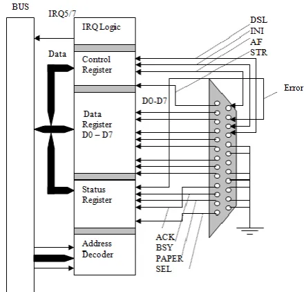
[image:1.595.322.544.542.753.2]The parallel port interface is one of the simplest and most straight forward circuits that is encountered in a PC. Fig. 1 illustrates a typical bi-directional port.
Fig. 1. Block diagram of a bi-directional parallel port
A Smart Microcomputer-Based Controlled
Device for Electrically Powered Gadgets
Sunny Orike Member, IAENG and Joseph Diema Enoch
A parallel port is composed of three separate registers, the data register, the status register, control register. Address bits A0 to A9 are decoded to determine which of the three registers are active. The use of I/OR (I/O Read) and I/OW (I/O write) lines determine whether signals on the data bus (D0 to D7) are being read from or written to the respective register[2]. When the port is ready to accept another character, handshaking line conditions will trigger an interrupt to request a new character. The heart of a parallel port is the data register. In older PCs, the data register could only be written to. But virtually all PCs since the release of 80386 systems provide data registers that can be read and written to (which makes the port bi-directional). To access a printer, the system CPU simply loads the port data register with the value to be passed. The bi-directional control register manages the behavior of the port, and affect the conditions under which new characters are requested from the CPU for example, the control register is typically setup to generate an interrupt whenever the printer is ready to accept another character. Finally, the status register is read to determine the printer’s status. The remainder is the port connector (a female 25pin subminiature D-type connector). C.Switches
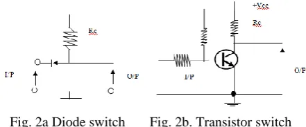
Any device for opening closing or directing an electrical circuit is called a switch. Switching may be automatic (without operator’s intervention), semi-automatic or manual (involving some degrees of operator’s intervention). There are various types switches, however all switches carry maximum current and voltage ratings; a small toggle switch might be rated at 150V and 5A. Relays are electrically operated switches in which a current flowing in a coil, or winding, is made to operate one or more contacts which can be used to open or close other electrical circuits. In the usual type; a coil pulls in an armature when sufficient coil current flows. Many varieties are available including “Latching” and “stepping” relays[3]; the latter provided the cornerstone for telephone switching stations, relays are available for DC or AC excitation, and coil voltages from 5 volts up to 110V are common “mercury wetted” and “reed” relays are intended for high speed (
1ms) applications, and giant relays intended to switch thousands of amps are used by power companies[3]. Many previous relay applications are now handled with transistor or FET switches, and devices known, as solid-state relays are now available to handle AC switching applications. The primary uses of relays are in remote switching ad high-voltage (or high current) switching. Because it is important to keep electronic circuit electrically isolated from the ac power line, relays are useful to switch ac power while keeping the control signals electrically isolated[3].Much previous relay applications as mentioned earlier are now handled by transistor and FET switches. Fig, 2 shows how diodes and transistors can be used as switches. If the input to the circuit in Fig. 2a is zero, the diode is forward biased current, flows easily and the output is approximately zero. If the input is 5V (or more), no diode current flows and the output is + 5V (or more). Hence the OFF - ON positions of the diode switch correspond to voltage level near zero and + 5V.
In the elementary transistor switch in Fig. 2b with a zero
input, the emitter junction is reverse biased by VB, the collector current is very small output voltage is high. A positive input and the output voltage is high. A positive input forward biases the emitter junction, a large collector current flows and the output is low. Again, the ON - OFF position of the transistors switch correspond to the high and low output, but the output is inverted.
Fig. 2a Diode switch Fig. 2b. Transistor switch
D.Power Supplies
[image:2.595.318.539.143.235.2]All electronic equipment needs to be energized by means of power supply. In the great majority of cases the power is delivered to the electronic circuit at a steady or fixed voltage[4]. The power source use for this work is a DC power supply from the mains starting with an AC voltage, a steady DC voltage is obtained by rectifying the AC voltage; then filtered to a DC level, and finally regulated to obtain a desired fixed DC voltage. Fig. 3 shows the functional block diagram of a regulated DC power supply. The regulation can be obtained using zener diodes or transistors or a combination of both to form a series or parallel regulators. However, IC voltage regulator units make design easy, reduce external circuit connections and offer better performance than even operational and profile regulators. Example of such IC voltage regulators are the 7806 and three-terminal +5V regulator and the 7912, a three-terminal +12V regulator, the ‘317, a three-terminal adjustable voltage regulator to mention but a few.
Fig. 3. Block diagram showing part of a power supply
E.Connectors
individual circuit cards. Alternatively edge connectors may be used with standard solder-lug terminations, particularly in a system with only a few cards.
Very frequently electronic instruments demand multi-wire cables and connectors. There are literally dozens of different kinds. The simplest example is a 3-wire line cord connector. Among the more popular are the excellent type D subminiature, the Winchester MRA series, the venerable MS type, and the flat ribbon-cable mass-termination connectors. Beware of connectors that cannot tolerate being dropped on the floor (the miniature hexagon connectors are classic) or that does not provide a secure locking mechanism.
III. THE DESIGN OF THE DEVICE INTERFACE Interface deals with the common boundary between independent system and modules, where communication takes place. In data communication, it means a share boundary between two related devices or components defined for the purpose of specifying the type of signal passing between them[5].
A.Input Design Considerations
Bringing signal in and out of a device for communication to take place between two related or unrelated devices depends on certain factors or standards. A microcomputer can be interfaced with other devices via the expansion slots or the existing PC ports.
Considering the cost, time, effort, and the kind of analysis and test involved in designing the device card and in programming the slot; we deemed it necessary to make use of the existing PC ports since it involves only programming it to achieve the desired purpose. Finally, for cable communications with high-speed peripherals, parallel transmission is generally better than serial which is an essential aspect to the design of the device.
B.PC Parallel Port
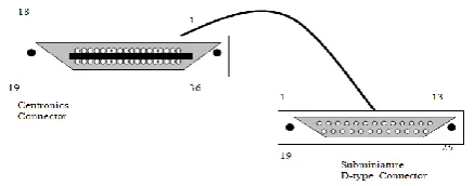
IBM and compatible PCs implement a parallel port as a 25-pin subminiature D- type female connector similar to the one in Fig. 4. The parallel connection at the printer uses a 36-pin centronics-type connector. The exact reasoning for this rather specialized connector is not clear because 11 pins of the centronics connector will remain unused. There are three types of signals to be concerned with in parallel connection data lines, control (or handshaking) lines, and ground lines.
[image:3.595.63.282.616.702.2]
Fig. 4. A typical parallel cable assembly
Data Lines: The data lines are the actual data carrying
conductors that carry information from the parallel port to the device (or other peripheral). There are eight data lines (D0 to D7) located on pin 2 through pin 9. To reduce the effect of signal nose on parallel cable, each data line is given
a corresponding data ground line (pin 18 to pin 25). Ground lines also provide a common electric reference between the computer and peripheral. The remainder of a parallel port is devoted to handshaking
Initialize: To ensure that the device starts in a known
initialized state, an initialize signal (INI on pin 31) tells the device to perform its internal initialization sequence. Initializing the device has the same effect as turning it OFF then turning it ON again.
Select: The SLCT signal on pin13 goes high if the printer
is selected for receiving data. SLCT is an active high logic signal. Logic 1 indicates that the device is on line and ready, while logic 0 indicates that the device is not ready to receive data.
Strobe: Once a computer has placed eight valid bits on
the parallel data lines, the device must be told that the data is ready. A strobe signal (STROBE on pin 1) is applied to the peripheral from the computer just after data is valid.
Acknowledge: The ACKNIG signals on pin 10, which,
where low, indicates that the data character has been accepted and the device is ready for the next character. Since the device is always ready under normal circumstance the ACKNIG is always low.
Busy: The busy signal on pin 11 is high if, for some
reason the device is not ready to receive a character (signals). In this work, the busy signal is always low since the device needs to receive continuous signal is be able to control the appliances.
Error: The ERROR signal on pin 32 goes low for a
variety of problem condition in the device. The error signal generated by the device tells the computer that trouble has occurred, but is not specific about the exact problem. A variety of problems can cause an error, depending on the particular peripheral and what it is capable of detecting. The error line uses active low logic so it is normally logic I until an error has occurred. An error signal can typically indicate “device not receiving electrical power from the mains”, “every low voltage level from mains” or “general device fault” error condition.
Port Operation: This describes a standard sequence of
events in a parallel port. The parallel data transfer begins by placing the device on line. Strobe and acknowledge must be logic 1, and busy must be logic 0. In this state, the peripheral can now accept a byte of data. When power supply is interrupted, the CPU polls the desired device port and checks its status register. If the port is ready, a byte is written to the data register, and passed to the peripheral. C.Output Design Consideration
The device needs to be connected to the home appliances and the computer if these appliances must be controlled and the status of the device port should be read by the computer. Amongst the connectors mentioned for bringing signals in and out of an instrument, routing signal and DC power around, between the versions parts of an instrument are the signal wire connectors shielded, cable connectors, multi-pin connectors and care edge connectors.
There are literally dozens of different kinds. The simplest is a 3-wire line cord connector each of the terminals for the home appliances. It contains screw that is used to screw the cables coming from the home appliances. Another way that this could be done is by using a socket outlet and, a socket plug. This will make the work tedious, and it is also not economical compared to the 3-wire line cord connector.
Among the more popular multi-pin connectors are the excellent types D-type subminiature and the centronics connector. The subminiature d-type connector is used by the PC parallel port (normally known as the printer port) and the centronics connector is used by the device to receive or send data from or to the PC respectively, for proper coordination and working conditions.
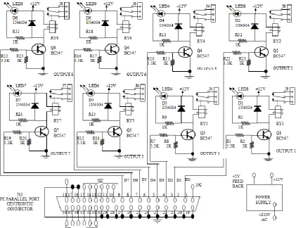
IV. THE DESIGN OF THE DEVICE
The circuit is basically a bunch of resistors, diodes, transistors and relays. The major components are the transistors and relay switch (about eight in number). The relay switch can switch load of about 220V AC at 10amps each. The relays and their control circuitry are attached into a multi-purpose board (vero board), which is soldered in such a way that the relay contacts are easily accessed. All the board needs to operate is a 12V DC power supply, a spare PC to control it and cables that will connect the appliances to the PC parallel port relay output connector. More so an AC input supply from the mains to the device and a software that will enable (drive) the device to control the home appliances based on the sequence of instructions it has been set to perform.
The computer controls the relay board via its parallel port. It is possible to have the computer perform double duty as a work computer and as a controller for the relay board, but it just easier if an old computer can be dedicated to drive the relay board. All the computer has to do is to output a hex-byte at the parallel port every so often, which is not a very hard work for any computer.
[image:4.595.366.498.169.250.2]The device is constructed in such a way that, it creates room for handshake between the computer and the relay board. Take for instance, if for any reason the mains supply is not received by the device (relay board), it generates an error message signal, which is sent to the PC parallel port. The software for the device reads this port and displays a critical error message to give the user an idea of the status of the device. Fig. 5 shows a schematic representation of the device.
Fig. 5. Block diagram of the PC parallel port relay
A.Transistor Switches
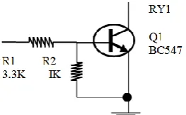
[image:4.595.330.531.548.694.2]As already mentioned, eight transistors switches are required for this work. The eight transistors receive the electrical signal sent through the PC parallel port, which is compactable with TTI signal levels. These electrical currents or voltages, enables the transistors to energize or de-energize the relays switches connected to them. Fig. 6 shows the circuit diagram representing the transistor switch.
Fig. 6. NPN–transistor switch
The resistor R1 is used for biasing the transistor and R2 is used to further protecting the transistor from excess current flowing through its base. The transistor switch was chosen because of the following reasons:
(i) It enables very high switching, typically in a small fraction of microseconds.
(ii) It is cheap to construct
(iii) It makes the design less complex.
B.Relay Switch
To turn 110V, 220V, or 440V AC device ON and OFF under microprocessor or microcomputer control, relays are used. The control circuitry for the relay is electrically isolated from the actual switch[6]. This is very important, because if the 220V AC gets shorted to the Vcc line of a microcomputer, it usually takes most of the microcomputer ICs. Fig. 7 shows a block diagram of the circuitry in the device and how it is connected from a PC parallel port pin to a 3-wire line cord connector, for power delivery to one to the home appliances.
[image:4.595.59.291.631.769.2]transistor and pulls the required current through the diode, D1. A 12V power supply must be included because the relay switch needs it for its operation. The resistor R3 is used to protect the LED from excessive current, and the diode connected across the relay is to prevent excess current from flowing through the transistor since it is connected to an inductive load. The light from the LED indicates that an output port of the device is currently being activated to supply power to the corresponding household equipment. The solid state relay have the advantages that they produce less EMI (electromagnetic interface) they have no mechanical contacts to arc, and they are easily driven from microcomputer ports.
C.Power Supply
The relay board needs to be operated by a 12V DC power supply, regulated at +5V and +12V using the 7806 and 7812 IC regulator[4]. The +volts regulated supply serves as a feedback signal to an input port pin (i.e., computer parallel port). This is to indicate whenever the device is adequately connected to the main AC supply or when there is a general power failure or general device failure. This enables the PC to send data or display a critical error message when necessary. The 12V regulated power supply is to enable the relay switch to be operated when it is being energized by the transistor switch. It also supplies enough current for the corresponding LED. The 7806 and 7812 ICs were used in this project because of the following reasons:
(i) They require much reduced resign calculation (ii) They require very few external components (iii) They are effective 5V and 12V regulators (iv) They are cheap to construct.
Finally the DC regulated power supply was chosen due to the fact that the essential role performed by the device is based on the main AC power supply.
D.Design Circuitry
The different building blocks and assembly are described here. The system block diagram is shown in Fig. 8. A HIGH signal from the PC’s parallel port turns on a transistor that energizes a relay, causing the relay contacts to switch in the diagram, two sets of relay contacts control 220V AC to power a lamp and the fan, another set of contacts close the thermostat’s circuit, thus providing heat for the building. Each relay operates independent of the other. The relay board contains eight identical channels, each containing a relay whose contacts are rated at 10A. The eight channels are controlled by pins 2-9 of the input centronics connector. A centronics connector is used so that the relay board can be connected to a computer with a standard printer cable.
Fig. 8 illustrates the basic operation of the PC’s parallel port relay. The PC send a trigger signal to the appropriate relay, closing the relays contacts, which energizes the device connected to it.
V. CONSTRUCTION OF THE DEVICE
The relay circuit was easy to build, especially with the use of a PC board. The circuit is simple enough to use point to point wire in its assembling. First, we installed all the resistors, followed by the diodes, LEDs, transistor. Finally, the lacks and relays; including a check on the polarization of
the relays of diodes. Carefulness was employed when soldering, especially when soldering the pins of the centronics connector (JA).
A.Setting up of the PC Relay Board
Finally the different building blocks was designed and assembled together. Let us now take a look at the construction of the PC parallel port relay board from breadboard stage to casing. First of all, the components used were tested to ensure that they are good and have values capable of performing the required job. The resistance of each resistor was measured directly using digital multi-meter, while capacitors were tested for charge /discharge characteristics using a digital multi-meter too. Again, a digital meter was used to text transistor by forward biasing their emitter-base junction and diverse biasing their base collector junction. The diodes were checked again by forward and reverse biasing the NPN junction on each diode. The terminals of the coil in the relay were supplied with a 12V and a 5V supply. The sound heard by the “make” contact proofs the relay to be good. The different blocks where connected into the breadboard and the output tested using voltage measurements to confirm if that particular stage is behaving as expected before the next stage was compiled to it. When the entire circuit was finally put on the board and found working as expected, all the components were transferred onto a piece of Vero board and soldered. The size of the Vero board is 260 x 100mm. The casing of size 300 x 150 x 100mm is made of loud which also contains all the design components. Pillars ensuring that two stops are not shorted or no used copper strip is broken.
Originally, in the project design, we intended using 470052 resistor for RI (likewise for resistor R4, R7, R10, RB, R16 and RR2 in the other channels). When it came time to test the board connected to a parallel port, the port could not turn the relays (actually the transistors) ON and OFF. It turned out that the resistance was too high, at least for the PC port being used. A better value for the resistor is 330000, but most values between 220052 and 470052 would work. Basically, it is recommended to use the highest resistance that will let the circuit work while keeping transistor current as low as possible.
Recall that the relays require a 12V DC source to operate. That source must be provided by the builder. Actually the relay power source voltage is not too critical anything between 9 and 15V should be enough.
Fig. 8. Block Diagram of the Design Smart Device
VI. CONCLUSION
Haven gone through this study, it is clear that the aim of this project which is to design and construct a microcomputer based smart system for house hold equipment have been achieved. The device was able to control appliances in the home automatically according to the specified instructions given to it.
You will find that the PC parallel relay was a very convenient device to have around the house. With a bit of imagination, you should be able to automate neatly any kind of electrical device. Nearly anything is possible with the PC parallel port relay and you may be the one on your block to have a house of the future which will be of high demand in developing countries.
REFERENCES
[1] S. Mueller (n.d.). Upgrading and Repairing PCs (22nd Edition). Retrieved from https://www.amazon.com/Upgrading-Repairing-22nd-Scott-Mueller/dp/0789756102, February 25, 2019.
[2] N. M. Morris (1981). Microprocessor and Microcomputer Technology. Macmillan Publishers Limited, Palgrave, London. DOI 10.1007/978-1-349-16651-0, retrieved from https://link.springer.com/ content/pdf/bfm%3A978-1-349-16651-0%2F1.pdf, March 1, 2019.
[3] S. Elango, E. Dhinesh , K. Santhosh kumar, S. Sethupathi, and S. Vivek, “Digital Relay Protection of Generator Transformer in Thermal Power Station using Microcontroller,” International Journal of Intellectual Advancements and Research in Engineering
Computations, vol. 6, no. 2, 2018, pp. 2142-2145.
[4] G. H. Olsen, Electronics, A General Introduction for the Non-Specialist "Power Supplies", chapter 7, pp. 157, retrieved from https://books.google.com.ng/books?isbn=1489965351, March 1, 2019.
[5] D. Longley, M. Shain. Macmillan Dictionary of Information Technology "Chapter 9 I", Springer Nature. DOI
10.1007/978-1-349-17801-8 retrieved from
https://www.palgrave.com/gp/book/9781349178018, March 1, 2019. [6] Circuit Today (August 14, 2018). Working of Relays. Retrieved from