BIM-GIS modelling in support of emergency
response applications
P. Boguslawski
1, L. Mahdjoubi
1, V. Zverovich
1,
F. Fadli
2& H. Barki
21Faculty of Environment and Technology,
University of the West of England, UK 2Qatar University, Qatar
Abstract
Building Information Modelling (BIM) provides a detailed 3D geometrical model with rich semantics that go beyond the standard Computer-Aided Design approach. In contrast, Geography Information Science (GIS) offers powerful spatial analytical tools. This paper seeks to propose and innovative the research approach, integrating some aspects of BIM and advanced GIS analysis. This may advance beyond state-of-the-art emergency response applications. The advocated research approach evolves beyond the simplistic 3D indoor scene representation and instead proposes to automate the generation of navigable models depicting complex interiors readily available in the building industry area, which adopts BIM as the main tool for design and information exchange.
Keywords: BIM, GIS, gbXML, emergency response, data structures.
1
Introduction
Building Information Modelling (BIM) became a mature and widely accepted modelling process in the building industry area [1]. A 3D geometrical model is a basis for information representation and sharing. Details provided in the model are usually not available in Geography Information Systems.
examination of spatial behaviour and accessibility in building environments. 3D network models are powerful in depicting pedestrian access and movement within buildings that can be modelled as a network of walkway sections and connections [3]. This network of walkways could potentially be disrupted by an emergency such as an explosion, fire or obstruction, as a result of a partial destruction of the building.
This paper proposes an innovative approach integrating some BIM and advanced GIS analysis leading to an improved 3D analytical model for emergency response. Most research, so far, has focused on simplistic indoor scene representation, usually based on 2D floor plans, and with a navigable network often manually reconstructed, where only doors are used for human movement [3, 4]. In this study, beyond state of the art approach is proposed, where other alternative routes, in addition to using doors, are considered for indoor navigations, e.g. walls or partitions can be drilled in order to get access to adjacent rooms or safer places. Thus, information about material used for construction is critical. This can also be used in other applications based on the same model, for example, in fire spread simulation to calculate fire resistance.
The proposed BIM and GIS model integration for emergency response is based on using the following: Green Building XML (gbXML) and Industry Foundation Classes (IFC) as data input, and GIS analysis methods and data structure, more precisely – the dual half-edge (DHE) [5].
1.1 Research approach blending BIM and GIS
BIM is a fast developing field and many countries (e.g. the United Kingdom and Singapore) and institutions decided to introduce BIM as a standard for information exchange and stakeholders collaborative work on public building design and construction. This gives impetus for developing new tools which are getting mature and are quickly adapted. At the same time, the need for more sophisticated analysis tools arises because different stakeholders use BIM for various applications. One of the fields converging on BIM is GIS which can offer advanced tools for spatial analysis [6].
One of the advantages of BIM is a good quality 3D model which is a core element. On the other hand GIS requires a spatial model for its analysis methods. BIM and GIS building models are similar, but at the same time there are differences to be levelled down in order to create a “common language” for communication and information exchange [7]. In recent developments researchers propose conversion of BIM models into GIS formats, e.g. IFC to CityGML [8, 9], or new unified models [10]. These solutions work for specific applications and take a big step towards the common language; however, there is still work to be done for developing widely accepted standards.
(e.g. office room, storage room, fire exit, etc.): gbXML is an open schema which helps simplifying and transferring 3D building models to engineering analysis applications [11].
In simple terms, a typical gbXML model consists of two parts: spaces and surfaces. A space is a closed shells (volume) representing a room geometry. Shells are separate objects without information on relationship to other cells; openings (e.g. windows, doors) are not included. A surface is a simplified abstraction of the wall which divides adjacent spaces and includes links to these spaces. Also, openings, represented as separate surfaces, are embedded into the wall surface. These two parts, spaces and surfaces, are suited not only for visualisation but they are also sufficient for building topology reconstruction, because information about relationship between adjacent rooms is included.
It should be noted that the process of simplification to gbXML introduces some inconsistences like missing faces or overlapping volumes in the surface part which may be acceptable for engineering analysis. However, some corrections are required in applications where spatial relations must be unambiguously reflected in a model. The problem of consistency and validation was investigated by several researchers [12, 13]. The format specification requires a room to be a closed shell, while it does not impose such a restriction on the shell closure in case of surfaces (abstract walls) representing walls. A surface, usually computed as a flat face at the centre of the original wall, may overlap with neighbour surfaces. Also, it might happen that surfaces do not form closed shells as some surfaces may be missing in the model. Thus, a model improvement is necessary in order to use the DHE. In order to get a good quality gbXML model some rules should be applied to the original BIM model during development [14], e.g. rooms should be assigned to all areas; room or wall overlapping is not allowed; floors should be defined for all areas; room boundaries should be defined, etc.
However, good quality 3D models are not easily available. Currently, CityGML is the widely used data model in GIS to represent urban models [16]. A model can be stored in a different Level of Details (LoD): from LoD0 to LoD4, where the lowest level includes digital terrain model with optional building footprints, while the highest level is able to represent detailed building interiors including furniture and installations. As a matter of fact, most of the available models do not include LoD4, because it is too detailed and storage space consuming: the building coarse geometry often accompanied by façade textures and predefined roof type, street network, and other appearance and thematic objects is sufficient for visualization and spatial analysis in the outdoor environment. Therefore, indoor models are often reconstructed, in many cases manually, from architectural plans, so that the model is formed from a series of 2D layers connected by entrance nodes. These models are usually suited for specific applications and stored in an in-house format which does not conform to any standard. It makes such models difficult to exchange or impossible to use when the format specification is not available.
Because of the lack of 3D models GIS researchers adopt models from other fields: one of them is BIM which can offer good quality models [17]. It should be noted that the BIM model only describes a building structure, while many thematic objects, important from the viewpoint of GIS, are not included, e.g. street network, vegetation, water objects, city furniture, etc.
1.2 Advances in emergency response
Most of research on emergency response in a building environment is focused on rescue and evacuation, which are related to path finding and indoor navigation [3, 4, 15, 18, 19]. Different researchers focus on different aspects of evacuation: least risk paths [19], path simplicity [20], navigable network improvement [3, 15], more detailed routes [4], and human behaviour [21].
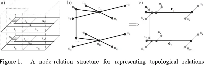
Whatever evacuation algorithms are used in the aforementioned research, there is always a spatial model in the background (see Figure 1a). A building structure is represented as a logical network, where its nodes represent rooms, including corridors and other navigable areas; and edges represent navigable connections between adjacent rooms (see Figure 1b). The network can be further improved into a geometric network in order to reflect real navigation routes and more precise geometric properties e.g. distance between nodes (see Figure 1c) [3]. This representation allows applying graph algorithms such as Dijkstra’s or A* algorithms for shortest path finding in evacuation planning.
Figure 1: A node-relation structure for representing topological relations among objects in 3D space: a) 3D spatial objects; b) logical network; c) geometric network [3].
Most of the 3D navigation models represent buildings with a simple, often regular, structure which is not sufficient for complex interiors. Liu and Zlatanova [18] proposed a new concept of automatic navigable network generation based on the geometry and semantics of a building. However, their method requires, as many other methods, a valid spatial model as an input data set, where consistency between the geometry and topology is preserved.
2
Methodology and results
One of the objectives of this research is to propose a step change in emergency response intelligence to assist emergency response personnel to better prepare, predict and deal with emergencies in buildings. This entails the development of an intelligent innovative approach, involving the reconstruction of an indoor navigable network from a BIM model. The network used by path finding algorithms, which is an essential element in emergency response applications. The research workflow is illustrated in Figure 2.
gbXML is the main data format used as an input. We consider the gbXML format as a simplified model: a detailed geometry is simplified to a level sufficient to preserve adjacency relationship between rooms which is essential in this research. The model is significantly smaller in terms of storage space compared to a full model, for example, stored in the IFC format.
Information about room volumes and wall surfaces including openings (i.e. doors and windows) is accompanied by attributes such as: room name, room function, etc. Openings are used for conventional navigation and egress routes computation. However, other alternative routes are also considered in case of direct hazard, e.g. walls or partitions can be drilled in order to get access to adjacent rooms. This requires additional information about construction material which can be obtained from the original model. The external links in gbXML allows to look up required parameters if the original model is available, e.g. the IFC model.
Figure 2: Research workflow (dashed lines represent optional steps if the original IFC model is available).
developed DHE [5]. In this research, DHE was developed as the model geometry, and the navigable network can be stored simultaneously without an extra cost. This is not available in case of the aforementioned data structures.
A simple model of a building stored in the Autodesk Revit format was exported to the gbXML model and reconstructed using the DHE data structure (see Figure 3a). Each room is represented as a cell with an associated dual node unambiguously representing this cell. Adjacent cells are connected by dual edges into a cell complex and each dual edge is bounded by nodes representing adjacent cells.
A door between two rooms is represented as a zero-volume cell with an associated unique node. Thus, there are two dual edges connecting the first room node to the door node and the door node to the second room node. The same idea is applied in case of a door between an internal room and an external space. The latter is represented as a cell or a set of connected cells if it was partitioned. The complete graph of indoor connections is shown in Figure 3b.
representation of spatial relations among objects. Thus, missing faces must be generated and cell overlapping removed. This is vital when external models are utilized and the original BIM model is not available.
Figure 3: Simple model reconstructed using the DHE data structure: a) structure of a building with doors and windows includes one selected room (grey cell); windows are connected to wall boundaries by bridge edges (dotted line); b) graph of connections between rooms.
The model of a building after the “healing” process is shown in Figure 4, where missing faces generation was only required while no room overlapping was found. However, overlapping was faced in other tested models, which are not shown in this paper.
[image:7.442.110.327.338.551.2]The “healing” process is necessary to automatically reconstruct both the navigable network and the valid primal-dual representation. For instance, missing faces between adjacent rooms (see Figure 5a) introduce ambiguity in cell identification, because the cells would be merged into one volume (see Figure 5b) and represented by one node (see Figure 5c). To fix this problem, a new face is introduced (see Figure 5d) which splits the volume into two parts (see Figure 5e) represented by two unique nodes (see Figure 5f).
Figure 5: Invalid model with a missing face: a) two cells sharing a face (grey) with a missing face (white); b) two cells form one volume; c) two cells are represented by one node; d) model after the “healing” process; e) two cells are separated and they form two volumes; f) two cells are represented by two nodes.
Figure 6: Invalid model with overlapping cells: a) two cells are represented by two dual nodes but the grey shared volume is not unambiguously associated with any of the cells; b) shared volume may be subtracted from one cell; c) shared volume may be subtracted from two cells and form a separate cell.
The above problems with missing faces and cell overlapping are described using simple examples. However, the situation may be more complex if we consider several non-planar adjacent faces that are missing or several cells sharing the same or part of a volume. The DHE is able to deal with non-planar faces and arbitrary shapes. Thus, the only problem to solve is to create a valid cell complex without cell overlapping or gaps between adjacent cells.
Figure 7: Egress route (black) calculated for a selected room starting at “X” to the closest exit (dark grey cell).
3
Conclusions
In this paper, research development on BIM – GIS integration was proposed for egress route calculation. The indoor building model geometry can be easily retrieved from the gbXML format but it may need some pre-processing to validate the model. The DHE data structure used for 3D model reconstruction includes the dual graph of connection between rooms which is constructed automatically when the geometry of the model is created. The graph can be used directly by graph algorithms to find egress routes from buildings.
Future work includes development of functions to “heal” invalid models and reconstruct a navigable network for an arbitrary BIM model. In addition, material of walls will be considered in implementation of algorithms for alternative egress route calculation.
Acknowledgement
This research/publication was made possible by a National Priority Research Program NPRP award [NPRP-06-1208-2-492] from the Qatar National Research Fund (a member of The Qatar Foundation). The statements made herein are solely the responsibility of the author(s).
References
[1] Przybyla, J., The next frontier for BIM: interoperability with GIS. Journal of Building Information Modelling, pp. 14-18, 2010.
[3] Kwan, M.-P. & Lee, J., Emergency response after 9/11: the potential of real-time 3D GIS for quick emergency response in micro-spatial environments. Computers, Environment and Urban Systems, 29, pp. 93-113, 2005. [4] Liu, L. & Zlatanova, S., A “door-to-door” path-finding approach for indoor
navigation. Gi4DM 2011: GeoInformation for Disaster Management, 2011. [5] Boguslawski, P., Modelling and Analysing 3D Building Interiors with the Dual Half-Edge Data Structure, Faculty of Advanced Technology, University of Glamorgan: Pontypridd, Wales, UK, p. 134, 2011.
[6] Ball, M., With new tools for modeling and measuring impacts of plans and designs, are GIS and BIM converging? Sensors & Systems, Online: www.sensorsandsystems.com/dialog/perspectives/35458-with-new-tools- for-modeling-and-measuring-impacts-of-plans-and-designs-are-gis-and-bim-converging.html, 2015.
[7] Wood, T., A BIM/GIS Roadmap, GISProfessional, pp. 14-17, 2013. [8] Isikdag, U. & Zlatanova, S., Towards Defining a Framework for Automatic
Generation of Buildings in CityGML Using Building Information Models, 3D Geo-Information Sciences, ed. J. Lee & S. Zlatanova, Springer Berlin Heidelberg, pp. 79-96, 2009.
[9] Laat, R. & Berlo, L., Integration of BIM and GIS: The Development of the CityGML GeoBIM Extension, Advances in 3D Geo-Information Sciences, ed. T.H. Kolbe, G. König & C. Nagel, Springer Berlin Heidelberg, pp. 211-225, 2011.
[10] El-Mekawy, M., Östman, A. & Hijazi, I., A Unified Building Model for 3D Urban GIS. ISPRS International Journal of Geo-Information, 1(2), pp. 120-145, 2012.
[11] Mapentzidis, G. & Raslan, R., A Comparative Analysis of BIM-integrated and Traditional Energy Modelling Methods for Building Energy Retrofit, Building Simulation and Optimization, UCL: London, UK, 2014.
[12] Horna, S., Meneveaux, D. Damiand, G. & Bertrand, Y, Consistency constraints and 3D building reconstruction. Computer-Aided Design, 41(1), pp. 13-27, 2009.
[13] Wagner, D., Wewetzer, M., Bogdahn, J., Alam, N., Pries, M. & Coors, V., Geometric-Semantical Consistency Validation of CityGML Models, Progress and New Trends in 3D Geoinformation Sciences, ed. J. Pouliot, D., Sylvie, H., Frédéric, Z., Alborz, Springer Berlin Heidelberg, pp. 171-192, 2013.
[14] EDSL, EDSL Guide for Revit gbXML Files: http://edsl.myzen.co.uk/ downloads/misc/EDSL%20Revit%20gbXML%20Guide%20v1.23.pdf, 2014.
[15] Lee, J., A Three-Dimensional Navigable Data Model to Support Emergency Response in Microspatial Built-Environments. Annals of the Association of American Geographers, 97(3), pp. 512-529, 2007.
[17] Rueppel, U. & Stuebbe, K.M., BIM-Based Indoor-Emergency-Navigation-System for Complex Buildings. Tsinghua Science & Technology, 13, Supplement 1(0), pp. 362-367, 2008.
[18] Liu, L. & Zlatanova, S., Towards a 3D network model for indoor navigation, Urban and Regional Data Management, ed. Zlatanova, Ledoux, Fendel & Rumor, CRCpress/Taylor and Francis Group: London, pp. 79-92, 2012. [19] Vanclooster, A., De Maeyer, P., Fack, V. &Van de Weghe, N., Calculating
Least Risk Paths in 3D Indoor Space, Innovations in 3D Geo-Information Sciences, ed. U. Isikdag, Springer International Publishing, pp. 13-31, 2014. [20] Duckham, M. & Kulik, L., “Simplest” Paths: Automated Route Selection for Navigation, Spatial Information Theory, Foundations of Geographic Information Science, ed. W. Kuhn, M. Worboys & S. Timpf, Editors, Springer Berlin Heidelberg, pp. 169-185, 2003.
[21] Choi, J. & Lee, J., 3D Geo-Network for Agent-based Building Evacuation Simulation, 3D Geo-Information Sciences, ed. J. Lee & S. Zlatanova, Springer, pp. 283-299, 2009.
[22] Weiler, K., The Radial Edge data structure: A topological representation for non-manifold geometric boundary modeling, Geometric Modeling for CAD Applications, ed. J. Encarnacao, L., M. Wozny, J. & H. McLaughlin, W., Elsevier Science (North-Holland): Amsterdam, pp. 3-36, 1988.