Research Journal
Volume 12, No. 2, June 2018, pages 260–265
DOI: 10.12913/22998624/92459 Research Article
LOCKING THE MOVEMENT OF PERSONS ON THE BRIDGE CRANE
Jozef Kuľka1, Martin Mantič1, Melichar Kopas1, Eva Faltinová1
1 Technical University of Kosice, Faculty of Mechanical Engineering, Department of Design, Automotive and Transport Engineeing, Letna 9, 042 00 Kosice, Slovak Republic, e-mail: [email protected], martin.mantic@ tuke.sk, [email protected], [email protected]
ABSTRACT
This article describes the design of a horizontal rope system for increasing the safety of
work and movement on a specific device operating in height. This system is designed
to be installed on a conventional existing crane footbridge or crane track structure and this system enables a free pass along the rope, without unclamp of spring hook on
prolongation rope. The calculation was made by non-linear dynamic FEM analysis.
Keywords: rope, safety, non-linear dynamic FEM analysis.
INTRODUCTION
The basic condition of modern approaches in the phase of projection and design, as well as during current operation, repairs, maintenance and recycling, is to take safety requirements into consideration. However, there are still aged machines in operation and machinery that were designed and produced more than 30 years ago. They are suitable enough from the durability and functionality point of view, but they are no longer reliable from the aspect of labour and health pro-tection with regard to the new safety rules, taking conditions for safe movement of workers on their structure into consideration. Every user of such a machine has to ensure correction of faults.
One of examples of the above-mentioned problems is operation and maintenance of over-head travelling cranes working on open-air weather conditions. Entrance into the crane-op-erator’s cab as well as maintenance during win-ter period is especially dangerous. Therefore it is necessary to apply a belaying system in a given working area.
The publications [1, 2] deal with the steel wire ropes taking the general principles of their operation and safety into consideration. Possible causes of rope damage are described in the works
[3÷6]. Similarly, the analysis of the stress state and operational loading as well as failure analysis of the steel wire ropes are published for example in the articles [7÷10]. There are desscribed in the papers [11, 12, 13] the mathematical and geomet-ric models developed for computer simulation of the ropes. The dynamic non-linear simulations that are performed using the Finite Element Meth-ods (FEM) are presented in the articles [14÷18].
TECHNICAL DESCRIPTION OF THE
PROPOSED SOLUTION
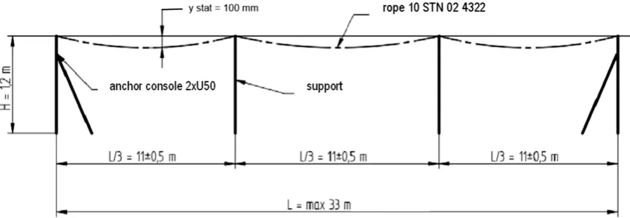
Horizontal belaying system (HBS) was de-signed for overhead cranes with maximum span of crane bridge 33 m. As a permitted load, which is acting on the field between two supports, is considered the weight of mass m = 200 kg, i.e. the weight value is G = 200 x 9,81 = 1962 N.
There are various arranged walkways on the bridge cranes; they have variable widths and dif-ferent obstacles, etc. Therefore, the HBS is de-signed in such way that the belaying rope is sup-ported with supporting members (supporting bars) in every third of its length (approx. 11 ± 0,5 m), in order to eliminate free deflection due to own mass of the rope, without a necessity of very high ten-sioning force. Seating of the belaying rope on the
supporting bars enables a free pass along this rope, without unclamp of spring hook on prolongation rope (the prolongation rope is a dumper of falling). The anchor high of rope above the walkway floors is 1,2 m, so that the theoretical axis of rope is high-er than it is situated an upphigh-er edge of railing (1,12 m). The suggested system can be seen in Figure 1. In the function of the belaying rope a standard six-strand crane wire rope with 114 wires accord-ing to the STN 02 4322 or an EN/DIN equivalent can be used. Anchor consoles and vertical sup-ports are made from the sections 2 x U50.
CALCULATION OF ROPE FOR THE HBS
Calculation process consists in determination of anchor forces and deformation characteristics of the HBS by means of a non-linear dynamic FEM-analysis. There was used the COSMOS/M software from the company SRAC, USA.
Input parameters:
• Rope Φ 10 mm (114 wires):
• A = 35,57 mm2 - cross-section area of the
rope,
• m = 0,31 kg.m-1 - mass of the rope,
• E = 570 000 ÷ 680 000 MPa - rope modulus of elasticity, (it is considered the Emax value - i.e. more unfavourable impact),
• L = 33 m - span of the rope,
• l = L/3 = 11 m - vertical supporting of the rope,
• F0 = 1000 N - initial pre-stressing of the rope. Load:
• G = 200 kg - weight of the load. Prolongation rope:
• G1 = 2 kg,
• lz = 600 mm - length of the prolongation rope,
• E1 = 55 000 ÷ 68 000 MPa - modulus of elas-ticity of the prolongation rope (hanger with spring hook).
Calculation model:
• For simulation of the ropes elements TRUSS2D were applied. The loads are simu-lated with mass element MASS and eventual short free-fall with tension of prolongation rope is simulated with a contact element GAP. The non-linear calculation was performed in two steps:
• 1st step - due to acceleration of gravity - the
shape of rope is a catenary depending of pre-stressing and parameters of supporting, • 2nd step - next, due to acceleration of gravity,
begins a free-fall of the load till to the mo-ment of final rope tension state and thus the whole system will be damped.
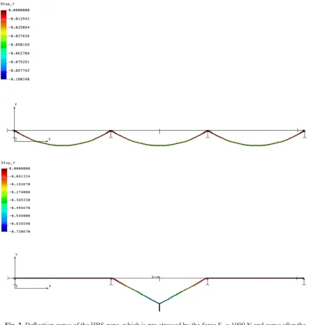
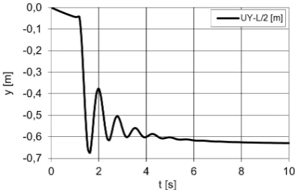
There are presented calculation results, for the above-mentioned input parameters, in the follow-ing graphs and tables. The Figue 2 demonstrates a deflection curve of the HBS rope due to own rope mass and after fallen of load. Next graphs, on the Figure 3 and 4, show a time behaviour of anchor forces in the rope anchorage points and in the points of supporting bars as well as a time behaviour of rope deflection in the point of falling load G (in the middle of HBS span).
In Table 1 and Table 2 there are maximum values of calculated forces and deflection that are illustrated in the graphs.
From the Table 3 it is evident that during mounting of the HBS-rope it is necessary to cre-ate such a value of the tension force in order the rope deflection, on the approx. 13 m span, will not be greater than 40 mm. The required pre-stressing force should be F0 = 1000 N.
Fig. 2. Deflection curve of the HBS-rope, which is pre-stressed by the force F0 = 1000 N and curve after the
falling of load
Fig. 3. Time behaviour of reactions in the rope anchor point and vertical reaction in the suspension point of the
STRENGTH CONTROL OF ANCHOR
CONSOLE
The calculation model of anchor console is on the Figure 5. Internal forces and normal stresses were calculated by means of the COSMOS/M software, based on static analysis for maximum values of dynamic effects that were specified by means of the beam elements BEAM3D.
Impacts of the applied force in the console are presented in Figure 5 (according to orientation of coordinates):
• Fx = 10 kN - horizontal force from the HBS-rope,
• Fy = -3 kN - vertical force in the support of the HBS,
• Fz = -1,5 kN - transversal force occurring in such situation when the falling was in direc-tion of inclined plane with angle 30º.
There are also bending moments in the con-sole components situated in the own plane of the console and in the normal plane, illustrated on the Figure 5.
In Table 4 calculated stresses in individual components of anchor console are given, where: • σt,d - is axial tension or push loading, • σy - is bending loading in the xy-plane, • σz - is bending loading in the normal plane to
the xy-plane,
• σmin, σmax - is resulting loading calculated as Σmin, max = σt,d, ± σy ± σz.
From Table 4 it is evident that the load capaci-ty of anchor console, which is made from steel 11 373 with strength value R = 210 MPa, is suitable.
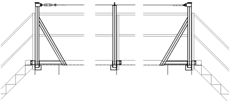
In Figure 6 an example of application of the HBS on the bridge crane walkway is presented. Fig. 4. Time behaviour of the HBS-rope deflection in
the middle of the span
Table 1. Maximum values of reactions in the anchor points of the HBS-rope
Knots 1, 67
RX [N] RY [N] R [N]
Max. 9418,3 23,6 9418,3
Table 2. Maximum values of vertical reactions in sup-porting points of the HBS-rope
Knots 23, 45 RY [N]
Max. 2669,4
Table 3. Maximum values of static and dynamic de-flection of the HBS-rope
Knot 34 (L/2) y [mm]
Max. stat. - 43
Max. dyn. - 674
Consoles together with rope are fixed to the wall of bridge and to the construction of railing. The rope is pre-stressed with tensioning screw.
CONCLUSION
In this article we demonstrated, how it is possible to increase labour safety on specific machinery, which is situated in the height, by means of a simple design solution, using com-mon construction materials (rolled shapes,
rope, rope clamps, rope socket eyes, tension-ing screw).
Currently, safety at work represents one of the main priorities of all manufacturing enterprises. The presented solution offers one of the options to increase safety at the same time meeting leg-islative requirements. This solution has already been successfully applied on a concrete type of bridge crane and by analogy have been resolved cases on a similar devices.
Table 4. Calculated values of stresses in components of the anchor console
σt,d [MPa] σy [MPa] σz [MPa] σmin [MPa] σmax [MPa]
EL 1
1 17,9 -51,8 -6,3 -40,2 75,9
2 17,9 -50,5 -4,7 -37,3 73,0
EL 3
4 17,9 -30,5 20,1 -32,7 68,4
5 17,9 -10,6 44,8 -37,5 73,2
EL 4
5 -2,5 -18,3 90,5 106,3 -111,3
6 -2,5 0,0 0,0 -2,5 -2,5
EL 5
7 -0,5 -10,9 137,0 147,4 -148,5
1 -0,5 -4,3 38,4 42,2 -43,3
EL 6
3 -22,2 62,6 12,9 53,2 -97,7
8 -22,2 33,8 -16,4 28,0 -72,4
EL 7
8 -22,2 33,8 -16,4 28,0 -72,4
5 -22,2 5,0 -45,7 28,5 -72,9
ACKNOWLEDGEMENTS
This article was elaborated in the framework of the Grant Project VEGA 1/0110/18.
REFERENCES
1. Boroška J., Hulín J. and Lesňák O. Oceľové laná. Alfa Bratislava, 1982.
2. Boroška J. Činitele ovplyvňujúce životnosť a bezpečnosť prevádzky oceľových lán. In: Výskum, výroba a použitie oceľových lán. KLaVS, Vysoké Tatry - Podbanské 2000, pp. 15-21.
3. Molnár V., Fedorko G., Stehlíková B. and Michal-ik P. Statistical Comparison of Rope Strands by ANOVA Test and Kruskal Walis Test. Tech. Tech-nol. Educ. Manag., 6, 2011, 1121-1126.
4. Torkar M and Arzenek B. Failure of crane wire rope. Eng. Fail. Anal., 9, 2002, 227-233.
5. Costello G. A. Mechanics of wire rope. Wire J. Int. 36, 2003, 56-63.
6. Chaplin C. R. Failure mechanisms in wire ropes. Engineering Failure Analysis 2, 1995, 45-57. 7. Peterka P., Krešák J., Kropuch S., Fedorko G.,
Molnar V. and Vojtko M. Failure analysis of hoisting steel wire rope. Eng. Fail. Anal., 45, 2014, 96-105.
8. Torkar M. and Arzenšek B. Failure of crane wire rope. Eng. Fail. Anal., 9(2), 2002, 227-233. 9. Giglio M. and Manes A. Life prediction of a wire
rope subjected to axial and bending loads. Eng. Fail. Anal. 12(4), 2005, 549-568.
10. Erdem Imrak C. and Erdönmez C. On the problem of wire rope model generation with axial loading. Math. Comput. Appl., 15(2), 2010, 259-268. 11. Stanova E., Fedorko G., Fabian M. and Kmet S.
Computer modelling of wire strands and ropes Part I: Theory and computer implementation. Adv. Eng. Softw. 42, 2011, 305-315.
12. Molnár V., Fedorko G., Krešák J., Peterka P. and Fabianová J. The influence of corrosion on the life
of steel ropes and prediction of their decommis -sioning. Eng. Fail. Anal. 74, 2017, 119-132. 13. Stolle C.S. and Reid J.D. Development of a wire
rope model for cable guardrail simulation. Int. J. Crashworthiness 16(3), 2011, 331-341.
14. Nawrocki A. and Labrosse M. A finite element model for simple straight wire rope strands. Com-put. Struct. 77(4), 2000, 345-359.
15. Imanishi E., Nanjo T. and Kobayashi T. Dynamic simulation of wire rope with contact. J. Mech. Sci. Technol. 23(4), 2009, 1083-1088.
16. Páczelt I. and Beleznai R. Nonlinear contact-theo-ry for analysis of wire rope strand using high-order approximation in the FEM. Computers and Struc-tures 89(11-12), 2011, 1004-1025.
17. Rudawska, A. and Debski, H. Experimental and
numerical analysis of adhesively bonded alumin -ium alloy sheets joints. Eksploat. I Niezawodn. - Maint. Reliab. 1, 2011, 4-10.