IJPCDR
ORIGINAL RESEARCH
Finite Element Analysis of Compressive Stress Pattern in
Implant-tooth Supported Fixed Partial Denture: An
In Vitro
Study
Srinivasa Gowda1, Lalit Kumar2, H S Indrakumar3, Komal Sehgal4, Rucha Kashyap5, Virender Kumar6, Dilip Daniel Quadras7
ABSTRACT
Aim: The aim of this study was to evaluate the effect of con-nector design on magnitude and distribution pattern of com-pressive stress in supporting bone of implant-natural tooth supported three-unit fixed partial denture in distal extension situation.
Materials and Methods: Three-unit fixed partial denture geo-metric models with lower second premolar as a mesial abut-ment, missing lower first molar and implant as distal abutment at a second molar place in distal extension situations of the mandibular arch were evaluated using two-dimensional finite element analysis. Three geometric models were constructed with mesial and distal rigid connectors, mesial nonrigid con-nector, and distal nonrigid concon-nector, respectively, using the software ANSYS: Version 10.0 (University Intermediate). The models were analyzed to evaluate compressive stress at five critical zones under static axial loading (200N) after meshing and assigning the material properties.
Results: The maximum compressive stress concentration values at mesial and distal crestal zone of the implant were −83.33 MPa and −93.30 MPa, respectively, in the model 1. The maximum compressive stress concentration values at the mesial and distal crestal zone of the implant were −51.946 MPa and −45.39 MPa, respectively, with 0.1 mm vertical movement of the connector in the model 2. The maximum compressive stress concentration values at the mesial and
1Prosthodontist, 2-4Associate Professor, 5,7Reader, 6Assistant
Professor
1Department of Prosthodontics, Pune, Maharashtra, India
2,4,6Department of Prosthodontics, Dr. Harvansh Singh Judge
Institute of Dental Sciences and Hospital, Punjab University, Sector 25, Chandigarh, India
3Department of Prosthodontics, ESIC Dental College, Gulbarga, Karnataka, India
5Department of Prosthodontics, Yogita Dental College, Khed,
Ratnagiri, Maharashtra, India
7Department of Orthodontics & Dentofacial Orthopaedics,
Srinivas Institute of Dental Sciences, Mukka, Mangalore,
Karnataka, India
Corresponding Author: Dr. Srinivasa Gowda,
Assistant Professor, Department of Prosthodontics, AFMC-Pune, MUHS Nashik, Pune, Maharashtra, India. Phone: 9049866969.
e-mail: [email protected]
distal crestal zone of the implant were −1.768 Mpa and −3.903 Mpa, respectively, with 0.1 mm vertical movement of the con-nector in the model 3.
Conclusion: In the supporting bone around the implant abut-ment, the maximum compressive stress concentrations were seen in the crestal zones of model 1 with the rigid connec-tor. In the supporting bone around the implant abutment, the minimum compressive stress concentrations were seen in the crestal zones of models with nonrigid connector.
Clinical Significance: When the implant is used as a distal abutment in distal extension case, it is recommended to place the nonrigid connector in the mesial side of distal implant abut-ment in implant-natural tooth supported fixed partial denture. Keywords: Geometric model, Nonrigid connector, Rigidconnector. How to cite this article: Gowda S, Kumar L, Indrakumar HS, Sehgal K, Kashyap R, Kumar V, Quadras DD. Finite Element Analysis of Compressive Stress Pattern in Implant-Tooth Supported Fixed Partial Denture: An In Vitro Study. Int J Prev Clin Dent Res 2018;5(2):25-30.
Source of support: Nil Conflicts of interest: None
INTRODUCTION
“Any edentulous space is a potential implant site,” is a global statement can be made in relation to implants. There are many patients for whom the success of con-ventional removable and fixed prostheses is compro-mised due to a lack of adequate support, retention, and stability of the resultant prostheses. Implants offer the restorative dentist additional options to obtain these necessary requirements for a successful prosthesis. The advantage of implants is the ability to achieve this goal to some extent regardless of the atrophy, disease
or injury of the stomatognathic system.[1] Removable
soft tissue supported prostheses. A primary reason to consider dental implants to replace missing teeth is the maintenance of alveolar bone.[1] Since past two decades,
dental implants have been used extensively to achieve successful prosthdontic rehabilitation of edentulism. The documented high survival rate of endosseous den-tal implants has led to their acceptance as a realistic treatment alternative in modern dentistry.[1-3] However,
in spite of the success, it is becoming increasingly clear that successfully integrated implants are susceptible to failure conditions that may eventually lead to loss of the implant. In distal extension, situation cases with miss-ing molars, fixed partial denture can be given connect-ing mesial natural tooth and distal implant abutment with pontic in between due to various anatomical, sur-gical, and economic reasons. In such situation, the prob-lems arise due to differences in force distribution and degree of movements of the implant and natural tooth. A well supported natural tooth has movement in the range of 0.1–0.5 mm. An osseointegrated implant has micron movement. The differential mobility is in the range of 5:1, which indicates that when natural teeth and implants are combined in the fixed partial denture, “the implants support the teeth and not the other way around.”[2,3] Many clinicians feel that more rigid the
attachment in the prosthesis, greater the mutual sup-port between the natural tooth and implant will be. This would be true if were dealing with only natural teeth or only implants. Due to the relative immobility of an implant, it has been suggested that physiological movement of a natural tooth could cause fixed partial denture joining them act as a cantilever thereby creat-ing a bendcreat-ing momentum through the implant into the
bone.[4] Due to intimate contact at the bone-implant
interface, load applied to the implant is directly trans-mitted to the alveolar bone. Therefore, the biologic reaction of the osseous tissue is linked with implant lon-gevity. Possible complications of this situation include implant overloading, loss of osseointegration, disuse atrophy of supporting tissues of teeth, failure of fixed
partial denture, and implant components.[2-5] This
makes it necessary to break the stress generated in the supporting bone around the implant using a nonrigid connector or by intra mobile element.[6] The design of
the connectors has principal influence on the stress dis-tribution.[6] Since in vivo evidence does take a
consider-able time to validate the usefulness of the system, stress analysis through finite element method, being a valid, quicker, and reliable, makes it significant.[7-9] With this
background in mind, this two-dimensional finite ele-ment analysis (in vitro study) was planned to evaluate
pressive stress generated in the supporting bone around the implant and natural tooth abutments in distal exten-sion situation under axial loading.
MATERIALS AND METHODS
The software used was ANSYS: Version 10.0 (University Intermediate). The computer used was Intel Core i3, CPU speed: 2.2 GHz (2.8 GHz max turbo boost) Processor, 300 GB hard disc and 2 GB of RAM and an onboard graphics accelerator card. The monitor was a
17 flat monitor a refresh rate of 70 Hz.
Methodology
The procedure for the study was as follows.
1. Construction of the three geometric models of the distal extension situation in the mandibular arch of the left side.
2. Meshing of the models.
3. Assigning the material properties. 4. Loading of the models.
5. Analyzing the models.
It involved modeling of an alveolar portion of the mandible (from first premolar area to second molar area) with missing the first molar, implant at the 2nd molar area, first and second premolars. The model
1 had three unit metal-ceramic fixed partial dentures with mesial and distal rigid connectors. The model 2 had three unit metal-ceramic fixed partial dentures with rigid connector between implant abutment and the pon-tic and nonrigid connector with the mobility of 0.1 mm between the pontic and premolar abutment (mesial connector). The model 3 had three unit metal-ceramic fixed partial dentures with rigid connector between the premolar abutment and pontic and nonrigid connector with the vertical movement of 0.1 mm between the pon-tic and implant abutment (distal connector). A partially edentulous mandible was measured in superior-inferior plane. The measurements were given coordinates in the x, y planes. It was decided to model only the alveolar portion of the mandible so as to study the stress in sup-porting bone and to save on analysis time by removing unnecessary parts so that a finer meshwork would be possible. The coordinates were then fed into the com-puter. Each point was fed in with its x, y coordinates. Connecting the lines of each surface gave the surface geometry or surface model. The height of the mandi-ble portion was 23 mm. The cortical bone thickness was
1.5 mm.[5] The implant used in the study was made up
FEM analysis of compressive stress in implant-tooth FPD IJPCDR
prosthesis was modeled according to the Nobel Biocare standard dimensions. The first and second premolars were measured at different points in the superior-infe-rior plane with the help of vernier calipers. The mea-surements were given coordinates in the x, y planes.
The periodontal membrane width was 0.2 mm.[5] The
axes of natural teeth and implants in models were pre-pared as compatible with the Curve of Spee. A two-di-mensional finite element mesh was created using the Ansys Pre-Processor. Care was taken to concentrate the mesh pattern in the region which was to be stud-ied (i.e., in the supporting bone). The element type used was plane 42 with degrees of freedom, translations in x and y directions. All the structures depicted in the model (cancellous bone, compact bone, the teeth, and the implant) were assumed to be linearly elastic, homo-geneous, and isotropic. Although cortical bone contains anisotropic material characteristic and regional stiffness variation, sufficient data are unavailable to establish the principle axis of anisotropy, and so it is assumed to be isotropic. The Young’s modulus and Poisson’s ratio for the different materials used in this study were given by
TuncerBurak Ozcelik and Ahmet Ersan Ersoy.[5]
The biting force in the vertical direction was assumed to be 200N. All the three models were loaded with a static axial load of 200N.
Analyzing the Models
The models were analyzed to determine the maximum compressive stress generated in the supporting bone around the premolar and implant abutments for each model at 5 critical zones (maximum value) under static vertical loading.
RESULTS
The stress analysis executed by the Ansys software pro-vided the results that enabled visualization of the stress fields in the form of color-coded bands. Each color band represented a particular value which was given in Mega-Pascals (MPa). The stress values for the different colors were given at the bottom of each picture. Maximum stress was indicated by the blue zone, and minimal stress was indicated by the red zone. This was followed in ascending order by orange, yellow, light green, dark green, light blue, and dark blue. The three models were evaluated for dis-tribution pattern and maximum compressive stress gen-erated under axial loading in the supporting bone around the implant and second premolar abutments in the models.
Analysis of the Model 1
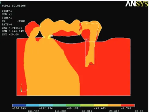
In the supporting bone around the implant abutment, the maximum compressive stress concentrations were
seen in the crestal zones (Figure 1). In the supporting bone around the implant abutment, the compressive stress concentrations were moderate toward the apical third zone. In the supporting bone around the second premolar abutment, the maximum compressive stress concentrations were seen in the cervical zone and distal alveolar crest zone (Figure 1). In the supporting bone around the implant abutment, the maximum
compres-sive stress concentration of −83.33 MPa was seen in the
cervical zone. In the supporting bone around the second premolar abutment, maximum compressive stress
con-centration of −56.509 MPa was seen in the cervical zone
(Figure 1).
Analysis of the Model 2
The stress concentrations were reduced in the support-ing bone around the implant and the natural tooth abut-ments (Figure 2). In the supporting bone around the implant abutment, the maximum compressive stress
concentration of −51.946 MPa was seen in the crestal
zones (Figure 2). In the supporting bone around the implant abutment, the compressive stress concentra-tions were minimal toward the apical third zone. In the supporting bone around the second premolar abutment
compressive stress concentration of −18.269 MPa was
seen (Figure 2).
Analysis of the Model 3
The stress concentrations were very minimal in the porting bone around the implant (Figure 3). In the sup-porting bone around the implant abutment, the
maxi-mum compressive stress concentration of −1.768 Mpa
was seen in the crestal zones (Figure 3). In the support-ing bone around the implant abutment, the compressive stress concentrations were negligible toward the apical third zone. In the supporting bone around the second premolar abutment compressive stress concentration of
−45.463 MPa was seen (Figure 3).
DISCUSSION
The finite element module is a numerical tool which has tremendous power to analyze very complex and irreg-ular bodies.[10] Although it is not a substitute for clinical
experimentation, the use of this method of analysis is justified as it stimulates experimental results, reduces experimentation costs and avoids destructive exper-imentation.[10-12] From an engineering point of view,
tooth-implant supported three-unit fixed partial den-ture may be considered as a multi-component strucden-ture consisting of a complex geometry.[13] Whenever such a
of loads acting on the implant. This should be consid-ered during the planning of implant-natural tooth sup-ported fixed partial dentures.[14,15] The design of
connec-tors in such fixed partial dentures is one of the facconnec-tors which influence the magnitude and the distribution pattern of compressive stress in supporting bone.[9,16,17]
In view of this, it is necessary to biomechanically assess and validate the fixed partial denture connector design which will be most beneficial to its performance with respect to the bone under the loading conditions.[18-20]
Finite element analysis is preferable, as it accurately simulates the real-life situation which can be studied in short time duration.[4,5,21] Therefore, this in vitro method
was selected for the present study, where stress analysis has been carried out to evaluate the effect of connector design in implant-tooth supported fixed partial denture, on magnitude and distribution pattern of compressive stress generated in the supporting bone around the implant and natural tooth abutments in distal exten-sion situation, under static load. A computer simulation operates with several simplifications related to material properties, geometry, load, and interface conditions. For this reason, when applying the results to clinical prac-tice, a qualitative comparison between models is desir-able, rather than focusing on quantitative data from the finite element analysis.[5,21] The ramus and the condyles
of the mandible were not modeled to save the computer memory, processing time and so that the node density could be concentrated on the required area of the man-dible. The advantages of combining natural tooth and implant abutment are the elimination of placement of additional implants, minimum surgical trauma, over-riding the anatomical barriers and providing cost-effec-tive prosthodontic treatment.[22]
It was seen that the maximum compressive stress con-centrations were in the crestal zones and cervical zones of the supporting bone around the implant abutment in all the models (Figures 1-3). The implant movements in alveolus are at the micron level due to the rigid con-tact between bone and implant,while masticatory forces compress the natural tooth into alveolus, which causes
strain within the implant and supporting bone.[5,9,23]
Compared with natural teeth, implant’s rotation center is much cervical at the crestal bone level. Therefore, stress accumulation occurred in the crestal bone area, due to the movement of the implant around this rotation center. As we go apically, the compressive stress concentrations were reduced, and very minimal to negligible stress con-centrations were found in the apex of the implant.[23]
Comparatively greater compressive stress concen-trations were generated in the model with the rigid
connectors (Figure 1) than the models with nonrigid connector (Figures 2 and 3). It was noticed that pro-viding optimum vertical movement in the connector allowed stress dissipation to occur, relieving the sup-porting bone around the implant from the undue com-pressive stress, and allowed wider stress distribution.
Figure 1: Compressive stress concentrations in model 1
Figure 2: Compressive stress concentrations in model 2
FEM analysis of compressive stress in implant-tooth FPD IJPCDR
These recommendations are consistent with the study, in which a decline in the compressive stress con-centrations was seen in the supporting bone around the implant abutment in model 2 and model 3 with nonrigid connectors (Graph 1).
Limitations of This Study
The simulation of the supporting tissues as homoge-nous, isotropic, and linearly elastic structures is an obvi-ous simplification.
Assumption of the complete continuous direct con-tact of the bone to the implants which may not be feasi-ble clinically.
Hence, long-term in vivo study to support the above tests may be carried out.
CONCLUSION
In the supporting bone around the implant abutment, the maximum compressive stress concentrations were seen in the crestal zones of Model 1 with the rigid connector.
The compressive stress concentrations were reduced in the supporting bone around the implant and the natural tooth abutments models with nonrigid connector.
In the supporting bone around the implant abut-ment, the minimum compressive stress concentrations were seen in the crestal zones of models with nonrigid connector.
The compressive stress concentrations were very minimal in the supporting bone around the implant in model 3 with the distal nonrigid connector.
In the supporting bone around the implant abut-ment, the compressive stress concentrations were mini-mal toward the apical third zone in all the models.
The compressive stress concentrations were mini-mal in the cervical zone of supporting bone around the
implant and the natural tooth abutments in the models with the nonrigid connector.
Clinical Significance
It may be recommended that when mesial natural tooth and distal implant are used together as abutments for three-unit fixed partial denture prosthesis in dis-tal extension situation, the nonrigid connector may be placed on the mesial side of the distal implant abutment.
REFERENCES
1. Misch CE. Dental Implant Prosthetics. 1st ed. Michigan: Elsevier Mosby; 2005. p. 1-70.
2. Rangert B, Jemt T, Jorneus J. Forces and moments on Branemark implants. Int J Oral Maxillofac Implants 1989;4:241-7.
3. Skalak R. Osseo integration biomechanics. J Oral Implantol 1986;12:350-6.
4. Misch CM, Ismail YH. Finite element stress analysis of tooth-to-implant fixed partial denture designs. J Prosthodont 1993;2:83-92.
5. Ozcelik TB, Ersoy AE. An investigation of tooth/ implant-supported fixed prosthesis designs with two differ-ent stress analysis methods: An in vitro study. J prosthodont 2007;16:107-16.
6. McGlumphy EA, Campagni WV, Peterson LJ. A compari-son of the stress transfer characteristics of a dental implant with a rigid or a resilient internal element. J Prosthet Dent 1989;62:586-93.
7. Rangert B, GunneJ, Sullivan DY. Mechanical aspects of a Branemark implant connected to a natural tooth: An in vitro
study. Int J Oral Maxillofac Implants 1991;6:177-86.
8. Weinberg LA. The biomechanics of force distribution in implant-supported prostheses. Int J Oral Maxillofac Implant 1993;8:19-31.
9. Weinberg LA, Kruger B. Biomechanical considerations when combining tooth-supported and implant-supported prostheses. Oral Surg Oral Med Oral Pathol 1994;78:22-7. 10. Ericsson I, Lekholm U, Branemark PI, Lindhe J, Glantz PO,
Nyman S. A clinical evaluation of fixed bridge restorations supported by the combination of teeth and osseointegrated titanium implants. J Clin Periodontol 1986;13:307-12. 11. El Charkawi HG, Zerkry KA, El Wakad MT. Stress
analy-sis of different osseointegrated implants supporting a distal extension prosthesis. J Prosthet Dent 1994;72:614-22. 12. Van Rossen IP, Braak LH, de Putter D, de Groot K.
stress-ab-sorbing elements in dental implants. J Prosthet Dent 1990;64:198-205.
13. Cho GC, Chee WW. Apparent intrusion of natural teeth under an implant-supported prosthesis: A clinical report. J Prosthet Dent 1992;68:3-5.
14. Lundgren D, Laurell L. Biomechanical aspects of fixed bridgework supported by natural teeth and end osseous implants. Periodontol 2000 1994;4:23-40.
15. Breeding LC, Dixon DL, Sadler JP. Mechanical consider-ations for the implant tooth-supported fixed partial denture. J Prosthet Dent 1995;74:487-92.
16. Uysal H, Iplikeioglu H, Avei M. Efficacy of the intra mobile
Graph 1: Graphical representation of compressive stress
prostheses. J Prosthet Dent 1997;77:39-45.
18. Tuncelli B, Poyrazoglu E, Koyluoglu AM, Tezcan S. Comparison of load transfer by implant abutments of var-ious diameters. Eur J Prosthodont Restor Dent 1997;5:79-83. 19. Schlumberger TL, Bowley JF, Maze GI. Intrusion
phenome-non in combination tooth-implant restorations: A review of the literature. J Prosthet Dent 1998;80:199-203.
20. Naert IE, Ducyk JA, Hosny MM, Van Steenberghe D. Freestanding and tooth-implant connected prostheses in the
21. Menicucci G, Mossolov A, Mozzati M, Lorenzetti M, Preti G. Tooth-implant connection: Some biomechanical aspects based on finite element analyses. Clin Oral Implants Res 2002;13:334-1. 22. Kronstrom M, Trulsson M, Soderfeldt B. Patient evaluation
of treatment with fixed prostheses supported by implants or a combination of teeth and implants. J prosthodont 2004;13:160-5.