DOI: 10.5098/hmt.v2.3.2001 ISSN: 2151-8629
RECENT ADVANCES IN UNDERSTANDING OF MASS TRANSFER
PHENOMENA IN DIRECT METHANOL FUEL CELLS OPERATING
WITH CONCENTRATED FUEL
Q.X. Wu
a, Y.L. He
b, T.S. Zhao
a,b,*a
Department of Mechanical Engineering, The Hong Kong University of Science and Technology, Clear Water Bay, Kowloon, Hong Kong, China b Key Laboratory of Thermo-Fluid Science and Engineering of MOE, State Key Laboratory of Multiphase Flow in Power Engineering, School of
Energy and Power Engineering, Xi’an Jiaotong University, Xi’an, 710049, P.R. China
A
BSTRACTRunning direct methanol fuel cells (DMFC) with concentrated fuel is desirable to maximize the specific energy of the fuel cell system and to improve the performance by mitigating the water flooding problem associated with diluted methanol operation. This article provides a comprehensive review of recent advances in understanding mass transport phenomena in DMFCs operating with concentrated fuel. The review starts with elaborating the key issues of mass transport of reactants and products associated with highly-concentrated methanol operation, followed by summarizing and discussing past experimental and numerical investigations into the effects of the membrane electrode assembly (MEA) design, flow field structure and operating conditions on the mass transport characteristics and the cell performance. Finally, future opportunities and challenges regarding the mass transport of DMFCs operating with concentrated fuel are also highlighted.
Keywords: Fuel cell; Direct methanol fuel cell; Concentrated methanol; Specific energy; Mass transport
* Corresponding author. Email: metzhao@ust.hk
1. INTRODUCTION
A direct methanol fuel cell (DMFC) is an electrochemical energy-conversion device that converts the chemical energy stored in methanol into electricity directly. Owing to its unique advantages such as simplicity, high-specific energy, facile fuel storage and transportation as well as environmental friendliness, the DMFC has been identified as one of the most appealing candidates to replace batteries in portable applications including laptops, cell phones and personal digital assistances (Hogarth et al., 1997; Larmine and Dicks, 2003; Scott et al., 1999; Yang et al., 2005). Conventionally, as the result of methanol crossover, extremely diluted methanol solution (i.e., 2.0 - 4.0 M) is fed to the DMFC to limit the adverse consequence of methanol crossover, namely, the mixed-potential at the cathode and the reduction in fuel-utilization efficiency. Although a decent performance can be achieved with the low-concentration operation, the most striking feature of the DMFC, high-specific energy (~ 4900 Wh L-1), is inevitably sacrificed (Yang et al., 2010). Moreover, as commonly-used Nafion® membranes
are easily permeable to water, the presence of excess water in the anode of the DMFC can lead to an undesirably large permeation rate of water through the membrane to the cathode. As a consequence, the so-called water flooding problem, shortage in pathways for oxygen transport due to the accumulation of liquid water in the cathode, is exacerbated, lowering the cathode performance. Because of such inherent drawbacks associated with the low-concentration operation, operating DMFCs with concentrated fuel becomes more attractive and significant for the improvement in both the specific energy and the cell performance.
The purpose of this review is to summarize recent advances in the development of DMFCs operating with highly-concentrated methanol solution and highlight future research directions. The remainder of the article is organized as follows: Section 2 gives a general description of the DMFC system; Section 3 elaborates the critical transport issues associated with methanol, carbon dioxide, water and oxygen; Section 4 reviews past efforts on the mass transport of methanol at the high-concentration operation; Section 5 focuses on the water transport in the DMFC operating with concentrated fuel; Section 6 deals with the oxygen transport at the cathode; Section 7 discusses the modeling of the DMFC operating with concentrated fuel; finally, a summary is presented in Section 8.
2. GENERAL DESCRIPTION OF THE FUEL CELL
SYSTEM
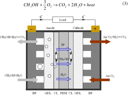
As illustrated in Fig. 1, a typical design of the single DMFC consists of a membrane electrode assembly (MEA) sandwiched by anode and cathode bipolar plates (BP). The BP not only provides flow channels for the delivery of reactants and the removal of products, but also helps collect the generated current in the cell. The MEA, heart of the DMFC, is an integrated multi-layered structure that comprises an anode gas diffusion layer (GDL), an anode catalyst layer (CL), a polymer electrolyte membrane (PEM), a cathode CL, and a cathode GDL. The function of the membrane is to conduct protons from the anode to cathode, and it simultaneously serves as a separator between these two electrodes. Typically, perfluorinated sulfonic acid ion-exchange membranes, developed by DuPont and trademarked as Nafion®, are
Frontiers in Heat and Mass Transfer
DOI: 10.5098/hmt.v2.3.2001 ISSN: 2151-8629 employed in DMFCs. The basic functions of each GDL include
providing mechanical support for the corresponding CL, evenly distributing reactants over the entire CL, and conducting electrons to the flow field, i.e., BP. The GDLs at both the anode and cathode usually consist of two layers, a backing layer that is made of carbon cloth or carbon paper with macro pores (~ 30 µm), and a micro-porous layer (MPL, ~ 0.1 µm) that is composed of hydrophobic polymer and carbon powder. Unlike the GDLs, both the CLs are made of catalysts mixed with ionomer to provide triple-phase boundaries for the methanol oxidation reaction (MOR) and oxygen reduction reaction (ORR). Usually, a diluted methanol solution is directly supplied to the anode as the fuel, while oxygen/air is supplied to the cathode as the oxidant. In the anode CL, with the presence of catalysts, part of methanol reacts with water to generate CO2, protons, electrons and heat, i.e.:
heat e H CO O H OH
CH + → + ++ −+
6 6 2 2
3 (1)
while the remainder of methanol can cross through the membrane to the cathode, where methanol is chemically oxidized to create a so-called mixed potential and thus lowers the cathode potential. In addition to methanol, water in the anode CL may also permeate through the membrane to the cathode, driven by concentration gradient and electro-osmotic drag (EOD) along with protons migration. The so-called “water crossover” not only results in a significant reactant (water) loss from the anode but also aggravates the cathode water flooding. In the cathode CL, part of oxygen reacts with the protons that are conducted through the polymer electrolyte membrane from the anode and the electrons that come from the external circuit to form water and heat as follows:
heat O H O e
H++ −+ → +
2 2 3
2 3 6
6 (2)
while the remaining oxygen in the cathode CL chemically reacts with the permeated methanol from the anode to produce CO2, water and
heat. The two electrochemical reactions 1 and 2 form the following overall cell reaction:
heat O H CO O OH
CH3 + 2→ 2+2 2 +
2
3 (3)
Fig. 1 Schematic of a conventional DMFC.
In terms of the subsystem for supplying/removing reactants/products, DMFC systems can be classified into active and passive systems. The active DMFC system includes a liquid pump to supply/remove the anode reactant (fuel)/product (CO2) to/from the anode flow-field, and a
gas blower/compressor to supply/remove the cathode reactant (oxygen)/product (water) to/from the cathode flow-field. On the other hand, a DMFC that contains no liquid pumps and gas blowers/compressors is referred to as a passive system. Unlike active systems, passive DMFCs utilize passive forces such as diffusion, capillarity, gravity and natural convection to supply and remove
reactants and products, thus generating no parasitic power loss and simplifying the overall fuel cell system.
3. CRITICAL MASS TRANSPORT ISSUES WITH
CONCENTRATED-METHANOL OPERATION
This section describes the transport processes of reactants and products including methanol, carbon dioxide, water and oxygen in a DMFC. Special efforts are made in identifying the critical issues associated with the mass transport of such species in DMFCs operating with highly-concentrated methanol solution.
3.1 Mass transport of methanol and carbon dioxide
Figure 1 illustrates the transport of methanol and carbon dioxide in a conventional DMFC. At the anode, liquid methanol stored in the fuel reservoir is transferred to the anode CL through the anode flow field and the anode GDL by forced convection and diffusion in the active mode or by diffusion in the passive mode. In the anode CL, the methanol is consumed by the anode MOR to produce CO2, as indicated
by Eq. (1). The generated CO2 will be vented out from the anode CL
through the anode GDL and the anode flow field to the ambient at active operation or it may further transport through the fuel reservoir before leaving the cell at passive operation. Clearly, the transport of methanol and CO2 couples intrinsically and depends closely on the
mass-transfer resistance in the anode including the GDL and flow field as well as the operating conditions such as the methanol flow rate, methanol feed concentration and operating temperature. Meanwhile, since the Nafion-type proton-conducting membrane is permeable to methanol, excess methanol in the anode CL can cross through the membrane to the cathode to generate a mixed-potential, decreasing the cell voltage. Thus, the methanol-crossover rate must to be minimized to improve the cell performance. As the transport of methanol through the membrane is driven by molecular diffusion and EOD, lowering the methanol concentration at the anode CL can thus reduce the methanol-crossover rate. On the other hand, too low-methanol concentration at the anode CL will lead to a severe concentration polarization, which also increases the anode overpotential. Therefore, it is critical to maintain an adequate methanol concentration at the anode CL. However, it is rather challenging to achieve this especially in the DMFC operating with concentrated fuel, as the methanol concentration at the anode CL is intrinsically influenced by the transport of water and CO2. A change in one of the three mass transport processes of
methanol, water and CO2 will cause a change in the other two. In
summary, how to manage the transport of methanol, CO2 and water so
as to obtain an adequate methanol concentration at the anode CL at a given current density is one of the most critical issues in the design of a DMFC operating with concentrated fuel.
3.2 Mass transport of water
Unlike the diluted-methanol operation, in which excess water is directly fed to the anode, part of/all the water needed for the anode MOR with the concentrated-methanol operation should be obtained from the produced water at the cathode. Under this circumstance, if a DMFC is not properly designed, the water transport flux from the cathode to anode may be insufficient, thereby leading to a low limiting current density caused by the water transport limitation. In addition, the improper design can also result in a low water concentration at the anode CL, which may pose four problems: 1) the incomplete oxidation of methanol becomes significant such that the formation of undesirable and poisonous products including formic acid, formaldehyde, methyl formate and methylal increases, lowering the Faradic efficiency of the fuel cell; 2) the concentration of OHads on the surface of the PtRu
catalyst is not enough to desorb the adsorbed intermediates such as COads, thereby increasing the anode overpotential; 3) the humidification
DOI: 10.5098/hmt.v2.3.2001 ISSN: 2151-8629 further increases the anode overpotential; and 4) the Nafion membrane
is not well humidified, lowering the proton conductivity of the membrane, creating a high internal resistance. Therefore, the critical issue in DMFCs operating with concentrated fuel is how to transport part of the produced water from the cathode to anode to maintain a sufficiently high mole ratio of water to methanol to simultaneously improve the anode performance and lower the internal resistance.
3.3 Mass transport of oxygen
At the cathode, oxygen is transported to the cathode flow field either by a blower/compressor in the active operation or by natural convection in the passive operation. It will then transport through the cathode flow field and the cathode DL to the cathode CL, where it reacts with the protons and electrons, coming from the anode, to form water. At high current densities, as the demand of oxygen for ORR becomes larger, the concentration loss of oxygen through the cathode may be a limiting factor that hinders the ORR reaction. Since the feed concentration of oxygen is fixed, the oxygen concentration at the cathode CL depends primarily on the mass-transfer resistance in the cathode including the flow field and GDL. Under this circumstance, the critical issue in the design of the DMFC cathode is how to minimize the oxygen transport resistance from the flow field to the cathode CL to facilitate the oxygen transport. However, because oxygen transport is coupled to the counter-current water transport in the cathode, lowering the mass-transfer resistance in the cathode can enhance the water removal from the cathode. The enhancement of water removal is undesirable for the DMFCs operating with neat methanol or highly-concentrated methanol as it will result in an insufficient water transport flux from the cathode to anode for the MOR consumption and a low water concentration at the anode CL. Hence, it is of great importance to recognize that in the DMFC under concentrated-methanol operation, the design of the cathode structure and operating conditions must consider the oxygen transport and water transport simultaneously so that both oxygen concentration loss in the cathode and water concentration loss in the anode can be minimized.
4. METHANOL DELIVERY AND TRANSPORT IN
DMFCS OPERATING WITH CONCENTRATED FUEL
As discussed in the preceding section, it is essential to maintain an adequate methanol concentration in the anode CL at a given current density so that the rate of methanol crossover and mass-transport loss can be minimized and thus cell voltage can be maximized. Since the methanol concentration gradient from the fuel reservoir to the anode CL is excessively steep in the DMFC operating with concentrated methanol solution, the key to the methanol management is how to adjust the methanol mass-transfer resistance to provide an optimal rate of fuel delivery from the fuel reservoir to the anode CL such that the methanol concentration at the anode CL is maintained at an adequate level. In previous investigations (Kim et al., 2006; Pan, 2006; Kim, 2006; Nakagawa et al., 2006; Abdelkareem and Nakagawa, 2006; Zhang and Hsing, 2007; Abdelkareem et al., 2007; Eccarius et al., 2008; Abdelkareem et al., 2010; Tsujiguchi et al., 2010; Chung et al., 2010; Wu et al., 2010; Xu et al., 2010; Li et al., 2010; Feng et al., 2011; Xu et al., 2011;), the proposed ways in regulating the anode mass-transfer resistance to achieve an appropriate methanol concentration level at the anode CL can be divided into two categories: modifications of the anode flow field design and developments of new fuel delivery schemes.
4.1 Modifications of the anode flow field design
As a key component in the DMFC, the anode flow field not only serves to conduct the electrons from the anode GDL, but also provides transport path for methanol, water and CO2. Hence, the anode flow field
plays an important role in the methanol transport. Due to the low mass-transfer resistance of conventional anode flow fields, direct feeding
concentrated methanol solution to the DMFC with a conventional design of the anode flow field can result in a tremendously high methanol-crossover rate, creating the mixed-potential at the cathode. Thus, developing a new anode flow field with a large mass-transfer resistance is of great importance for the DMFC with concentrated fuel operation.
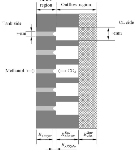
Fig. 2 Illustration of the structure and the mechanism of the
microfluidic-structured flow field (Wu et al., 2010).
Wu et al. (2010) proposed a microfluidic-structured flow field, with which the methanol delivery rate can be reduced so that the methanol concentration at the anode CL can be limited to a sufficiently low level. As shown in Fig. 2, unlike the design of conventional perforated flow fields that consist of plurality of identical circular holes, the microfluidic-structured flow field consists of plurality of coaxial sudden-expansion flow pores, with the smaller pore (on the order of micrometer) in the inflow region interfaced with the fuel reservoir while the bigger pore (on the order of millimeter) in the outflow region interfaced with the anode GDL. Taking advantage of the liquid methanol and gas CO2 two-phase counter flow, the unique fluidic
structure enables the formation of a liquid-gas meniscus in each flow passage. The evaporation from the small meniscus in each flow passage can lead to an extremely large interfacial mass-transfer resistance, creating a bottleneck of methanol delivery to the anode CL. Meanwhile, it is significant to note that the large flow resistance through the microfluidic-structured flow field as a result of the small pore size and open ratio will also lead to a relatively high CO2 concentration at the
anode CL. Thus, CO2 can serve to dilute methanol vapor such that
DOI: 10.5098/hmt.v2.3.2001 ISSN: 2151-8629
Fig. 3 Comparison in cell voltages at constant-current (50 mA cm-2)
discharging between the passive DMFCs with different anode flow fields (Wu et al., 2010).
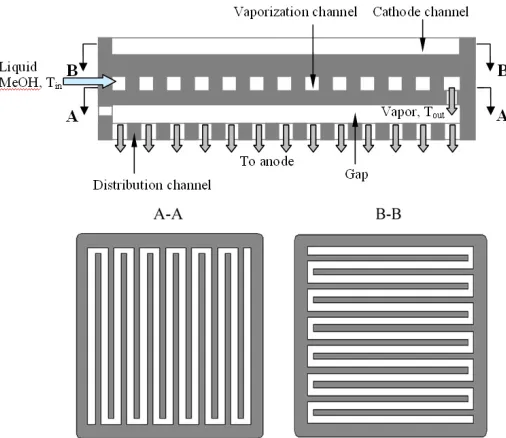
Fig. 4 Schematic of the methanol-vaporization flow field (Xu et al.,
2011).
To simultaneously utilize the dilution effect of CO2 and the heat
generated by the DMFC, Xu et al. (2011) proposed another design of flow field that allowed a single DMFC or a DMFC stack to operate with highly-concentrated methanol. As schematically illustrated in Fig. 4, the flow field basically consists of two parallel flow-channel plates, separated with a gap. The upper plate, grooved to form a serpentine flow channel, is to vaporize a highly-concentrated methanol solution to ensure the fuel to be completely vaporized before it enters the gap, while the lower plate, perforated to form a serpentine flow channel and located between the gap and the MEA, is to uniformly distribute the fuel onto the anode surface of the MEA. The current is collected from the distribution channel. Figure 5 presents the cell polarization curves and power densities of the DMFC with the novel flow field at concentrated methanol operating conditions. It is clear to see from Fig. 5 that the 16.0-M operation exhibits the highest peak power density, 51.6 mW cm-2. Such performance is comparable to that of the DMFC with conventional anode flow field at 2.0-M operation, but the specific energy with the 16.0-M operation is much higher than that with the 2.0-M operation. This fact suggests that the methanol-vaporization flow
field could greatly reduce the rate of methanol crossover so that concentrated methanol solution can be directly used.
0 30 60 90 120 150 180 210 240 270 0.0
0.1 0.2 0.3 0.4 0.5 0.6 0.7
0 10 20 30 40 50 60
MeOH flow rate: 20 µl min-1
P
o
w
e
r
D
e
n
s
it
y
(
m
W
c
m
-2 )
V
o
lt
a
g
e
(
V
)
Current Density (mA cm-2)
Neat MeOH 20.0 M 16.0 M 14.0 M
Temperature: 60 oC
O2: 20 sccm
Fig. 5 Performance of the DMFC with the methanol-vaporization flow
field fed with concentrated methanol (Xu et al., 2011).
4.2 The fuel delivery design
In addition to the anode flow field, the mass-transfer resistance of methanol can also be changed by using different fuel delivery schemes. A simple way to increase the mass-transfer resistance can be achieved by adding an additional transport layer with a large thickness, low porosity and small pore size. For instance, Nakagawa and his co-workers (Nakagawa et al., 2006; Abdelkareem and Nakagawa, 2006; Abdelkareem et al., 2007; Abdelkareem et al., 2010; Tsujiguchi et al., 2010;) employed a hydrophobic porous carbon plate onto the anode flow field to reduce the methanol crossover. Figure 6 shows the transient power density of a passive DMFC with the addition of a porous carbon plate (referred to as PCP-γ3), the thickness, bubble point, Darcy constant of which are 0.5 mm, 3.2 kPa and 2.7×10⁻¹³ m2, respectively. It is interesting to note that this DMFC system can operate with almost pure methanol (90 wt. %) to give fairly high performance, nearly 40 mW cm-2. The stable discharge behavior indicates that the
rate of methanol delivery to the anode electrode can be stably regulated by the system. With this method, Tsujiguchi et al. (2010) recently designed, fabricated and tested an 8-cell passive DMFC stack and showed that this stack could yield a maximum power output of 1.8 W when neat methanol was fed.
Another way to change the mass-transfer resistance in the conventional DMFC design can be obtained by evaporating the liquid methanol into the vapor phase and control the evaporation rate. A simple way to evaporate the liquid methanol can be achieved by placing the DMFC horizontally with the fuel reservoir at the bottom and kept the liquid-gas interface at a certain distance away from the anode flow field. With such a methanol delivery scheme, Chung et al. (2010) showed that the passive DMFC can achieve a peak power density of 15 mW cm-2 when neat methanol was stored in the fuel reservoir. Nevertheless, as this structure is orientation-dependent, neat methanol may drop onto the surface of the MEA under practical operation, generating destructive damage to the MEA.
DOI: 10.5098/hmt.v2.3.2001 ISSN: 2151-8629 density of 34 mW cm-2 and a high fuel efficiency of 62 %, which
indicated that the system could well control the transport rate of methanol from the neat methanol reservoir to the anode CL. Another example is the work by Feng et al. (2011). In their designs, in addition to the use of a phase separation membrane as the pervaporation film, a polycarbonate sheet was attached to the pervaporation membrane so that the methanol delivery rate could be finely controlled.
In summary, increasing the mass-transfer resistance of methanol from the fuel reservoir to the anode CL enables a DMFC to be operated with concentrated fuel and to maintain an adequate methanol concentration level at the anode CL so that the specific energy of the system can be maximized.
Fig. 6 Performance of the DMFC with a porous carbon plate
(Abdelkareem et al., 2010).
5. WATER TRANSPORT IN DMFCS OPERATING
WITH CONCENTRATED FUEL
At the high-concentration operation, as little water or no water is fed to the anode, water in the anode CL may become insufficient for the anode MOR. Hence, part of the produced water at the cathode needs to be transported to the anode to compensate the anode MOR. To transport the produced water from the cathode to anode, two methods can be used: i) transporting the water through the membrane by diffusion; and ii) collecting the water at the cathode flow field exit and pumping it to the anode. Since the first method consumes no additional power and simplifies the system design, this review mainly focuses on the water transport issues associated with the first method.
The water transport through the membrane is by three mechanisms: EOD by protons migration, diffusion by concentration gradient and convection by hydraulic pressure gradient. The water flux due to EOD,
JE, can be determined from:
F i n
JE = d,W (4)
where nd,W stands for the EOD coefficient of water; i is the cell current
density; F denotes the Faraday’s constant. Clearly, the EOD flux depends on the cell current density and nd,W, which is related to the
water content in the membrane.
In addition, as little or no water is supplied to the anode and it is consumed in the anode CL but produced at the cathode, the water concentration at the cathode CL may be higher than that at the anode, creating a water concentration gradient across the membrane. Such a concentration gradient can drive water to diffuse from the cathode to anode; the diffusion flux, JD, can be expressed by Fick’s law:
Mem ACL CCL D
C C D J
δ
− = eff
N W,
(5)
where CCCL and CACL represent the water concentration at the cathode
CL and anode CL, respectively; eff N W,
D is the effective diffusion coefficients of dissolved water;
Mem
δ
denotes the thickness of the polymer electrolyte membrane. Equation (5) indicates that the diffusion flux depends on the water concentration level at each side of the membrane and the membrane properties including thickness, water uptake characteristics, and effective diffusivity of dissolved water. Generally, CCCL is influenced by the water production flux at thecathode that is related to cell current density and the methanol-crossover flux, the structure of the cathode GDL including the PTFE loading in the GDL and its thickness, the cathode flow field design, the operating temperature and the relative humidity of the cathode gas. The water concentration at the anode CL, CACL, can be affected by the water
consumption flux at the anode that is related to the cell current density and the design of the anode GDL such as its thickness and porosity. In summary, the magnitudes of CCCL, CACL and the JD are all depends on
the designs of the MEA and the flow fields as well as the operating conditions.
Fig. 7 Schematic of the DMFC with pervaporation membrane (Xu et
al., 2010).
Another important contribution to water transport through the membrane is the water flux due to convection, which depends on the liquid pressure difference across the membrane and can be expressed as:
Mem O H
c a m C
M p p K J
δ µ
ρ
2
)
( −
= (6)
where Km is the permeability through the membrane, ρ is density of
water, µ is viscosity of liquid water, MH2O is molecular weight of water,
and pa as well as pc represent, respectively, liquid water pressure at the
anode and cathode. Equation (6) indicates the convection water flux depends on the membrane properties, and the liquid pressure of the anode and cathode, which are related to the MEA structure design.
In summary, the total water transport flux through the membrane, J, can be obtained by summing up Eqs. (4)-(6) to give:
Mem O H
c a m
Mem ACL CCL eff d C D E
M p p K C C D F
i n J J J J
δ µ
ρ
δ 2
)
( −
+ − +
− = + + −
= (7)
Equation (7) indicates that the net water transport flux through the
membrane is influenced by all the parameters that affect JD, JE and JC
DOI: 10.5098/hmt.v2.3.2001 ISSN: 2151-8629
et al., 2010; Park et al., 2010; Li et al., 2010; Wu et al., 2010; Masdar
et al., 2010; Li et al., 2010; Xu et al., 2011; Wu et al., 2011; Wu and Zhao, 2011; Li et al., 2011;).
0 1 2 3
0.00 0.05 0.10 0.15 0.20 0.25 0.30 0.35
Without a SiO2 layer 0.1 mg cm-2 SiO2 at the anode 0.1 mg cm-2
SiO2 at the cathode
0.1 mg cm-2 SiO2 at both the anode and cathode
C
e
ll
v
o
lt
a
g
e
(
V
)
Time (h)
(a)
0 1 2 3
0.35 0.40 0.45 0.50 0.55 0.60 0.65 0.70
Without a SiO2 layer 0.1 mg cm-2 SiO2 at the anode 0.1 mg cm-2
SiO2 at the cathode
0.1 mg cm-2 SiO2 at both the anode and cathode
A
n
o
d
e
o
v
e
rp
o
te
n
ti
a
l
(V
)
Time (h)
(b)
0 1 2 3
0.40 0.45 0.50 0.55 0.60 0.65 0.70
Without a SiO2 layer 0.1 mg cm-2 SiO2 at the anode 0.1 mg cm-2
SiO2 at the cathode
0.1 mg cm-2 SiO2 at both the anode and cathode
C
a
th
o
d
e
o
ve
rp
o
te
n
ti
a
l
(V
)
Time (h)
(c)
Fig. 8 Transient performances at 90 mA cm-2 of passive DMFCs with
and without SO2 layers: a) cell voltage; b) anode overpotential;
c) cathode overpotential (Wu et al., 2010).
5.1 Effect of the anode GDL
In the highly concentrated-methanol or neat-methanol operation, as little water is present in the fuel reservoir, the water in the anode CL can transport from the anode CL through the anode GDL to the fuel reservoir. Hence, the design of the anode GDL can influence the water
concentration at the anode CL and thus the diffusion flux through the membrane. To understand the effect of the anode GDL, Wu and Zhao (2011) developed an in-situ method to measure the water transport flux from the cathode to anode. It is found that an increase in the anode GDL thickness leads to a decrease in the water transport flux from the cathode to anode. This can be attributed to a decrease in the water diffusion flux through the membrane due to an increase in the mass-transfer resistance of water through the anode. Interestingly, it is also found that although the water transport flux through the membrane is decreased, the cell performance improves with a thicker anode GDL. This is due to the fact that a thicker anode GDL results in a larger mass-transfer resistance, which helps reduce the water loss from the anode CL to the fuel reservoir and thereby increasing the water concentration at the anode CL. However, it should be pointed out that a too thick GDL can lead to a decrease in the limiting current density caused by the methanol transport limitation. Therefore, to avoid severe transport loss of methanol, the mass-transfer resistance of the anode GDL should not be too large.
5.2 Effect of the membrane
As indicated in Eqs. (5) and (6), the physical properties of the membrane such as the thickness, effective diffusivity and permeability can influence both the diffusion flux and the convection flux. Thus, the membrane is a key factor that affects the water transport through the membrane. Li et al. (2010) found that at the 16.0 M operation, the water transport flux from the cathode to anode increased with a decrease in the membrane thickness because a thinner membrane resulted in a lower mass-transfer resistance of the membrane so that the diffusion and convection of water through the membrane from the cathode to anode is enhanced. Moreover, they showed that the use of thinner membranes can also lead to an increase in the water concentration at the anode CL, thereby resulting in a lower internal resistance and a better cell performance. Recently, Wu and Zhao (2011) found that similar to the behavior observed in the 16.0 M operation, the transport of water through the membrane in the neat-methanol operation was also facilitated by employing a thin membrane such as Nafion 112. More importantly, their results showed that a thin membrane not only can lower the internal resistance but can also improve the anode MOR performance as the result of increased water concentration at the anode CL. These facts suggest that lowering the mass-transfer resistance of the membrane is an effective way to increase both the water transport through the membrane and the water concentration at the anode CL so that a lower internal resistance and a higher anode performance can be achieved.
Although thin membranes are helpful for the improvement in the water management, only using thin membranes in the neat-methanol operation is far from enough. To further increase the performance of the DMFC with thin membrane, Wu et al. (2010) proposed to add a water retention layer, composed of nanosized SiO2 and Nafion ionomer, onto
each side of the Nafion 212 membrane. Taking advantage of the hygroscopic nature of SiO2, the cathode water retention layer can help
maintain the water produced from the cathode at a higher concentration level to enhance the water transport to the anode, while the anode retention layer can retain the water that is transported from the cathode. As a result, a higher water transport rate and a higher water concentration at the anode CL can be achieved. The transient performances at 90 mA cm-2 of a passive DMFC with and without SO2
layers are shown in Fig. 8. It is observed from Fig. 8a that the cell voltage of the DMFC with the water retention layers on both the anode and cathode is the highest among all the cases; it is about 12 mV higher than that with a single water retention layer and 43 mV higher than that without any water retention layers. To understand the effect of SO2
DOI: 10.5098/hmt.v2.3.2001 ISSN: 2151-8629 DMFC with the two water retention layers can be mainly attributed to
the reduction in the anode overpotential as a result of the elevated water concentration at the anode CL. This point is further confirmed by Fig. 8c, which shows that the cathode overpotential with the two water retention layers is only 13 mV higher than that without any water retention layers.
5.3 Effect of the cathode GDL
As the water production flux in the cathode CL is fixed for given operating conditions and structure designs of the anode and membrane, the water removal from the cathode is intrinsically coupled to the water transport through the membrane. Thus, extensive efforts (Guo and Faghri, 2006; Xu et al., 2010; Masdar et al., 2010; Li et al., 2010; Wu and Zhao, 2011; Wu et al., 2011; Li and Faghri, 2011; Xu et al., 2011) have been made to the study of the effects of cathode GDL design parameters on the water transport through the membrane in DMFCs operating with concentrated fuel. Wu an Zhao (2011) found that at the neat-methanol operation, the water transport flux through the membrane was rather sensitive to the change in the mass-transfer resistance of the cathode GDL: an increase in the cathode GDL thickness can greatly increase the water transport flux through the membrane due to the decreased water removal flux. Later, Wu et al. (2011) further investigated the effects of the design parameters of the cathode GDL, including the PTFE content in the BL, and the carbon loading and the PTFE content in the MPL on the performance of a passive DMFC operating with neat methanol. Their results indicates that on one hand, these parameters can be adjusted to decrease the water concentration loss of the anode performance, but on the other hand, they can also cause an increase in the oxygen concentration loss of the cathode performance. Hence, an optimal balance in minimizing the both concentration losses is the key to maximize the cell performance. Rather than adjusting the parameters of the commonly-used cathode GDL, Xu et al. (2010) added a water management layer (WML) between the cathode GDL and the cathode flow field, and tested this new MEA in a passive DMFC operating with neat methanol. The WML used in their work, consisted of two carbon clothes with a thicknesses of 350 µm and 50 wt. % PTFE treatment. They found that the addition of the WML can increase the mass-transfer resistance of the cathode GDL so that less water was lost to the ambient and more water was transported through the membrane to the anode. As a result, the cell performance got improved. Meanwhile, they also concluded that the addition of the WML can reduce the methanol crossover due to the dilution effect of the water in the anode CL. However, it is important to note that the dilution effect of water is significant only if liquid water exists in the anode CL.
Limited by the internal resistance, the addition of more layers between the cathode GDL and the flow field to increase the mass-transfer resistance of cathode is impractical. Hence, researchers tried to create a large mass-transfer resistance outside the cathode flow field. Masdar et al. (2010) found that the water management in the DMFC operating with concentrated fuel was improved by fixing a hydrophobic air filter (HAF) to the cathode. By using in situ mass spectrometry, they confirmed that the partial pressure of water vapor in the anode increased with the application of an HAF, thus resulting in a lower membrane resistance and a higher performance. In a similar manner, Li
et al. (2011) proposed adopting a perforated cover onto the cathode flow field surface and demonstrated that the water transport through the membrane enhanced significantly with the presence of the perforated cover. By optimizing the open ratio of the perforated cover, a peak power density of 22.7 mW cm-2 and a fuel efficiency of 70.1 % were
achieved in their DMFC.
5.4 Effect of the operating conditions
The main operating conditions that affect the water transport through the membrane include the current density, operating temperature, oxygen flow rate, methanol concentration and cathode gas relative
humidity (Abdelkareem et al., 2007;Eccarius et al., 2008; Li et al., 2010; Li et al., 2010; Wu and Zhao, 2011).
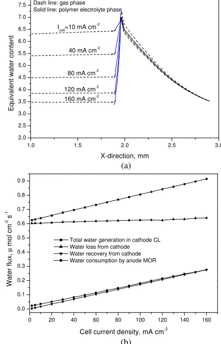
Figure 9 shows the effect of current density on the water transport flux from the cathode to anode with the neat-methanol operation. It is seen that the water transport flux through the membrane increases with current density. Such a behavior can be attributed to the fact that the water concentration at the anode CL decreases, whereas it increases at the cathode CL with current density. More importantly, it is observed from Fig. 9 that the EOD flux is significantly high, suggesting that a large portion of water driven by diffusion from the cathode to anode can be moved back to the cathode by EOD, resulting in a smaller net water flux to the anode. Hence, the MEA should be designed to create a sufficiently large water concentration gradient across the membrane to offset such a high EOD flux to ensure a sufficiently great water flux for the anode MOR.
0 30 60 90 120
0.0 0.3 0.6 0.9 1.2 1.5 1.8 2.1 2.4 2.7
W
a
te
r
fl
u
x
(
µ
m
o
l
s
-1 c
m
-2 )
Current density (mA cm-2) Nafion 112, 30 oC
Diffusion flux EOD flux
Water transport flux to the anode
Fig. 9 Variations in the diffusion flux, EOD flux, and water transport
flux from the cathode to the anode with current density (Wu and Zhao, 2011).
0 30 60 90 120 150 180 210
0.0 0.1 0.2 0.3 0.4 0.5 0.6 0.7 0.8 0.9 1.0
W
a
te
r
tr
a
n
s
p
o
rt
f
lu
x
f
ro
m
t
h
e
c
a
th
o
d
e
to
t
h
e
a
n
o
d
e
(
µ
m
o
l
c
m
-2 s -1 )
Current density (mA cm-2)
Nafion 112
30 oC
45 oC
60 oC
Fig. 10 Effect of cell temperature on the water transport flux from the
cathode to the anode (Wu and Zhao, 2011).
DOI: 10.5098/hmt.v2.3.2001 ISSN: 2151-8629 temperature: when the cell temperature rises from 30 to 60 oC, the water
flux increases from 0.269 to 0.604 µmol cm-2 s-1 at the current density
of 60 mA cm-2. Such an increase in the water transport flux through the membrane can be attributed to a higher water production flux caused by the permeated methanol at the cathode and a bigger effective diffusion coefficient of water through the membrane at elevated temperatures.
To prevent cathode flooding in DMFCs operating with diluted methanol solution, a sufficiently high oxygen flow rate is usually required to sweep out liquid water from the cathode GDL and flow channel. At the concentrated-methanol operation, however, it was found that a high flow rate of oxygen may simultaneously cause a decrease in the water transport flux from the cathode to anode (Abdelkareem et al., 2007; Eccarius et al., 2008; Li et al., 2010). An increase in the oxygen flow rate reduces the water concentration in the cathode CL as a result of the enhanced water removal rate from the cathode. Thus, the water diffusion flux from cathode to anode and the water concentration at the anode CL is reduced, resulting in an increased internal resistance and a decreased anode MOR performance.
The influence of methanol concentration on water transport flux through the membrane has also been studied (Li et al., 2010). It was found that the water transport flux from the cathode to anode increased with methanol concentration. On one hand, an increase in the methanol concentration leads to a lower water concentration in the anode CL so that the diffusion flux from the cathode to anode is increased, while the EOD flux in an opposite direction is decreased because the EOD coefficient of water decreases with water content of the membrane. On other hand, the increased methanol concentration also causes a higher methanol-crossover flux, thus resulting in a larger water production flux at the cathode. Therefore, the water transport flux through the membrane increases with methanol concentration.
Another operating condition that influences the water transport is the cathode relative humidity. Li et al. (2010) found that an increase in the cathode relative humidity leads to a higher water transport flux from the cathode to anode. This can be simply attributed to the increased water diffusion flux due to a larger water concentration gradient across the membrane with a higher relative humidity.
The above discussion indicates that the water transport in DMFCs operating with concentrated fuel is influenced by the MEA design and the operating conditions. The key to lower the internal resistance and improve the anode performance is to enhance water transport from the cathode to anode to maintain a sufficiently high water concentration level by properly designing the MEA and optimizing the operating conditions
6. OXYGEN TRANSPORT IN DMFCS OPERATING
WITH CONCENTRATED FUEL
The oxygen management in DMFC systems operating with highly concentrated fuel is somewhat different from that in conventional DMFC systems operating with diluted methanol solution. As water crossover from the anode to cathode is substantial and tends to exaggerate the cathode flooding problem, a high cathode gas flow rate and a large open ratio of the cathode flow field are usually needed to enhance the oxygen transport in the active mode and the passive mode, respectively. With the concentrated-methanol operation, however, the so-called water crossover is from the cathode to anode, and thus the water flooding problems is greatly mitigated. Hence, the oxygen transport becomes easier in the DMFC operating with concentrated fuel. In addition, as discussed in Section 5, increasing the gas flow rate or reducing the cathode mass-transfer resistance will decrease not only the water transport flux through the membrane but also the water concentration at the anode CL, which results in a higher internal resistance and a poorer anode performance (Abdelkareem et al., 2007; Eccarius et al., 2008; Li et al., 2010; Wu and Zhao, 2011; Wu et al., 2011). Therefore, in DMFC systems operating with concentrated fuel, a low cathode gas flow rate or an air-breathing mode and a large cathode mass-transfer resistance are preferable.
(a)
(b)
Fig. 11 Schematic of (a) the passive DMFC operating with neat
methanol and the coordinate system, and (b) the methanol transport barrier (Yang et al., 2011).
7. MODELING OF DMFCS OPERATING WITH
CONCENTRATED FUEL
As the intrinsically coupled physicochemical processes occur simultaneously in DMFCs, including heat and mass transfer, electrochemical reactions, as well as ionic and electronic transfer, it is difficult to quantify experimentally the interrelated parameters that govern the fuel cell. Therefore, numerical modeling that incorporates coupled heat and mass transport as well as electrochemical kinetics becomes essential to gain a better understanding of DMFCs and to shorten the design and optimization cycles.
During the past decades, extensive efforts have been devoted to the development of mathematical models for DMFCs operating with diluted methanol (Wang and Wang, 2003; Divisek et al., 2003; Murgia
DOI: 10.5098/hmt.v2.3.2001 ISSN: 2151-8629 DMFC operating with neat methanol. Their results revealed the
transient behaviors of voltage output, methanol fraction, temperature, overpotentials and methanol crossover through the membrane in the DMFC at the neat-methanol operation. More recently, Xu and Faghri (2010) developed a two-dimensional, two-phase, non-isothermal model based on the multi-fluid approach for the DMFC fed with concentrated fuel. In their model, the vapor generation through a pervaporation membrane, the vapor transport through a hydrophobic vapor transport layer and the non-equilibrium evaporation/condensation of methanol and water in the GDLs and CLs were considered. With this model, the effects of various operating parameters and cell structure designs on the mass transport and cell performance were numerically investigated. Also, it was shown that the mass transport and cell performance depended highly on both the open ratio of the pervaporation membrane and the methanol concentration in the fuel reservoir.
An important assumption in the above-mentioned examples of mass transport models for the DMFC operating with concentrated fuel is that substantial amount of liquid water are present in the anode and cathode CLs and GDLs, thus resulting in two-phase flow patterns in both the anode and cathode. Such an assumption is valid when the water vapor partial pressures in the anode and cathode reach the saturated values, which is likely to happen in these cases: i) the fuel contains a large portion of water; ii) extremely low cathode gas flow rates are applied; and iii) both the anode and cathode mass-transfer resistance are significantly large. In a DMFC fed with neat methanol under practical operating operations, however, this assumption may be unrealistic. In addition, the above models do not consider the effect of water concentration on the anode overpotential, which is particularly important at the neat-methanol operation (Wu et al., 2010; Wu et al., 2011). Most recently, to take account for this effect, Yang et al. (2011) developed a one-dimensional, single-phase model for the passive DMFC at the neat-methanol operation and the computation domain is illustrated in Fig. 11. The diffusion of dissolved methanol and water through the pervaporation membrane can be modeled by:
P M P D C C J , B interface M, A interface M, diffusion M, / ) ( δ −
= (8)
P W P D C J , B interface W, diffusion W, / ) 0 ( δ −
= (9)
where
P M
D , andDW,Pare the effective diffusion coefficients of
dissolved methanol and water through the pervaporation membrane;
P
δ
is the thickness of pervaporation membrane;A interface M, C , B interface M, C and B interface W,
C represent, respectively, the concentrations of the dissolved methanol at the both sides of the membrane and the dissolved water concentration at Interface B. The fluxes of methanol vaporization and water vapor adsorbed at Interface 1 can be determined by:
) ( MV,interface1
* B interface MV, M desorption M, C RT p h
J = ϕ − (10)
) ( W,N,interfaceB
* 1 interface N, W, W adsorption
W, h C C
J = ϕ − (11)
where
M
h and
W
h are the interfacial transfer rate constants of methanol and water; ϕ is the open ratio of the perforated plate; *
B interface MV, p and * 1 interface N, W,
C denote the saturated pressure of methanol vapor that is in thermodynamically equilibrium with the dissolved methanol at Interface B and equivalent concentration of dissolved water in the pervaporation membrane that equilibrated with water vapor at Interface 1; 1 interface MV, C and B interface N, W,
C are the methanol vapor concentration at Interface 1 and dissolved water concentration at Interface B, respectively.
Table 1 Constitutive correlations and definitions.
Parameters Expressions
Effective diffusion coefficient of species in gas phase = 5 . 1 g i, cc g i, g i, eff g i, ε ε D D D D medium porous collector current chamber vapor 2 2 3OH,H O,O
CH ~ i Effective diffusion coefficient of dissolved species in polymer electrolyte = 1.5 N N i, N i, eff g i,
ε
D D D layer catalyst membrane O H OH, CH ~i 3 2
Mole generation rate of methanol to gas phase − = − 0 Ν g Μ, g MV, R R region other CL anode Mole generation rate of dissolved methanol in polymer electrolyte − = − 0 6 a Ν g Μ, N M, F j R R region other CL anode Mole generation rate of water
to gas phase
= − 0 g N W, g WV, R R region other CL Mole generation rate of dissolved water in polymer electrolyte − − − = − − g N W, a g N W, ccl para c N W, 6 0 6 2 R F j R F i F j R
δ
CL anode membrane CL cathode Mole generation rate of oxygen to gas phase − = 0 4 c g ,O2 F
j R region other CL cathode Correction factor in Eq. (22)
[
coth( ) 1]
) ( 3 agg agg 2 agg −= R R
R
E
φ
φ
φ
where agg c c ref O eff agg , O ref O 0, agg agg 2 exp 2 2 2 R RT F C nFD j A R =α
η
φ
; − + = agg N, s agg N, s agg 1ε
ε
ε
ε
A A ; 5 . 1 agg N, N , O eff agg ,O2 D 2 ε
D =
In the anode and cathode porous regions, the mass transport of methanol vapor, water vapor and oxygen can be modeled by:
0 g MV, g MV, 2 eff g
MV,∇C +R =
D (12) 0 g WV, g WV, 2 eff g
WV,∇ C +R =
D (13) 0 g , O g , O 2 eff g ,
O2 ∇ C 2 +R 2 =
D
DOI: 10.5098/hmt.v2.3.2001 ISSN: 2151-8629 where g MV, C , g , WV
C and
g , O2
C are, respectively, the concentrations of methanol vapor, water vapor and oxygen; eff
g MV,
D , eff g V, W
D and eff g , O2
D denote the effective diffusion coefficients of methanol vapor, water vapor and oxygen;
g MV,
R ,
g V, W
R and
g , O2
R represent the source terms of methanol vapor, water vapor and oxygen (see Table 1).
The interfacial transfer rate between methanol vapor and the dissolved methanol in the ionomers and the one between dissolved water in the ionomers and water vapor can be written as:
) ( * g MV, g MV, M cl s, Ν g
Μ, A h C C
R → = − (15) )
( W,N *W,N W
cl s, g N
W, A h C C
R → = − (16)
where
cl s,
A is the specific surface area between the gas phase and ionomer phase in the anode CL; *
g MV,
C and * N W,
C are the equilibrium concentrations of methanol vapor and dissolved water in the ionomers.
The conservation of dissolved methanol and water through the polymer electrolyte phase can be written as:
0 )
( d,M M,N N
M, 2 eff
N
M, ∇ +∇ + =
− R
F i n C
D (17)
0 N W, w d, N W, 2 eff N
W, + =
∇ + ∇ − R F i n C
D (18)
where eff N M,
D is the effective diffusion coefficients of dissolved methanol;
M d,
n stands for the EOD coefficients of methanol;
N M,
R and
N W,
R denote the mole generation rates of methanol and water in the ionomer phase.
The influence of water concentration on the anode MOR can be modeled by a modified Tafel-like expression:
) exp( ) ( ) ( a a ref W N W, ref M N M, ref M 0, a v, a η α β γ RT F C C C C j A
j = (19)
where β is the reaction order and is related to the water concentration in the ionomer phase (
N W,
C ).
0 2 4 6 8 10 12 14 16 18 20 22 24 26 28 30 32 0.0 0.5 1.0 1.5 2.0 2.5 3.0 3.5 4.0
Open ratio, %
M e th a n o l c o n c e n tr a ti o n , M 0 100 200 300 400 500
Open circuit condition
Methanol delivery rate
Mean methanol concentration in the anode CL
E q u iv a le n t c u rr e n t d e n s ity , m A c m -2
Fig. 12 Effect of the open ratio of the perforated plate in the methanol
transport barrier on the methanol delivery rate to the anode CL and the mean methanol concentration at the anode CL (Yang et al., 2011).
The kinetics ORR on the cathode is expressed by a modified first-order Tafel-like equation:
E RT F C C j A
j ( )exp( c)
c ref O s g , O ref O 0, c v, c 2 2 2 η α
= (20)
where s agg , O2
C is the dissolved oxygen concentration at the surface of the agglomerate and the term E represents the factor in view of the transport resistance of oxygen in the agglomerate (see Table 1).
1.0 1.5 2.0 2.5 3.0
2.0 2.5 3.0 3.5 4.0 4.5 5.0 5.5 6.0 6.5 7.0
7.5 Dash line: gas phase
Solid line: polymer electrolyte phase
160 mA cm-2 120 mA cm-2 80 mA cm-2 40 mA cm-2 Icell=10 mA cm-2
Eq u iv a le n t w a te r c o n te n t X-direction, mm (a)
0 20 40 60 80 100 120 140 160
0.0 0.1 0.2 0.3 0.4 0.5 0.6 0.7 0.8 0.9
Total water generation in cathode CL Water loss from cathode Water recovery from cathode Water consumption by anode MOR
W a te r fl u x , µ m o l c m
-2 s
-1
Cell current density, mA cm-2 (b)
Fig. 13 Effect of the cell current density on (a) water distribution and
(b) the mass balance of water in the DMFC (Yang et al., 2011).
DOI: 10.5098/hmt.v2.3.2001 ISSN: 2151-8629
1.0 1.5 2.0 2.5 3.0
2.5 3.0 3.5 4.0 4.5 5.0 5.5 6.0 6.5 7.0 7.5
Icell=100 mA cm-2
Nafion 115
Nafion 117 Nafion 112
Solid line: Polymer electrolyte phase Dash line: gas phase
E
q
u
iv
a
le
n
t
w
a
te
r
c
o
n
te
n
t
X-direction, mm
(a)
0 20 40 60 80 100 120 140 160
1 2 3 4 5 6 7
Nafion 112 Nafion 115 Nafion 117
Cell current density, mA cm-2
M
e
a
n
w
a
te
r
c
o
n
te
n
t
in
t
h
e
a
n
o
d
e
C
L
0.0 0.1 0.2 0.3 0.4 0.5 0.6 0.7
A
n
o
d
e
o
v
e
rp
o
te
n
tia
l,
V
(b)
0 20 40 60 80 100 120 140 160
4 5 6 7
Nafion 112 Nafion 115 Nafion 117
Cell current density, mA cm-2
M
e
a
n
w
a
te
r
c
o
n
te
n
t
in
t
h
e
m
e
m
b
ra
n
e
0.00 0.01 0.02 0.03 0.04 0.05 0.06 0.07 0.08 0.09 0.10 0.11
O
h
m
ic
lo
s
s
, V
(c)
Fig. 14 Effect of the membrane thickness on (a) water distribution, (b)
the mean water content in the anode CL and the corresponding anode overpotential, (c) the mean water content in the membrane and the corresponding ohmic loss (Yang et al., 2011).
1.0 1.5 2.0 2.5 3.0
4 6 8 10 12
Icell=100 mA cm-2 Dash line: gas phase
Solid line: polymer electrolyte phase
4*Rcdl 3*Rcdl 2*Rcdl Rcdl
E
q
u
iv
a
le
n
t
w
a
te
r
c
o
n
te
n
t
X-direction, mm
(a)
2.0 2.2 2.4 2.6 2.8 3.0 7.8
7.9 8.0 8.1 8.2 8.3 8.4 8.5 8.6
Icell=100 mA cm -2 Cathode
PEM
O
x
y
g
e
n
c
o
n
c
e
n
tr
a
ti
o
n
,
m
o
l
m
-3
X-direction, mm
Rcdl
2*Rcdl 3*Rcdl 4*Rcdl
(b)
0 20 40 60 80 100 120 140 160 180 0.0
0.1 0.2 0.3 0.4 0.5 0.6 0.7
C
e
ll
v
o
lt
a
g
e
,
V
Cell current density, mA cm-2
Rcdl 2*Rcdl 3*Rcdl 4*Rcdl
(c)
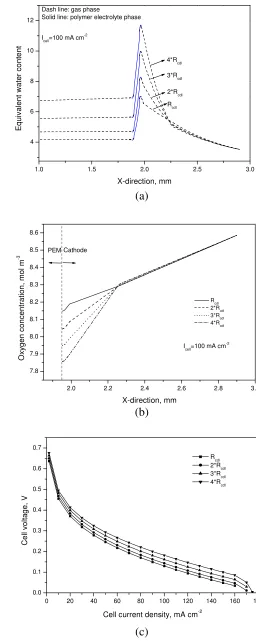
Fig. 15 Effect of the cathode GDLs with different mass-transfer
DOI: 10.5098/hmt.v2.3.2001 ISSN: 2151-8629 content in the anode CL is decreased from 4.2 to 2.7 when the Nafion
112 is replaced by Nafion 117. Such a decrease in the water content in the anode CL consequently increases the anode overpotential. In addition, as shown in Fig. 14c, an increase in the membrane thickness also leads to a decrease in the mean water content in the membrane, thus increasing the ohmic loss, which is proved by the experimental work discussed above. Another factor affects the cell performance is the mass-transfer resistance of the cathode GDL, the influence of which is shown in Fig. 15. It is seen that increasing the resistance of the GDL leads to an increase in the mean water content in the cathode CL, thereby increasing the mean water contents in both the membrane and the anode CL. As a result, both the anode overpotential and the ohmic loss decrease, which tends to improve the cell performance, as shown in Fig. 15c. However, it should be pointed out that increasing the resistance of the cathode GDL can also result in an increase in the transport resistance of oxygen from the ambient air to the cathode CL and thus in turn lowers the oxygen concentration in the cathode CL, which can be seen in Fig. 15b.
The above mathematical models of the DMFCs operating with concentrated fuel indicate that the mass transport and cell performance are influenced by the cell design and operating conditions. More importantly, it is further revealed that the methanol and water management are critically important for improving the cell performance of the DMFC at concentrated-methanol operation. Moreover, to obtain a deep understanding of the coupled heat and mass transport in the DMFCs at the neat-methanol operation, advanced models with consideration of the non-isothermal effect and the water effect on the anode MOR are needed.
8. CONCLUDING REMARKS
Operating DMFCs with concentrated fuel is desirable to maximize the specific energy and to improve the cell performance. As the mass transport mechanisms of reactants and products in DMFCs operating with concentrated fuel are different from those with diluted methanol solution, many unique challenging issues exist in the supply of the reactants and removal of the products. This review has given a comprehensive overview of recent experimental and numerical studies of mass transport in DMFCs fed with concentrated fuel. Emphasis is placed on the mechanisms and key issues of mass transport of each species, including mass transport of methanol, CO2, water and oxygen,
through the fuel cell structure under the operation with concentrated fuel. The recent investigations have laid a solid foundation for the basic understanding of how the design of different MEA components and flow fields as well as the operating conditions, affect cell performance, operating stability, and system specific energy. Nevertheless, more extensive work in this direction is needed and the future research in DMFCs operating with concentrated fuel should be directed to addressing the following critical issues.
1.For mass transport at the anode, attention needs to be paid to the understanding of the mechanisms of methanol transport in counter-convected and diffused CO2 in a porous electrode structure. In
addition, the efforts dealing with how the presence of liquid water in the anode affects the evaporation of methanol and its transport to the anode CL, should also be made.
2.With respect to water management, gaining deeper insights into the water transport in the anode and its influence on the anode MOR are needed. Moreover, to maximize the cell performance, more extensive work has to be undertaken to optimize the existing MEAs and develop new MEAs so that a sufficiently high mole ratio of water to methanol for the MOR can be achieved and the problem of cathode water flooding can be avoided.
3.For the oxygen transport at the cathode, the key issue is how to minimize both the concentration loss of oxygen and the water loss from the cathode.
4.In addition to mass transport, particular attention needs to be directed towards the thermal management to maintain an appropriate and
uniformly distributed operating temperature that can maximize the cell performance.
5.Finally, multi-scale, coupled heat and mass transport modeling that can simultaneously capture the detailed physical and electrochemical processes occurring inside the DMFC operating with concentrated fuel is needed.
ACKNOWLEDGEMENTS
The work described in this paper was fully supported by a grant from the Research Grants Council of the Hong Kong Special Administrative Region, China (Project No. 623010).
NOMENCLATURE
As,cl specific surface area (1/m) Av specific active surface area (1/m) C concentration (mol/m3)
D diffusivity (m2/s)
E correction factor
F Faraday constant (C/mol)
h interfacial transfer rate constant (m/s)
i current density (A/m2)
J molar flux (mol/m2·s)
j molar consumption (mol/m3·s)
Km permeability through the membrane (m2) MH2O molecular weight of water (kg/mol) n number of electron transfer
nd electro-osmotic drag coefficient
p pressure (Pa)
R universal gas constant (J/mol·K)
Ragg radius of the agglomerate (m)
T temperature (K)
Greek Symbols
α charge transfer coefficient
β reaction order
γ reaction order
δ thickness (m)
ε porosity
ϕ open ratio of the perforated plate
η overpotential (V)
ρ density (kg/m3)
µ viscosity (Pa·s)
Superscripts
eff effective property
ref reference condition
s dissolved
Subscripts
ACL anode catalyst layer
a anode
agg agglomerate
C convection
CCL cathode catalyst layer
c cathode
D diffusion
E electro-osmotic drag
g gas
M methanol
Mem membrane
MV methanol vapor
N Nafion
O2 oxygen