Research Journal
Volume 9, No. 27, Sept. 2015, pages 45–49
DOI: 10.12913/22998624/59083 Research Article
Received: 2015.06.05 Accepted: 2015.08.05 Published: 2015.09.01
BEAM–TO-COLUMN CONNECTION CALCULATIONS USING
ROBOT SOFTWARE
Mykhaylo Pashechko1, Anna Latos2
1 Department of Fundamentals of Technology, Lublin University of Technology, Nadbystrzycka 38 St., 20-618
Lublin, Poland, e-mail: [email protected]
2 Doctoral student at the Lublin University of Technology, e-mail: [email protected]
ABSTRACT
A beam–to-column connection design and results of engineer calculations using Au-todesk’s Robot Structural analysis are shown in the article. Two types of connections, bolted and welded, were calculated. The tensile resistance amounted to 912.74 kN, bending resistance to 100.87 kN·m and effective design capacity of the bolt amounted to 27.69 kN. Normal stress in the weld amounted to σ⊥max = τ⊥max = 72.72 MPa, in the vertical weld to σ⊥= τ⊥= 63.34 MPa and tangent stress amounted to τ|| = 4.37 MPa. The results allowed us to implement minor changes such as increasing the distance between the bolt and the edge and decreasing the size of the fillet welds. The design is fully compliant with the EN 1993-1-8 norm. Using Robot Structural Analysis substan-tially increased the pace of calculations giving precise and clear outcomes.
Keywords: structural connections, engineering calculations, robot software.
INTRODUCTION
Computer assistance in an engineer’s work is currently getting more effective and precise. The automation of the design process makes the time of project completion shorter and in-creases competitiveness of a product [3]. Au-todesk’s Robot Structural Analysis is one of the tools facilitating the work of designers and constructors [1, 3].
Autodesk Robot Structural Analysisis an in-tegrated graphic application used for modeling, analysis and dimensioning of various construc-tion types. The program features construcconstruc-tion design, carrying out static calculations of a
con-struction, outcomes verification, standardized cal -culations of construction elements and gathering documentation for calculated and dimensioned constructions. The most relevant features of the Robot include:
• a fully graphic definition of construction in the graphic editor (loading a DXF file containing
construction geometry prepared with a
differ-ent program is also possible).
• a possibility of a graphic representation of the designed construction as well as displaying various calculation outcomes (force,
displace-ment, multiple windows work etc.)
• calculation of the construction (dimensioning)
while designing another construction
(multi-threading),
• carrying out static and dynamic construction analyses,
• assigning the rod type while creating the con-struction model, not in standard modules.
• composing any type of print (calculation notes, screenshots, print composition,
export-ing objects to other programs) [1].
DESIGN OF CONSTRUCTIONAL
CONNECTION
parti-tions-ceilings and partition walls – are attached to the main constructional elements. The most commonly used connection types in multi-storey buildings are [2, 4, 5]:
• articulated nominal connections
(beam-to-beam and (beam-to-beam-to-column),
• moment connections (beam-to-column) in
case of continuous frames,
• bracings connections,
• column bases.
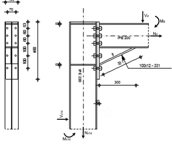
A type of beam-to-column constructional connection was designed using Robot Structural
Analysis software (Fig. 1). The column is an H-section of an IPE 220 profile and the beam of an IPE 200 profile. St3S steel was used in both parts.
Fig. 1. Beam-to-column connection model
The type of connection, material and profiles
geometry were chosen before the calculations. The parameters, e.g. forces and moments, can be
set automatically with possible manual modifica -tions in the edition mode.
For this particular connection bolted and welded connections were planned. There were
five rows and three columns of 10.9 grade bolds.
Filled welds of the following size were used: col-umn web weld aw = 4 mm, flange weld af = 7 mm, stiffener weld as = 4 mm and horizontal weld afd = 5 mm. The loads put on a beam-to-column con-nection:
• bending moment Md= 50 kN·m,
• shear force Vd = 10 kN,
• axial force Nd = 10 kN,
• bending moment in the lower column Mc1d= 50 kN·m,
• shear force in the lower column V c1d = 10 kN,
• axial force in the lower column N c1d = 10 kN. The sizes and loads in this particular project are presented in Figure 2.
ENGINEER CALCULATIONS OUTCOMES
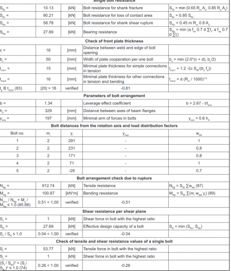
The next step using Robot Structural Analysis was to carry out engineer calculations and con-trol calculations to verify the bolt arrangements. Table 1 shows the outcomes of the calculations.
Next, calculation and verification of the used fillet
welds were performed. Table 2 shows the outcomes.
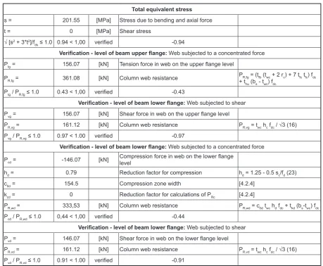
The last stage was to evaluate the forces and tension for frame corner and to verify the stabil-ity of the column web. Calculation outcomes are shown in Table 3. Tensile load resistance amount-ed to 912.74 kN and bending resistance to 100.87 kN·m. effective design capacity of the bolt calcu-lated by the program amounted to 27.69 kN.
Normal stress in a weld amounted to σ⊥max =
τ⊥max = 72.72 MPa, in the vertical weld to σ⊥ = τ⊥=
Table 1. Calculations outcomes and bolt arrangement control
Single bolt resistance
SRt = 10.13 [kN] Bolt resistance for shank fracture SRt = min (0.65 Rm As, 0.85 Re As) SRr = 90.21 [kN] Bolt resistance for loss of contact area SRr = 0.85 SRt
SRv = 58.78 [kN] Bolt resistance for shank shear rupture SRv = 0.45 m Rm 0.8 As
SRb = 27.69 [kN] Bearing resistance Sd ∑tRb = min (a fdc 0.7 d ∑ti, a fdp 0.7 i)
Check of front plate thickness
c = 16 [mm] Distance between weld and edge of bolt opening
bs = 50 [mm] Width of plate cooperation per one bolt bs = min (2.0*(c + d), bc/2)
tmin1 = 15 [mm] Minimal plate thickness for simple connections in tension tmin1 = 1.2 √(c SRt/(bs fd))
tmin2 = 16 [mm] Minimal plate thickness for other connections in tension and bending tmin2 = d (Rm / 1000)1/3
tp B tmin2 (83) |20| > 16 verified -0,81
Parameters of bolt arrangement
b = 1.34 Leverage effect coefficient b = 2.67 - t/tmin
h0 = 329 [mm] Distance between axes of beam flanges
ymin = 197 [mm] Minimal arm of forces in bolts ymin = 0.6 h0
Bolt distances from the rotation axis and load distribution factors
Bolt no. mi yi yired wtNi
1 2 291 - 1
2 2 231 - 0,8
3 2 171 - 0,8
4 2 71 - 1
5 2 -29 - 0.7
Bolt arrangement check due to rupture
NRjt = 912.74 [kN] Tensile resistance NRjt = SRt ∑wtNi (87) MRjt = 100.87 [kN*m] Bending resistance MRjt = SRt ∑(mi wtMi yi) (89) Nd(+) / NRjt + Md /
MRjt ≤ 1.0 (85.88) 0.51 < 1,00 verified -0,51
Shear resistance per shear plane
Sv = 1 [kN] Shear force in bolt with the highest ratio
SR = 27.69 [kN] Effective design capacity of a bolt SR = min (SRv, SRb) Sv / SR ≤ 1.0 0.04 < 1,00 verified -0.04
Check of tensile and shear resistance values of a single bolt
St = 53.77 [kN] Tensile force in bolt with the highest ratio Sv = 1 [kN] Shear force in bolt with the highest ratio (St / SRt)2 + (Sv/
SRv)2 ≤ 1.0 (74) 0.26 < 1.00 verified -0.26
63.34 MPa and tangent stress to τ|| = 4.37 MPa. Stress due to bending and axial force in the frame corner amounted to 201.55 MPa and Column web resistance to 116.12 kN.
All the outcomes are compliant with the EN
1993-1-8 norm. Minor constructional changes, such as increasing the distance between the bolt
and the edge and decreasing the size of the fillet
Table 2. Calculation outcomes and fillet weld control
Weld calculation
As = 59.6 [cm2] Area of all welds
Asx = 36.74 [cm2] Area of horizontal welds Asy = 22.86 [cm2] Area of vertical welds
Isx = 8903.77 [cm4] Moment of inertia of the weld arrangement with respect to the hor. axis ys = -80 [mm] Offset of weld centroid with respect to beam centroid
vyg = 183 [mm] Distance between upper weld edge and centroid of welds vyd = 164 [mm] Distance between lower weld edge and centroid of welds
c = 0.7 Resistance-dependent coefficient
s^max=t^max = 72.72 [MPa] Normal stress in a weld s^=t^ = 63.34 [MPa] Stress in a vertical weld
tII = 4.37 [MPa] Tangent stress
Weld check
c √[s^max2 + 3*(t^max2)] /
fdb ≤ 1.0 (93) 0.47 < 1,00 verified -0.47
c √[s^2 + 3*(t^2+tII2)] / fdb ≤ 1.0 (93)
0.41 < 1,00 verified -0.41
|s^| / fdb ≤ 1.0 (93) 0.34 < 1,00 verified -0.34
Table 3. Engineer and control calculation outcomes for frame corner and column web
Total equivalent stress
s = 201.55 [MPa] Stress due to bending and axial force
t = 0 [MPa] Shear stress
√ [s2 + 3*t2]/f
ds ≤ 1.0 0.94 < 1,00 verified -0.94
Verification - level of beam upper flange: Web subjected to a concentrated force Ptg = 156.07 [kN] Tension force in web on the upper flange level
PR,fg = 361.08 [kN] Column web resistance + tPR,fg = (tfb (twc + 2 rc) + 7 tfc tfc) fdc hu (bs - twc) fdc
Ptg / PR,fg ≤ 1.0 0.43 < 1,00 verified -0.43
Verification - level of beam lower flange: Web subjected to shear Pvg = 156.07 [kN] Shear force in web on the upper flange level
PR,vg = 161.12 [kN] Column web resistance PR,vg = twc hc fdc / √3 (16) Pvg / PR,vg ≤ 1.0 0.97 < 1.00 verified -0.97
Verification - level of beam lower flange: Web subjected to a concentrated force Pcd = -146.07 [kN] Compression force in web on the lower flange level
hd = 0.79 Reduction factor for compression hd = 1.25 - 0.5 sc/fd (23)
c0d = 154.5 Compression zone width [4.2.4]
kcd = 0 Reduction factor for calculations of PRc [4.2.4]
PR,wd = 333,53 [kN] Column web resistance PR,wd = c0d twc hd fdc + thd (bs-twc) fdc Pcd / PR,wd ≤ 1.0 0,44 < 1,00 verified -0.44
Verification - level of beam lower flange: Web subjected to shear Pvd = 146.07 [kN] Shear force in web on the lower flange level
CONCLUSIONS
Using Robot Structural Analysis for engineer calculations of beam-to-column connection type allowed us to evaluate bolted connection
resis-tance, calculation of weld stress and verification
of column web stability. All the outcomes were
verified. They are fully compliant with the design
and are resistant enough to the forces and mo-ments. Using computer software, through auto-mation, substantially increased the pace of work both while drawing the project and analyzing the data. Also, information about compliance with
the norm and fulfilling the assumed endurance
conditions was obtained.
REFERENCES
1. Autodesk. Podręcznik użytkownika. 2009, p. 3. 2. Poradnik architekta: Konstrukcje stalowe w
Eu-ropie cz.1. Opracowanie Arcelor Mittal, Peiner Trӓger, Corus, Wydawnictwo Elamed, 27–28. 3. Kubicki K. Free vibrations of frames and
their modeling in Autodesk Robot Structural Analysis program. Wydawnictwo Politechniki Częstochowskiej, Częstochowa 2012, p. 88.
4. Singer L.: Modern steel construction. „What’s cool in steel”, Sierpień 2009, p. 50.