The Use of a
Pneumatic Horizontal Impact System for
Helmet Testing
Leigh Jeffries, Carlos Zerpa*, Eryk Przysucha
,
Paolo Sanzo, Stephen CarlsonSchool of Kinesiology, Lakehead University, Thunder Bay, Canada
Abstract
Helmets are the main form of head protection used in the sport of hockey and have proven to be effective in minimizing linear accelerations applied to the head during impact. Unfortunately, head and brain injuries still continue to occur posing a significant threat to the health and safety of ice hockey players. The primary form of evaluating hockey helmets' performance is through the simulation of head impacts using impactors and anvils to measure acceleration during a free-fall mechanism. This method of assessment, however, does not closely emulate on ice head impacts to study injury mechanisms believed to be responsible for mild traumatic brain injuries and concussions. Based on this concern, there is a need to develop new impactors to further simulate and study mechanisms of injury in ice hockey. Evidence of reliability and validity for the use of these impactors’ acceleration measures is always needed before using these devices to accurately simulate head impact injuries and conduct further research. The purpose of this study was to provide evidence of reliability and validity for the use of a new pneumatic helmet impact system to measure horizontal linear impact acceleration before conducting helmet testing research. The results provide strong evidence of reliability (ICC = .79-.88, p < .0001) in measuring linear horizontal accelerations applied to the head across impact locations. The results also provide concurrent-related evidence of validity (ICC=.85-.95, p < .0001) when comparing the new pneumatic helmet impact system to a standardized drop head impact system. These outcomes suggest that the new impactor system can be used to accurately and consistently measure linear acceleration in future research.Keywords
Concussion, Helmet Impact System, Impact Biomechanics1. Introduction
Ice hockey is a high-speed collision sport with an inherent risk of injuries [1]. Most concerning of all injuries are the ones to the head and brain, which can lead to severe neurological dysfunction and even death [2]. Head injuries are commonly the result of traumatic brain injuries (TBI). A TBI is caused by a sudden impact causing acceleration-deceleration trauma of the head and may range from mild (mTBI) to severe [3]. Brain injuries can also be categorized as focal or diffuse. Focal brain injuries (e.g., skull fractures, hematomas), relate to damage to a specific location of the brain under the site of impact [4], resulting in focal neurological deficits specific to that area [5]. Diffuse head injuries (e.g., concussion), relate to damage to a more widespread or global disruption of neurological dysfunction and are not typically associated with macroscopically visible brain lesions [5]. Both types of injuries can possibly occur from a single impact.
* Corresponding author:
[email protected] (Carlos Zerpa)
Published online at http://journal.sapub.org/safety
Copyright © 2017 Scientific & Academic Publishing. All Rights Reserved
Helmets are the primary form of head and brain protection for hockey players to prevent injuries [2]. Research has shown that helmets have been effective in reducing head impact forces involved in skull fractures [6]. There is little evidence to support, however, that helmets are as effective at preventing mTBI or concussions from biomechanical forces applied to the head or torso [6]. One of the reasons may be that helmet designs and performance are being compromised for comfort and appearance [7].
Even with the mandatory wearing of helmets, head and brain injuries continue to increase in the sport of hockey. Concussions or mTBIs, for example, have been identified as one of the most common injuries in hockey with the highest occurrence per participant of all sports [8]. Recent concussion rates in ice hockey have been calculated to be 1.4 per 1000 player-games at the international [9] and collegiate levels [10]. This high rate of concussion injuries suggest that further development of helmet technology and testing protocols are needed.
respond similarly to an actual human head during impact [11]. Peak linear accelerations felt by the headform at impact are used to assess the ability of the helmet to protect the head against brain injuries and assess the injury risk [2, 12].
The maximum protocol value of linear acceleration allowed during helmet testing to protect the head against a brain injury is 275-300g from a drop height of 1.5 meters. This value was obtained from skull fracture data of human cadaver research and it is considered an acceptable threshold value to assess the pass or failure of a helmet [13]. If the peak linear acceleration value is less than the threshold value during the impact, the helmet is deemed appropriately protective. The unit “g”is used for any linear acceleration analysis and is a multiple of the acceleration due to gravity (g = 9.81m/s2).
While current standard helmet testing protocols entail the use of surrogate headforms instrumented with linear impact accelerometers and a free-falling drop mechanism (designed to strike a flat surface without head movement after impact), some injury mechanics in ice hockey occur horizontally with a head movement after impact [14]. In order to study injury mechanisms due to horizontal impacts, there is a need to develop impactors, instrumented with a headform free to move post impact to more closely emulate on ice hockey players' collisions [14]. This approach may provide an avenue to help improve hockey helmet testing standards and possibly reduce the risk of head injuries [13].
When introducing a new impactor and testing protocol to assess helmet performance, it is necessary to comply with the National Operating Committee on Standards for Athletic Equipment (NOCSAE) and provide evidence of reliability and validity for the use of the instrument measures [15]. Reliability refers to the consistency of a test or measurement measures across repeated trials [17]. The split-half method estimates reliability across repeated trials by creating two parallel subsets of equal size from one sample, then correlating even and odd scores to provide an estimate of the instrument’s reliability [16]. Validation of the instrument measures, on the other hand, can be obtained by providing concurrent-related evidence of validity. That is, the degree to which instrument measurements are correlated with another relevant instrument measure or standard as the primary test of interest [16]. Based on this premise, the purpose of this study was to provide evidence of reliability and validity for the use of a new pneumatic helmet impact system to measure horizontal linear impact acceleration to assess helmet performance.
2. Methods
2.1. Hypotheses used to Guide the Study
a) Evidence of reliability: It was hypothesized that there would be a strong correlation across trial replications on peak linear acceleration measures for each helmet impact
location.
b) Evidence of concurrent validity: It was hypothesized that there would be a strong correlation between the vertical and horizontal impactors’ linear accelerations measures across helmet locations when hit at the velocity of 4.39 m/s.
2.2. Instruments
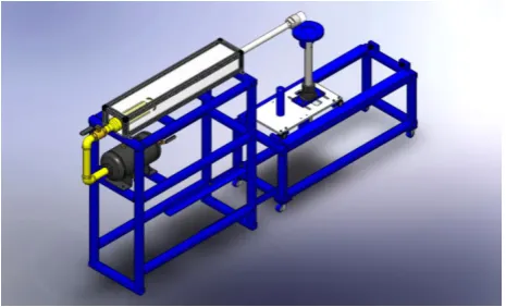
Pneumatic linear impactor used in this study. This
impactor consists of a main frame, impactor rod, and linear bearing table as depicted in Figure 1. The main frame is a welded steel structure secured to the floor. The main frame contains the compressed air tank, air cylinder, air release valve, impactor rod, and linear bearing table. The air cylinder propels the impact rod with velocities up to 7m/s by discharging the air pressure via a control valve from the 3-gallon compressed air tank. The air pressure is monitored using a MGA-100-A digital pressure gauge (SSI Technologies, Inc.) with an accuracy of ± 1%. The mass of the impacting rod is 13.1kg, and it is propelled horizontally when the compressed air is released. The head of the impacting rod consists of a 7.4cm (diameter) by 2.7cm (thick) cylindrical nylon pad attached to a 7.4cm long metal disc. This impactor head is slightly different than the impactor heads outlined by NOCSAE standards [18].
Figure 1. Schematic of the new pneumatic linear impactor
The linear bearing table contains an assembly attachment that is used to secure and position the surrogate headform in any specific head impact location. The linear bearing table also has a shuttle plate that is free to move backward a distance of 0.49m following impact. When an impact happens, the shuttle plate moves and gets stopped by rubber bumper blocks located at the end of the horizontal tracks.
The headform assembly attachment plate has five degrees of freedom movement to position the headform to specific impact locations. These degrees of freedom movement include: forward and backward (x), laterally (y), up-down (z), titling forward and backwards, and laterally rotating. Once adjustments are made, the headform gets secured and fixed to the desired head impact location.
56.1kg. For the purpose of this study, the table mass was kept at 46.6kg.
Drop system. A vertical dual rail drop system, as depicted
in Figure 2, was used as a standard to validate the linear impact acceleration measures obtained from the horizontal impactor when assessing helmet performance [11]. The vertical impact rig incorporates a drop carriage with a surrogate headform and neckform mounted on it. The drop carriage behaves as free falling when simulating head impacts. The weight of the headform, neckform, and drop carriage is 30.6kg and this weight remained the same throughout the entire testing procedures for this study. A 110-volt AC winch with a cable connected to a magnetic plate was used to elevate the drop rig to the predetermined height prior to each impact. The winch raised or lowered the drop rig by using a switch mounted on an electronic controller. When the magnetic plate was energized, it remained in contact with the steel drop carriage. As soon as a release switch on the electronic controller was pressed, the magnets were de-energized and the drop carriage fell freely onto a nylon impact anvil surface, very similar to the one on the horizontal impactor head. The anvil impact surface was mounted on a steel plate bolted into the floor. Before bolting the steel plate to the floor, a rubber mat spacer was placed between the steel plate and floor to minimize noise and vibration caused during impact.
Figure 2. Vertical dual rail drop system with headform mounted on drop carriage and positioned to contact the impact anvil
Headform. A medium sized NOCSAE headform, as
depicted in Figure 3, was used for all vertical and horizontal impact trials. The headform weighs 4.90kg and it is representative of a 50th percentile adult male head [19]. This
headform is also considered to be anatomically representative of a human head due to the inclusion of appropriate facial features and bone structure [7]. The NOCSAE headform is instrumented with a collection of accelerometers to measure the acceleration experienced in the anterior-posterior, superior-inferior, and left-right directions. This headform has been used in other published research studies to simulate the dynamic response of the human head during an impact including both linear and rotational accelerations [2].
Figure 3. NOCSAE headform fitted with hockey helmet and mounted on mechanical neckform
Mechanical neckform. The neckform, as depicted in
Figure 4, was designed to mimic a 50th percentile human
neck. It consists of four neoprene rubber discs fitted between circular steel discs with end plates at the top and bottom. To prevent displacement of the steel and rubber discs, the component materials have a protruded cylindrical offset allowing for the steel and rubber discs to be pressed tightly together. A top plate and base bracket secure all components together. The rubber discs were designed to mimic the loading response that a human neck would experience during a head impact.
Figure 4. Mechanical neckform assembly
Helmets. Two identical hockey helmets were used during
the impact testing. The helmets were fitted on the headform prior to each drop by following helmet fitting instructions as defined by the NOCSAE standards.
2.3. Procedures and Analyses
sustain higher average g-accelerations, and be linked to an increased risk of injury [20].
Before collecting helmet impact data from each vertical and horizontal impactor across the three impact sites, NOCSAE standards [12] were used to fit a hockey helmet to the surrogate headform. The helmet testing protocol was further standardized by ensuring a 5.5cm distance from the brim of the helmet to the bridge of the nose on the headform. The head was then positioned and secured to either the front, side, or rear impact location. To achieve the impacts on the new pneumatic linear impactor, the compressed air tank was pressurized to 40psi. Once the pressure was achieved, a manual control valve was open and the air pressure was released, propelling the impact rod into the impact site at an average speed of 4.39m/s. To achieve identical impacts when using the standardized vertical drop rig, the drop carriage was raised to a height of 0.98m and dropped onto the impact anvil.
For each impact location on the helmet, the linear acceleration data (x, y, and z directions) were acquired by the accelerometer sensors mounted in the headform. The data were fed into an analog to digital amplifier unit and processed via a commercial software package called POWERLAB.
Resultant linear acceleration was computed using the POWERLAB software calculation module based on Equation 1:
Resultant Acceleration = �x2+y2+z2 (1)
where:
x = linear acceleration in the x-direction y = linear acceleration in the y-direction z = linear acceleration in the z-direction
A 1000Hz low pass filter was implemented to minimize noise levels. The data were collected at a sampling rate of 20,000Hz for each acceleration input channel composed of 12-bit data. Each helmet location was tested in sequential order, ensuring that all impacts to each helmet were completed before moving to the next location. The order of the impacts was: front, rear, and side. For the reliability analysis, the helmets were subjected to 100 impacts for all locations using the horizontal linear impactor. For the validity measures, the helmet was impacted 25 times per location for each vertical and horizontal impactor.
Data were analysed using IBM® SPSS version 24. The
split-half method was used to examine the reliability of the peak linear acceleration measures obtained from the new pneumatic horizontal impactor for the front, rear, and side locations. This method is used when the results from a single measure are randomly divided into two equal halves. The two equal halves from the peak acceleration data obtained from this study were correlated using intraclass correlations to determine reliability of the scores across replications [16]. For the validity analysis, intraclass correlations were also used to compare the acceleration measures between the vertical and horizontal impactors across impact locations.
3. Results
3.1. ReliabilityThe results depicted in Table 1 provide a summary of the peak linear acceleration measures obtained from 100 impacts to the front, side, and rear locations when hit by the horizontal impactor rod propelled with a pressure of 40psi. The front location had the highest mean peak linear acceleration (M=97.29g, SD=5.72g) when compared to the side (85.67g, SD=5.75g) and rear (M=88.86g, SD=5.40g) locations. The results also provide evidence of reliability as strong significant intraclass correlation coefficients (ICC) were found across replications for the front (r=0.86, n=50), side (r=0.79, n=50), and rear (r=0.81, n=50) impact sites respectively.
Table 1. ICC for Peak Linear Acceleration across Impact Locations to Provide Evidence of Reliability
Location Mean (g) SD (g) ICC Sig. Front 97.29 5.72 .875 .0001
Side 85.67 5.75 .787 .0001 Rear 88.86 5.40 .809 .0001
3.2. Validity
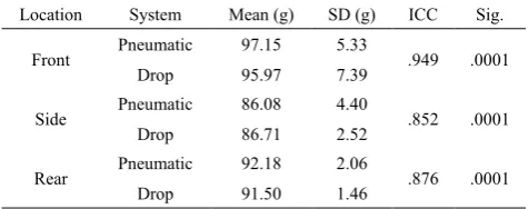
The results in Table 2 provide a summary of the mean peak linear acceleration measures across impact locations for the vertical and horizontal impactors when used under the same impact testing protocol. The results also provide evidence of concurrent-validity when comparing the acceleration measures of the new pneumatic linear horizontal impactor to the acceleration measures of the vertical standard drop system. This evidence of validation was revealed by strong significant intraclass correlations between the acceleration measures obtained from both systems on the side (r=0.85, n=25), front (r=0.95, n=25), and rear (r=0.88,
n=25) helmet impact locations.
Table 2. ICC for Peak Linear Acceleration across Impact Locations to Provide Evidence of Validity
Location System Mean (g) SD (g) ICC Sig.
Front Pneumatic 97.15 5.33 .949 .0001 Drop 95.97 7.39
Side Pneumatic 86.08 4.40 .852 .0001 Drop 86.71 2.52
Rear Pneumatic 92.18 2.06 .876 .0001 Drop 91.50 1.46
4. Discussion
side location when comparing the acceleration measures between the vertical and horizontal impacts. As stated in previous research [7], one of the reasons for this outcome, may be that the side location behaves differently in minimizing impact accelerations as compared to other helmet locations due to the geometry of the helmet. Human error can also play a role in reliability and validity measures as any small discrepancy in repositioning the helmet before each impact on the side location or any other helmet location can translate into a change in neck torque and, consequently, a change in linear impact acceleration. Human error was minimized in the current study by following the NOCSAE standards and using the same researcher to reposition the helmet before each impact. It is also important to consider that NOCSAE standards specify that pneumatic ram impactors can propel the impactor arm at ± 2% of the specified velocity, which can also translate into small but not significant differences on acceleration measures across replications and between impactors.
Reliability and validity measures could have also been affected by the use of a manual control valve to release the pressure and propel the horizontal impactor arm. Although the researcher who collected the data tried to open the valve consistently each time, there is still the possibility of additional human error being introduced in the measurement. Future research studies will include the use of an electronic solenoid valve. A solenoid valve is a device actuated by a solenoid, for controlling the flow of gases in pipes [21]. This device will automatically release the air pressure to propel the horizontal impactor arm to acquire higher consistency during data collection. Regardless of this limitation, the result indicate that the new horizontal impact system is comparable to a standard NOCSAE drop system when tested under the same impact protocol. This evidence of validation in combination with the reliability measures indicate that the system can be used for research on helmet impact testing. Future research will entail the use of this impactor to simulate and study head impact injury mechanisms and energy dissipation measures across helmet impact locations.
5. Conclusions
The purpose of this study was to provide evidence of reliability and validity for the use of a new pneumatic impactor when measuring peak linear acceleration. The findings of this study provide evidence that the new horizontal impactor acceleration measures are reliable and valid to conduct further research for helmet testing and simulated injury reconstruction in hockey or other sports. The outcomes may also have implications on helmet design and standards for impact testing.
ACKNOWLEDGMENTS
The researchers would like to thank the senior engineering students from the Mechanical Engineering Department at
Lakehead University for designing and building the impactors. The researchers would also like to thank Glen Patterson for his technical expertise in calibrating the impactors.
REFERENCES
[1] Agel, J., & Harvey, E. (2010). A 7-year review of men’s and women’s ice hockey injuries in the NCAA. Canadian Journal of Surgery, 53(5), 319-323.
[2] Post, A., Oeur, A., Hoskizaki, B., & Gilchrist, M. (2011). Examination of the relationship between peak linear and angular accelerations to brain deformation metrics in hockey helmet impacts. Computer Methods in Biomechanics and Biomedical Engineering, 16(5), 511-519.
[3] Centers for Disease Control and Prevention (CDC). (2003). Report to congress on mild traumatic brain injury in the United States: Steps to prevent a serious public health problem. Atlanta (GA): Centers for Disease Control and Prevention.
[4] Andriessen, T. M., Jacobs, B., & Vos, P. E. (2010). Clinical characteristics and pathophysiological mechanisms of focal and diffuse traumatic brain injury. Journal of Cellular and Molecular Medicine. 14(10), 2381-2392.
[5] Guskiewicz, K. M., & Mihalik, J. P., (2006). The biomechanics and pathomechanics of sports related concussion. In S. M. Slobounov & W. J. Sebastianelli (Eds.), Foundations of sports-related brain injuries (65-88). New York, NY: Springer Science + Business Media, Inc. [6] Kis, M., Saunders, F., Kis, M., Irrcher, I., Tator, C., Bishop, P.,
& Hove, M. (2013). A method of evaluating helmet rotational acceleration protection using a Kingston Impact Simulator (KIS unit). Clinical Journal of Sports Medicine, 23(6), 470-477.
[7] Zerpa, C., Carlson, S., Elyasi, S., Przyucha, E., & Hoshizaki, T. (2016). Energy dissipation measures on a hockey helmet across impact locations. Journal of Safety Engineering, 5(2), 27-35.
[8] Kelly, K., Lissel, H., Rowe, B., Vinventen, J., & Voaklander, D. (2001). Sport and recreation-related head injuries treated in the emergency department. Clinical Journal of Sports Medicine, 11(2), 77-81.
[9] Tuominen, M., Stuart, M., Aubry, M., Kannus, P., & Parkkari, J. (2015). Injuries in men’s international ice hockey: a 7-study of the International Ice Hockey Federation Adult World Championship Touraments and Olympic Winter Games. British Journal of Sports Medicine, 49 (1), 30-36.
[10] Agel, J., Dompier, T., Dick R., & Marshall, S. (2007). Descriptive epidemiology of collegiate men’s ice hockey injuries: National collegiate athletic association injury surveillance system, 1988-1989 through 2003-2004. Journal of Athletic Training, 42(2), 241-248.
Biomechanics in Sports, Tsukuba, Japan, July 18-22, 2016. [12] National Operating Committee on Standards for Athletic
Equipment. (2017). Standard Test Method and Equipment Used in Evaluating the Performance Characterizes of Headgear/Equipment: NOCSAE DOC ND 001-15m15b. Overland Park, USA: NOCSAE.
[13] Gurdjian, E., Roberts, V., Thomas, L. (1966). Tolerance curves of acceleration and intracranial pressure and protective index in experimental head injury. The Journal of Trauma, 6(5), 600-604.
[14] National Operating Committee on Standards for Athletic Equipment. (2006). Standard Linear Impactor Test Method and Equipment used in Evaluating the Performance Characteristics of Protective Headgear and Face Guards:
NOCSAE DOC (ND) 081-04m04. Overland Park, KS:
NOCSAE.
[15] Cronbach, L., & Meehl, P. (1955). Construct validity in psychological tests. Psychological Bulletin, 52(4), 281-302. [16] Furr, R., & Bacharach, V. (2008). Psychometrics: An
introduction. Thousand Oaks, CA: Sage Publications, Inc.
[17] Charkrabratty, S. N. (2013). Best split-half and maximum reliability. IOSR Journal of Research & Method in Education, 3(1), 01-08.
[18] National Operating Committee on Standards for Athletic Equipment. (2016). Standard Pneumatic Ram Test Method and Equipment used in Evaluating the Performance Characteristics of Protective Headgear and Face Guards: NOCSAE DOC (ND) 081-14m15. Overland Park, USA: NOCSAE.
[19] Hodgson, V. (1975). National Operating Committee on Standards for Athletic Equipment football certification program. Medicine and Science in Sports, 7(3), 225-232. [20] Walsh, E., Rousseau, P., & Hoshizaki, T. (2011). The
influence of impact location and angle on the dynamic impact response of a Hybrid III headform. Sports Engineering, 13(3), 135-143.