Please cite this article as: S. H. Mousavi Motlagh, K. Mazlumi, A Novel Objective Function for Directional Overcurrent Relays Coordination, TRANSACTIONS B: Applications Vol. 28, No. 2, (February 2015) 205-213
International Journal of Engineering
J o u r n a l H o m e p a g e : w w w . i j e . i rA Novel Objective Function for Directional Overcurrent Relays Coordination
S. H. Mousavi Motlagha,b, K. Mazlumi* a
aDepartment of Electrical Engineering, University of Zanjan, Zanjan, Iran b Zanjan Regional Electric Company, Zanjan, Iran
P A P E R I N F O
Paper history: Received 09 April 2014
Received in revised form 07 June 2014 Accepted 13 November 2014
Keywords: Relay Coordination Evolutionary Algorithms Objective Function Relay TMSs
A B S T R A C T
Directional overcurrent relays (DOCRs) are widely used to protect power systems. For optimal coordination of DOCRs, several techniques have been proposed to solve this problem. A common way of optimal coordination of DOCRs is using evolutionary algorithms such as genetic algorithm (GA). In this paper, a novel strategy for DOCRs coordination is proposed. In the proposed strategy, a new objective function (OF) is introduced. The proposed objective function can removed mis-coordination between paired relays and can result in better coordination. Proposed OF is applied to 6-bus and 30-bus sample networks.
doi: 10.5829/idosi.ije.2015.28.02b.06
1. INTRODUCTION1
Protection of distribution networks is one of the most important issues in power systems. Overcurrent relay is one of the most commonly used protective relays in these systems. There are two types of settings for these kinds of the relays: current and time settings. A proper relay setting plays a crucial role in reducing undesired effects of faults on the power systems [1, 2]. Overcurrent relays commonly have plug setting (PS) ranging from 50 to 200% in steps of 25%. The PS shows the current setting of the overcurrent relays. For an overcurrent relay, PS is defined by two parameters: the minimum fault current and the maximum load current. However, the most important variable in the optimal coordination of overcurrent relays is the time multiplier setting (TMS) [3]. So far, some research has been carried out on coordination of overcurrent relays [3-7]. Due to the difficulty of nonlinear optimal programming techniques, the usual optimal coordination of overcurrent relays is generally carried out by linear programming techniques, including simplex, two-phase simplex and dual simplex methods [3]. In these
11*Corresponding Author’s Email: [email protected](K. Mazlumi)
methods, the discrimination time of the main and backup relays (Dtmb) are considered as constraints and then the optimal coordination problem is solved using both OF and constraints. A fast method for optimization of the TMS’s and current settings by evolutionary algorithm and linear programming has been proposed by Sueiroet al. [8]. An online technique to estimate the setting of DOCRs is introduced in another literature [4]. This technique is based on the estimation of the parameters of a proper equivalent circuit of the network. In relay coordination, which is very constrained, the discrete optimization problem is hardly solved by traditional optimization techniques [5]. The pickup current and the TMS of the relays have been considered as the optimization parameters for optimal coordination of DOCRs by Ezzeddine et al. [9]. The linear programming optimization techniques are started by an initial conjecture and are possibly trapped in a local optimum [3]. The evolutionary optimization techniques have come up in such a way that can adjust the settings of the relays without the mentioned problems. In these methods, the constraints are considered as a part of OF. A developed method based on genetic algorithm (GA) for optimal coordination has been proposed [6]. This method does not resolve the mis-coordination between
the relays. As a result of the mis-coordination, when a fault occurs in front of the main relay, some backup relays may operate faster than the main one. This causes more lines of network go out due to the occurring faults in some parts of the network. Obviously, in this case, the number of interrupted customers increases and consequently the power quality declines. In other research [10], continuous genetic algorithm has been used in a ring fed distribution system for optimal coordination of overcurrent relays . An OF has been proposed in which the problem of mis-coordination have almost been resolved by Razavi et al. [11]. In their research [11], the OF can prevent the appearance of inappropriate results which make mis-coordination. The OF of Razavi et al. [11] consists of the three coefficients. The coefficients of the OF should be chosen very carefully. These coefficients determine the importance of the minimizing the operating time of the relays or the minimizing the time difference between the main and the backup relays. The main shortcoming of Razavi et al. [11] is that some of the coefficients of OF are set by try and error. It is proved by experience that using such coefficients cannot guarantee accessing to the smallest operation time of the relays. In some cases, using inappropriate parameters in OF may result in some mis-coordination.
In this paper, a new OF is proposed for DOCRs coordination that not only the mis-coordination is omitted but also the operating times of the relays are better than the existing methods. In the novel proposed OF, the number of the mis-coordination is considered as a part of OF. Since the proposed OF contains only one part, the OF do not need any weighting coefficients. The new OF is applied to 6-bus and 30-bus sample networks. The results of this OF are compared with the results of the existing ones. The simulation results and the comparisons demonstrate the effectiveness and the advantage of the proposed OF. Proposed OF for DOCRs coordination in this study is solved by GA.
2. APPLICATION OF GA IN RELAY COORDINATION
Evolutionary algorithms, such as GA, are used to solve complex optimization problems such as the relay coordination problem. GA is a heuristic method which is used to determine the best coordination of DOCRs. This algorithm has the strings called chromosome. A chromosome consists of the series of genes. The genes are the optimization problem variables which can be represented by binary or real codes. In DOCRs coordination problem, the genes of each chromosome are TMS's of the relays. GA generally includes three basic genetic operators of reproduction, crossover and mutation [12, 13]. In this section, we briefly discuss the application of the GA in DOCRs coordination. A simple flowchart for the GA is shown in Figure 1. The GA
concept in DOCRs coordination is described in 4 steps: Step 1: Initialization
In the first step, some randomly chromosomes are produced. In coordination problem, the number of the variables is equal to the number of the TMS's of the relays in which the TMS of the relays should be between 0.05 and 1. Suitable values of TMS's determine in the optimization process.
Step 2: Evaluation
In the second step, the value of the OF is calculated for every chromosome. The OF has a basic role to discern between good and bad chromosomes.
Step 3: Selection
In the third step, the chromosomes are compared with the best initial chromosome. The best chromosome is one in which the value of the TMSs are minimum. The best chromosomes are selected by the OF and pass to the next generation.
Step 4: Reproduction
In the last step, update the value of the genes by using the operators of reproduction (crossover and mutation). If the iterations reach to the specified value, the optimal TMSs of the relays are determined.
3. PROBLEM STATEMENT
The main aim of DOCRs coordination problem is to determine the TMS of each relay and minimizing the operating time of the main relays. On the other hand, the constraints must be regarded. A new OF has been proposed by Razavi et al. [11] to prevent DOCRs mis-coordination and to find the optimum results as follows:
å
å
+ D - D - D= 2
2 2
1 ( ) ( ( ))
.F ti tmb tmb tmb
O a a b (1)
where, α1, α2 and β are weighting coefficients;
t
i is the operating time of the i-th overcurrent relay when a fault occurs next to the relay;D
t
mb is the discrimination time between the main and backup overcurrent relays. In DOCRs coordination, the constraints are defined based onDtmb:CTI t t
tmb = b - m
-D (2)
The first term of Equation (1) is the sum of overcurrent relays operating time when a fault occurs next to the relays and the second term is the coordination constraint. To minimize the main relays operating time, a great value must be assigned to α1. To emphasis on minimizing the backup relay operating time, a large value must be assigned to α2. To prevent mis-coordination, a large value for β is chosen.
The main problem of the OF of Razavi et al. [11] is that it consists of two terms. In multi term OFs, the weighting coefficients is necessary to define according to the importance of each term in OF and have important role in the optimization [15]. The weighting coefficients must be chosen according to the importance of each term [16]. The proposed OF of Razavi et al. [11] is not very satisfactory for several reasons:
v On the one hand, the selection of the weighting coefficients is very difficult, because both terms have equal importance and setting them by try and error cannot guarantee accessing to the smallest operating time of the relays.
v On the other hand, since different weighting coefficients make search space very widespread, obtaining the optimal solution is almost impossible.
v By increasing the negative value of
D
t
mb, the cost of the OF increases. This means that the small negativeD
t
mb's may be accepted as a result of the optimization because these values do not increase the OF value very much. According to the above discussion, Razavi et al. [11], the three weighting coefficients (β, α1, α2) must be set by try and error. Therefore, the proposed OF of Razavi et al. [11] cannot guarantee obtaining the best coordination and the smallest operating time of the relays. To resolve this problem, a new technique should be employed in which the terms of the OF are not stated separately. Therefore, the new technique does not need weighting coefficients. In this paper, we will introduce a novel OF, in section 4, that resolve the mentioned problems of OF of Razavi et al. [11].4. NEW OBJECTIVE FUNCTION
According to the previous sections, a new OF is proposed to obtain the best solution for DOCRs coordination problem. The proposed OF optimizes the TMS’s of the relays in order to have a fast operating time and preventing relay mis-coordination. The new OF is as follows:
) 1 (
1
.
+
=
÷ ø ö ç è æ =
å
NMC n
i i
t F
O (3)
where n is the number of the relays;
t
i is the operating time of DOCRs when a fault occurs next to the ith relay. NMC is an index that shows the total number of mis-coordination i.e., NMC is the summation of the number of the negativeDtmb's. To satisfy the constraints, they are included in the OF. Equation (3) consists of two terms; the first term is(
( ))
1å
ti that minimizes the value of the TMS's; and the second term is(
( ))
NMCi
t
å
whichindicates the constraints and eliminates the mis-coordination. The OF is obtained by multiplying the two mentioned terms (
(
( ))
1å
ti ×(
( ))
NMC i t
å
=(
( )
)
+1å
NMCi
t ).
Therefore, if a constraint is not satisfied, NMC would be large and the cost of the OF is increased. So, to minimize the OF, the GA does not select the solution with unsatisfied constraints. For each negative value of
mb
t
D , the OF is large even when Dtmb is small and negative. For the proposed OF of this paper, there is no difference between small and large negative values of
mb
t
D .
The performance of the new OF relies on the minimization of the relays operating time with respect to the total number of mis-coordination (NMC); in which the number of the mis-coordination should be minimized. The formulation of OF shows that the optimal solution is achieved when the value of NMC is zero.
The advantage of this OF is that the shortcomings related to OF of Razavi et al. [11], determination of the weighting coefficients, are resolved.
5. MATHEMATICAL OVERCURRENT RELAY MODEL
There are many mathematical models for the overcurrent relays. In this study, the mathematical model of overcurrent relays is considered to be the standard inverse type. In this mathematical model, the operating time of the overcurrent relay is as follows [17]:
1
0
-÷÷ ø ö çç è æ
´
= n
sc
i i
TMS k t
(4)
6. RESULTS AND DISCUSSION
As described in section 4, the results of the optimization problem are TMS's. Therefore, the OF value is not suitable for comparing the results of the new OF with the OF of Razavi et al. [11]. In order to compare the results of the proposed OF and the OF of Razavi et al. [11], the following indices are defined:
v Summation of TMS’s: If there is no mis-coordination in the mis-coordination results, it can be said that the better coordination has smaller summation of TMS’s.
v Summation ∑
D
t
mb's: To compare two sets of the coordination results, for example set A and set B, which do not have any mis-coordination, if Equation (5) is true, the set of results of set A is better than set B.å
=
á D -D
n
mb mb A mb B
t t
1 ) (
,
, ) 0
( (5)
where, n is the number of relay main/backup (m,b) pairs of relays.
In Iran, almost all of the distribution networks are radial, but in other contries there are many interconnected or ring networks. Since applying the proposed method to the radial networks is so simple, in this paper we are applying this method to the interconnected network. The proposed OF is applied to two different networks. Case study 1 is a sample 6-bus network and case study 2 is a sample IEEE 30-bus network.
6. 1. Case Study 1 The network of Case study 1 is shown in Figure 2. This network is consists of 7 lines, 6 buses, 2 Generators, 2 transformers, and 14 overcurrent relays [18]. All the information about this network including short circuit currents of backup and main relays has been provided by Razavi et al. [11]. The way of the relay current settings described in (6) [11]:
max 0 1.2 il
i = ´ (6)
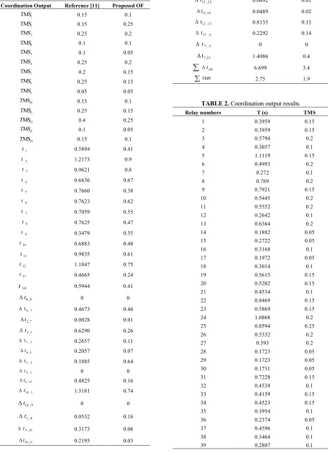
In this case study, the number of the genes is 14. The results of the proposed OF and the best results of Razavi et al. [11] are compared in Table 1. In this table, the second column shows the results of Razavi et al. [11], and the third column shows the results of the proposed OF. Also, in this table, the first 14 rows show the TMS of the relays. The second 14 rows show the operating time of the relays when a fault occurs next to the relays. In addition, Dtmb's are calculated according to Equation (2), where in this paper CTI is considered to be 0.3s. For example, Dt7,13shows the time difference between operating time of relay 13 and relay 7 when a fault
occurs next to the relay 7. The last two rows are provided to compare the results of the two OF. ∑Dtmb
shows the summation of the Dtmb's for each OF and in the last row of the table, ∑TMS shows the summation of the TMS's of the relays for each OF.
According to Table 1, all of the Dtmb's for the two
OF are positive values. Also, it is shown that the largest value of the Dtmb's for the OF of Razavi et al. [11] is 1.4086s and the largest value of the Dtmb's for the proposed OF is 0.74s. To complete the comparisons, it is shown that the value of the ∑
D
t
mb for the OF of Razavi et al. [11] and the proposed OF is, respectively, 6.699 and 3.4s. It is obvious that the proposed OF results in the smaller value of ∑D
t
mb with respect to the previous works. Moreover, the ∑TMS of the OF of Razavi et al. [11] and the proposed OF are 2.75 and 1.9, respectively. This shows that the operating time of the proposed OF is much better than the OF of Razavi et al. [11]. According to Table 1, most of the operating time of the relays obtained from the proposed OF are smaller than the values obtained from the OF of Razavi et al. [11]. For example, t12 obtained from the proposed OF is 0.75s whereast
12 obtained from the OF of Razavi et al. [11] is 1.1847s.
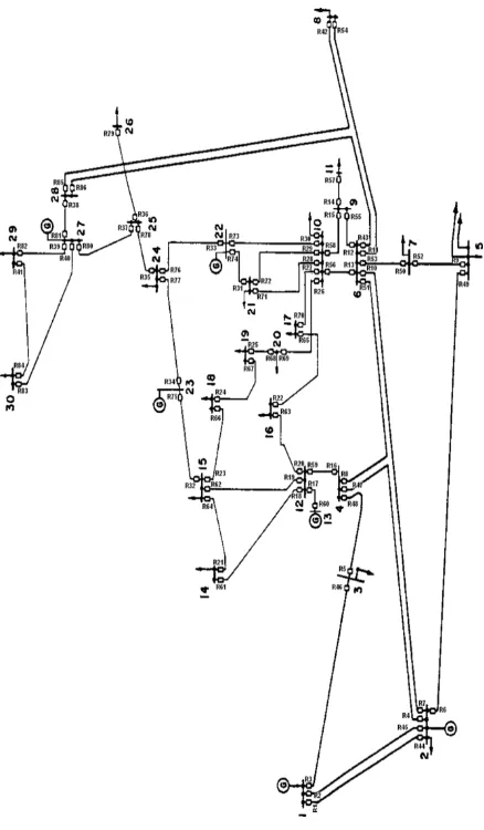
6. 2. Case Study 2 To have another case study, the 30-bus IEEE sample network is considered. It consists of 30 buses (132- and 33-kV buses), 37 lines, 6 generators, 4 transformers, and 86 DOCRs [19]. Figure 3 shows the single line diagram of the second case study [20]. The information of the generators, transmission lines, and transformers is taken from12.
In this paper, four different cases are simulated in order to have a better comparison. Three cases are simulated according to the OF of Razavi et al. [11] in which the OF coefficients are set manually. The last case is simulated according to the proposed OF of this paper.
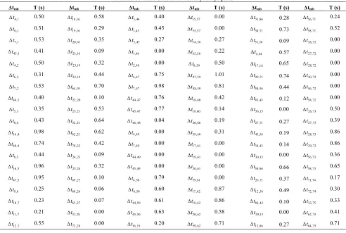
The results obtained from the proposed OF by GA (the fourth case) are shown in Tables 2 and 3. For simplicity, the results of the first three cases are not shown in this paper, but the comparisons are provided according to the results of the simulations. The first column of Table 2 shows relay number, the second column shows relay operating time for a fault next to the circuit breaker of each relay and the third column indicates the TMS of the relays. From Table 2, allDtmb's are positive numbers. The positive values ofD
t
mb's show that there is no mis-coordination in the results. Forexample, Dt4,1 refers to the relay pairs 4 and 1 that is 0.5s.
In the network all of the loads are considered to be the static loads. Therefore, in accordance to this fact that all of the relays are directional, the relays 57 and 79 in network of Figure 3 are not needed to be considered. So, in this study, the TMS's of these relays are set to be 0.05 [21, 22]. Of course, the other TMS's of the relays should be calculated by the coordination optimization problem.
Figure 1. Flowchart of GA
Figure 2. Case study 1
Figure 3. IEEE 30-bus system
In Table 4, the results of the simulations for the four cases are illustrated. In this table, the first row shows the four different cases; and the second and the third rows show the results of the ∑Dtmb's and ∑TMS's for these cases, respectively. The three first cases are related to the OF of [11] and the last case shows the results of the proposed OF. The values of the coefficients of the OF of [11] are shown in the first row of the Table 4. The values ofDtmb's in all cases are positive and have no mis-coordination. The advantage of the proposed OF is revealed when the results of case 4 are compared with the best results of the traditional OF of [11].
According to Table 4, the best ∑TMS and ∑Dtmb for OF of [11] (between three cases 1, 2 and 3) are 20.75 and 110.3416s, respectively. Whereas ∑TMS and ∑
mb t
D of the proposed OF are 10.3 and 72.36s,
TABLE 1. The coordination results
Proposed OF Reference [11]
Coordination Output
0.1 0.15
1 TMS
0.25 0.35
2 TMS
0.2 0.25
3
TMS
0.1 0.1
4 TMS
0.05 0.1
5
TMS
0.2 0.25
6
TMS
0.15 0.2
7
TMS
0.15 0.25
8
TMS
0.05 0.05
9
TMS
0.1 0.15
10
TMS
0.15 0.25
11 TMS
0.25 0.4
12 TMS
0.05 0.1
13
TMS
0.1 0.15
14 TMS
0.41 0.5894
1 t
0.9 1.2173
2 t
0.8 0.9621
3 t
0.67 0.6636
4 t
0.38 0.7660
5 t
0.62 0.7623
6 t
0.55 0.7059
7 t
0.47 0.7625
8 t
0.35 0.3479
9 t
0.48 0.6883
10 t
0.61 0.9835
11 t
0.75 1.1847
12 t
0.24 0.4665
13 t
0.41 0.5944
14
t
0 0
9 , 8 t
D
0.46 0.4673
7 , 8 t D
0.01 0.0028
7 , 2 t D
0.26 0.6290
1 , 2 t D
0.11 0.2657
2 , 3 t
D
0.07 0.2057
3 , 4
t
D
0.64 0.1885
4 , 5
t
D
0 0
5 , 6
t
D
0.16 0.4825
14 . 6 t
D
0.74 1.3181
1 , 14 t D
0 0
9 , 14 t
D
0.16 0.0532
6 , 1 t
D
0.06 0.3173
10 , 9
t
D
0.03 0.2195
11 , 10 t D
0.01 0.0492
12 , 11 t
D
0.02 0.0489
14 , 12 t D
0.13 0.8135
13 , 12 t D
0.14 0.2292
8 , 13 t D
0 0
5 , 7 t
D
0.4 1.4086
13 , 7 t
D
3.4 6.699
å
Dtmb1.9 2.75
åTMS
TABLE 2. Coordination output results
TMS T (s)
Relay numbers
0.15 0.3959
1
0.15 0.3959
2
0.2 0.5794
3
0.1 0.3057
4
0.15 1.1119
5
0.2 0.4993
6
0.1 0.272
7
0.2 0.769
8
0.15 0.7921
9
0.2 0.5445
10
0.2 0.5552
11
0.1 0.2642
12
0.2 0.6364
13
0.05 0.1882
14
0.05 0.2722
15
0.1 0.3168
16
0.05 0.1972
17
0.1 0.3014
18
0.15 0.5615
19
0.15 0.5202
20
0.1 0.4534
21
0.15 0.8469
22
0.15 0.5869
23
0.2 1.0868
24
0.25 0.8594
25
0.2 0.5332
26
0.2 0.593
27
0.05 0.1723
28
0.05 0.1723
29
0.05 0.1731
30
0.15 0.7228
31
0.1 0.4539
32
0.15 0.4159
33
0.15 0.4523
34
0.1 0.3954
35
0.05 0.2374
36
0.1 0.4596
37
0.1 0.3464
38
0.1 0.2807
TMS T (s) Relay numbers 0.1 0.2382 40 0.1 0.4934 41 0.15 0.3568 42 0.2 0.5248 43 0.15 0.4146 44 0.15 0.4 45 0.05 0.2424 46 0.1 0.3135 47 0.15 0.4608 48 0.05 0.2504 49 0.1 0.2913 50 0.2 0.618 51 0.1 0.3945 52 0.15 0.7155 53 0.05 0.2985 54 0.05 0.2311 55 0.15 0.6103 56 0.1 0.3447 58 0.1 0.3988 59 0.15 0.5391 60 0.05 0.2447 61 0.1 0.4998 62 0.1 0.5979 63 TMS T (s) Relay numbers 0.05 0.2146 64 0.15 0.566 65 0.1 0.5287 66 0.1 0.5888 67 0.2 0.9227 68 0.1 0.5355 69 0.15 0.8657 70 0.1 0.2904 71 0.05 0.1645 72 0.1 0.2942 73 0.2 0.6378 74 0.15 0.4821 75 0.15 0.6786 76 0.1 0.39 77 0.15 0.5789 78 0.15 0.4741 80 0.05 0.1763 81 0.05 0.2776 82 0.05 0.2293 83 0.05 0.3302 84 0.15 0.3632 85 0.1 0.4487 86
TABLE 3.Time difference for any relays pairs
T (s)
Δtmb
T (s)
Δtmb
T (s)
Δtmb
T (s)
Δtmb
T (s)
Δtmb
T (s)
Δtmb
TABLE 3. Continued
T (s)
Δtmb
T (s)
Δtmb
T (s)
Δtmb
T (s)
Δtmb
T (s)
Δtmb
T (s)
Δtmb
0.68 76 , 73 t D 0.59 70 , 58 t D 0.79 63 , 17 t D 0.20 51 , 47 t D 0.00 29 , 31 t D 0.13 7 , 13 t D 0.30 76 , 74 t D 0.16 56 , 11 t D 0.73 63 , 18 t D 0.04 51 , 48 t D 0.00 29 , 71 t D 0.24 7 , 43 t D 0.09 77 , 75 t D 0.22 42 , 38 t D 0.43 63 , 19 t D 0.10 52 , 49 t D 0.00 30 , 33 t D 0.15 7 , 51 t D 0.08 78 , 76 t D 0.00 15 , 28 t D 0.62 63 , 59 t D 0.27 53 , 11 t D 0.00 30 , 74 t D 0.19 8 , 10 t D 0.00 78 , 77 t D 0.70 86 , 12 t D 0.00 64 , 61 t D 0.59 53 , 12 t D 0.22 31 , 33 t D 0.17 8 , 11 t D 0.00 79 , 37 t D 0.31 70 , 56 t D 0.20 65 , 63 t D 0.19 53 , 13 t D 0.35 31 , 73 t D 0.48 8 , 12 t D 0.38 79 , 78 t D 0.18 56 , 10 t D 0.09 66 , 32 t D 0.30 53 , 43 t D 0.26 32 , 34 t D 0.09 8 , 13 t D 0.69 80 , 36 t D 0.47 41 , 83 t D 0.04 66 , 62 t D 0.57 53 , 50 t D 0.35 33 , 35 t D 0.20 8 , 43 t D 0.34 80 , 78 t D 0.00 15 , 27 t D 0.34 66 , 64 t D 0.21 53 , 51 t D 0.34 33 , 77 t D 0.46 8 , 50 t D 0.00 81 , 85 t D 0.38 86 , 11 t D 0.00 67 , 66 t D 0.00 54 , 10 t D 0.71 34 , 35 t D 0.26 9 , 53 t D 0.00 81 , 86 t D 0.77 70 , 30 t D 0.21 68 , 67 t D 0.00 54 , 12 t D 0.40 34 , 76 t D 0.16 10 , 52 t D 0.00 82 , 40 t D 0.00 55 , 51 t D 0.08 69 , 27 t D 0.00 54 , 13 t D 0.80 35 , 36 t D 0.09 11 , 42 t D 0.00 82 , 80 t D 0.55 40 , 84 t D 0.51 69 , 28 t D 0.00 54 , 43 t D 0.54 35 , 37 t D 0.29 12 , 14 t D 0.00 82 , 81 t D 0.00 15 , 26 t D 0.51 69 , 29 t D 0.00 54 , 50 t D 0.08 37 , 39 t D 0.19 12 , 15 t D 0.00 83 , 39 t D 0.37 86 , 10 t D 0.51 69 , 30 t D 0.00 54 , 51 t D 0.13 37 , 40 t D 0.13 13 , 26 t D 0.00 83 , 80 t D 0.76 70 , 29 t D 0.05 69 , 56 t D 0.00 55 , 10 t D 0.17 37 , 81 t D 0.06 13 , 27 t D 0.00 83 , 81 t D 0.00 55 , 50 t D 0.33 69 , 58 t D 0.00 55 , 11 t D 1.00 38 , 39 t D 0.49 13 , 28 t D 0.17 84 , 82 t D 0.68 39 , 41 t D 0.43 70 , 26 t D 0.00 55 , 13 t D 1.12 38 , 40 t D 0.49 13 , 29 t D 0.29 85 , 54 t D 0.31 13 , 58 t D 0.76 70 , 28 t D 0.00 55 , 43 t D 0.71 38 , 80 t D 0.49 13 , 30 t D
TABLE 4. Compartion beetwen proposed OF and OF of Razavi et al. [11]
(Case 1) β =100a1=1a2=100 (Case 2) β =1000a1=10 a2=5 (Case 3) β =500 a1 =1a2 =1 (Case 4) New OF
å
Dtmb 125.011 115.4904 110.3416 72.36å
TMS 34.45 20.75 28.1 10.37. CONCLUSION
In this paper, a new flexible method for overcurrent relays coordination has been proposed. In this method, a new useful OF has been introduced which is not dependent on the value of time differences of the relay pairs. The proposed OF of this paper, is dependent on the number of the mis-coordination. The proposed OF is solved by GA. This proposed method was tested on 6-bus and 30-6-bus IEEE case studies. The results of the simulations show the flexibility of the proposed OF and the best reliability because of the smaller ∑TMS and ∑
mb
t
D compared to the conventional coordination methods.
8. REFERENCES
1. Jannatian, M., Karegar, H.K., Askarian Abyaneh, H., Heidari, G. and Al-Dabbagh, M., "A novel fuzzy and artificial neural
network representation of overcurrent relay characteristics",
International Journal of Engineering, Transaction B: Applications, Vol. 16, No. 3, (2003), 233-246.
2. Askarian Abyaneh, H., Razavi, F., Al-Dabbagh, M., Karegar, H.K. and Jannatian, M., "A novel fuzzy and artificial neural network representation of overcurrent relay characteristics",
International Journal of Engineering, Transaction B: Applications, Vol. 16, No. 2, (2003), 133-142.
3. Birla, D., Maheshwari, R.P. and Gupta, H.O., "Time-overcurrent relay coordination: A review", International Journal of Emerging Electric Power Systems, Vol. 2, No. 2, (2005). 4. Ojaghi, M., Sudi, Z. and Faiz, J., "Implementation of full
adaptive technique to optimal coordination of overcurrent relays", Power Delivery, IEEE Transactions on, Vol. 28, No. 1, (2013), 235-244.
5. So, C. and Li, K., "Overcurrent relay coordination by evolutionary programming", Electric Power Systems Research, Vol. 53, No. 2, (2000), 83-90.
6. So, C., Li, K., Lai, K. and Fung, K., "Application of genetic algorithm for overcurrent relay coordination", (1997).
8. Sueiro, J.A., Diaz-Dorado, E., Míguez, E. and Cidras, J., "Coordination of directional overcurrent relay using evolutionary algorithm and linear programming", International Journal of Electrical Power & Energy Systems, Vol. 42, No. 1, (2012), 299-305.
9. Ezzeddine, M. and Kaczmarek, R., "A novel method for optimal coordination of directional overcurrent relays considering their available discrete settings and several operation characteristics",
Electric Power Systems Research, Vol. 81, No. 7, (2011), 1475-1481.
10. Bedekar, P.P. and Bhide, S.R., "Optimum coordination of overcurrent relay timing using continuous genetic algorithm",
Expert Systems with Applications, Vol. 38, No. 9, (2011), 11286-11292.
11. Razavi, F., Abyaneh, H.A., Al-Dabbagh, M., Mohammadi, R. and Torkaman, H., "A new comprehensive genetic algorithm method for optimal overcurrent relays coordination", Electric Power Systems Research, Vol. 78, No. 4, (2008), 713-720. 12. Rashtchi, V., Shabani, A. and Bagheri, A., "Optimal design of
measurement-type current transformer using genetic algorithm", in Power and Energy Conference, 2008. PECon 2008. IEEE 2nd International, IEEE, (2008), 958-961.
13. Ghiasi, M., Rashtchi, V. and Hoseini, S., "Optimum location and sizing of passive filters in distribution networks using genetic algorithm", in Emerging Technologies, 2008. ICET 2008. 4th International Conference on, IEEE, (2008), 162-166.
14. Lee, H.-J., Son, G. and Park, J.-W., "Study on wind-turbine generator system sizing considering voltage regulation and overcurrent relay coordination", Power Systems, IEEE Transactions on, Vol. 26, No. 3, (2011), 1283-1293.
15. Haupt, R.L. and Haupt, S.E., "Practical genetic algorithms, John Wiley & Sons, (2004).
16. Petrowski, J.D.A. and Taillard, P.S.E., Metaheuristics for hard optimization, (2006), Springer.
17. Amraee, T., "Coordination of directional overcurrent relays using seeker algorithm", Power Delivery, IEEE Transactions on, Vol. 27, No. 3, (2012), 1415-1422.
18. Bedekar, P.P. and Bhide, S.R., "Optimum coordination of directional overcurrent relays using the hybrid ga-nlp approach",
Power Delivery, IEEE Transactions on, Vol. 26, No. 1, (2011), 109-119.
19. Chabanloo, R.M., Abyaneh, H.A., Kamangar, S.S.H. and Razavi, F., "Optimal combined overcurrent and distance relays coordination incorporating intelligent overcurrent relays characteristic selection", Power Delivery, IEEE Transactions on, Vol. 26, No. 3, (2011), 1381-1391.
20. Sharifian, H., Askarian Abyaneh, H., Salman, S., Mohammadi, R. and Razavi, F., "Determination of the minimum break point set using expert system and genetic algorithm", Power Delivery, IEEE Transactions on, Vol. 25, No. 3, (2010), 1284-1295. 21. Slade, P., Wu, J., Stacey, E., Stubler, W., Voshall, R., Bonk, J.,
Porter, J. and Hong, L., "The utility requirements for a distribution fault current limiter", Power Delivery, IEEE Transactions on, Vol. 7, No. 2, (1992), 507-515.
22. Kumara, J., Atputharajah, A., Ekanayake, J. and Mumford, F., "Over current protection coordination of distribution networks with fault current limiters", in Power Engineering Society General Meeting. IEEE, Vol. 5, (2006). 113-121.
A Novel Objective Function for Directional Overcurrent Relays Coordination
S. H. Mousavi Motlagha,b, K. Mazlumia
aDepartment of Electrical engineering, University of Zanjan, Zanjan, Iran b Zanjan Regional Electric Company, Zanjan, Iran
P A P E R I N F O
Paper history: Received 09 April 2014
Received in revised form 07 June 2014 Accepted 13 November 2014
Keywords: Volatile Matter Devolatilizaiton Non-isothermal Reduction Iron Oxide
Non-coking Coal
هﺪﯿﮑﭼ
ﺪﻧﺮﯿﮔﯽﻣراﺮﻗهدﺎﻔﺘﺳادرﻮﻣترﺪﻗيﺎﻫﻪﮑﺒﺷردﯽﻌﯿﺳورﻮﻄﺑ،رادﺖﻬﺟدﺎﯾزنﺎﯾﺮﺟيﺎﻫﻪﻟر
.
ﻪﻟرﻪﻨﯿﻬﺑﯽﮕﻨﻫﺎﻤﻫياﺮﺑ يﺎﻫ
ﺖﺳاهﺪﺷدﺎﻬﻨﺸﯿﭘﯽﺗوﺎﻔﺘﻣيﺎﻫشوررادﺖﻬﺟدﺎﯾزنﺎﯾﺮﺟ
.
زاهدﺎﻔﺘﺳا،ﺎﻫﻪﻟرﻦﯾاﯽﮕﻨﻫﺎﻤﻫياﺮﺑمﻮﺳﺮﻣيﺎﻫشورزاﯽﮑﯾ
ﺪﺷﺎﺑﯽﻣﮏﯿﺘﻧژﻢﺘﯾرﻮﮕﻟاﺪﻨﻧﺎﻣﯽﻋﻮﻨﺼﻣشﻮﻫيﺎﻫﮏﯿﻨﮑﺗ
.
دﺎﯾزنﺎﯾﺮﺟيﺎﻫﻪﻟرﯽﮕﻨﻫﺎﻤﻫياﺮﺑيﺪﯾﺪﺟشور،ﻪﻟﺎﻘﻣﻦﯾارد
ﺖﺳاهﺪﺷدﺎﻬﻨﺸﯿﭘ
.
يدﺎﻬﻨﺸﯿﭘشورﻦﯾارد دﻮﺷﯽﻣﯽﻓﺮﻌﻣﺪﯾﺪﺟﯽﻓﺪﻫﻊﺑﺎﺗ
.
ﯽﮕﻨﻫﺎﻤﻫﺎﻧﺪﻧاﻮﺗﯽﻣﺪﯾﺪﺟيدﺎﻬﻨﺸﯿﭘفﺪﻫﻊﺑﺎﺗ
دﻮﺷﺎﻫنآنﺎﯿﻣيﺮﺘﻬﺑﯽﮕﻨﻫﺎﻤﻫﺐﺟﻮﻣوهدﺮﮐفﺬﺣارﺎﻫﻪﻟرجوزنﺎﯿﻣﺎﻫ
.
يﺎﻫﻪﮑﺒﺷرديدﺎﻬﻨﺸﯿﭘفﺪﻫﻊﺑﺎﺗ
6
و
30
ﺖﺳاهﺪﺷﻪﺘﻓﺮﮔرﺎﮑﺑﻪﺳﺎﺑ
.
![TABLE 4. Compartion beetwen proposed OF and OF of Razavi et al. [11]=α =α =α =](https://thumb-us.123doks.com/thumbv2/123dok_us/228689.2017429/8.595.59.542.103.417/table-compartion-beetwen-proposed-razavi-et-al-a.webp)
