Please cite this article as: H. Golbakhshi, M. Namjoo, E. Raeisi Estabragh, Evaluating the Effects of Ceramic Layer and Thermal Dam on Optimising the Temperature Gradient of a Gasoline Engine Piston, International Journal of Engineering (IJE), TRANSACTIONS A: Basics Vol. 28, No. 10, (October 2015) 1525-1532
International Journal of Engineering
J o u r n a l H o m e p a g e : w w w . i j e . i rEvaluating the Effects of Ceramic Layer and Thermal Dam on Optimizing the
Temperature Gradient of a Gasoline Engine Piston
H. Golbakhshia, M. Namjoo*b, E. Raeisi Estabragha
aDepartment of Mechanical Engineering, Faculty of Engineering, University of Jiroft, Iran
bDepartment of Mechanical Engineering of Biosystems, Faculty of Engineering, University of Jiroft, Iran
P A P E R I N F O
Paper history:
Received 25 July 2015
Received in revised form 24 September 2015 Accepted 16 October 2015
Keywords: Piston
Finite Element Method Thermal Analysis Ceramic Layer Thermal Dam
A B S T R A C T
The purpose of this paper is to evaluate the effect of different methods for improving the temperature gradient of a specified gasoline engine piston. With a robust finite element (FE) based software, 3D thermal analyses have been carried out for the piston model. Unlike previous studies, the effects of both fully and locally ceramic layers on the crown top surface were considered. It was found that a fully ceramic layer provides just 10-15% more thermal protection. The effects of thermal dam and lubricating oil temperature on crown and skirt surfaces were then separately investigated. Using these methods, the maximum surface temperature of the piston was greatly improved and the temperature distribution of piston skirt was effectively controlled.
doi: 10.5829/idosi.ije.2015.28.10a.17
1. INTRODUCTION1
In modern internal combustion engines (ICEs) with high compression ratios and considerable operating temperatures, the heat transfer from the burnt gas to the exposed components of the engine have been one of the most critical tasks in engine design process [1]. By reducing these heat rejections, more thermal energy in the cylinder can be converted and used to increase power and efficiency of the engine [2, 3, 4]. On the other hand, it is noted that for aluminum pistons, the highest temperature at any point should not exceed 66% of the alloy melting point [5]. Furthermore, thermal expansion coefficient of aluminum is 80% higher than the cylinder bore material made of cast iron. As a result, there might be some differences between running and design clearances which leads to great amount of frictional losses [6]. Therefore, evaluating the temperature gradient of the piston is very important to
1*Corresponding Author’s Email: [email protected] (M. Namjoo)
control the thermo-mechanical stresses and deformations within acceptable levels.
At present, there are two main approaches to study the thermal loading on a piston; experimental analysis on whole engine or on its specified components, and numerical simulation [7]. There are some works in literature focusing on experimental research of the thermal loading on piston [8-11]. [8, 9, 10 and 11].
However, the experimental simulations are very expensive and their results are only applicable for limited conditions.
Since early 1980s, finite element method (FEM) as a robust computer simulating tool has been used in many studies for analysis of temperature distribution and evaluating the thermo-mechanical behavior of the engine pistons [12]. Using a 3D FE model, Li [13] showed that the deformations resulted from thermal strains play an important part in the reduction of scuffing and friction.
H. Golbakhshi et al. / IJE TRANSACTIONS A: Basics Vol. 28, No. 10, (October 2015) 1525-1532 1526
The combined effects of thermal and mechanical loads on an aluminum diesel engine piston were evaluated by Abbes et al. [14]. Bohac et al. [15] used an innovative resistance-capacitance model to analyze the piston heat transfer. In several numerical studies, the distribution of heat transfer coefficient on external surfaces was considered as the main stage in thermal investigation of a piston [6, 16, 17]. For big gradient field function and the region of stress concentration, the traditional finite element method might have numerical oscillation [18]. So, some researchers have used the wavelet finite element method to avoid numerical distortion for thermal analysis of internal combustion engine pistons [19, 20]. Application of ceramic coatings with high thermal durability and considerable melting point to the metallic surfaces of the engine components enhanced the protection of piston crown form combustion and made it possible to reduce the in-cylinder heat loss and increase the thermal efficiency of the engine [21]. Furthermore, low thermal conductivity of the ceramics can be used to control heat transfer and lowering temperature of the underlying metal [12].
In this study, the effect of ceramic coating and thermal dam on reducing the non-uniform heating-up and non-uniform deformation of an actual gasoline engine piston was evaluated using a 3D finite element analysis. The results were then compared with temperature distribution of a traditional aluminum piston for demonstrating the benefits of the thermally optimized piston.
2. MATERIAL AND METHOD
Steady-state thermal analysis was executed to study the effects of thermal barrier coating and thermal dam on pistons temperature gradients. As a general consideration, the basic differential equation of heat transmission should account for the internal heat generation source and time variations when evaluating the temperature field:
2 2 2
2 2 2
T T T T
k qv c
t
x y z
(1)
where in this equation, T is temperature, t time, k the conductivity factor of constructing material, the mass
density, c the specific heat and
q
v the internal heatgeneration rate per unit volume.
For steady-state thermal analysis of the piston, the temperature has no variation with the time and no internal heat source has to be taken in the analysis. So, Equation (1) was reduced to the following form:
2 2 2
0
2 2 2
T T T x y z
(2)
It was noted from theory of differential equations that the boundary conditions should be determined and added to the analysis for obtaining the unique solution. Based on the published literature, it is reasonable to estimate the inside ambient temperature as the average temperature values during an engine cycle [22]. For the considered case study, the average temperature and convection coefficient on the top of piston crown were
estimated to be 650 C and 2
800 w
m K , respectively [6].
The convection coefficient on the lateral surfaces of
piston rings were specified as 280 w2
m K with average
temperature of 300 C. The inner surface of rings were assumed to be adiabatic [13]. It was noted that in some part of an engine cycle, the ring pack was in contact with the upper surface of ring gap. During the remaining cycle duration, it was in contact with the lower surface of the ring gap. The inner surface of ring gap was assumed to be adiabatic [4]. However, in this study the rings were considered to be in contact with both surfaces of ring gaps. Convective heat transfer coefficient for the regions between the rings grooves
were considered to be 200 w2
m K with 160 C average
temperature [7]. When the clearance between piston and cylinder were high, formation of cavitation in lubricating oil film was inevitable. As a result, the heat transfer conditions in this region were badly affected. Neglecting the effect of piston motion in the oil film thickness, it was assumed that the rings and skirt were fully engulfed in oil and there were no cavitation. The piston skirt and pin temperatures were taken to be
120 Cwith average convection coefficient of 400 2 w m K .
The conductive heat transfer of oil film was neglected. Boundary conditions for oil-cooled regions of the
pistons were 95 C and1500 w2
m K, respectively [23].
Thermal barrier coatings (TBCs) were commonly applied to substrates to thermally insulate them so as to allow for higher operating temperature. The bond coat layer, as an inter-metallic alloy, should also be used between the TBC and the metal substrate for providing the adhesion of the TBC layer to the substrate and reducing the internal stresses arisen from thermal shock. It is noted that the coefficient of thermal expansion of the bond coat should be between that of the TBC and the metal substrate [24].
multitude of fully or semi-molten particles. The most important problem with the coated system is the thermal stresses which occur during operation because of the considerable mismatch between the thermal expansions coefficients of the metal substrate and the ceramic coating. The zirconia-based ceramic coatings were used as thermal barrier coatings owing to their low conductivity and their relatively high coefficients of thermal expansion, which reduced the detrimental interfacial stresses. It should be noted that thicker layers may be vulnerable to the thermal shocks and stresses. So, the thickness of the ceramic top coating should not exceed 1.6 mm [25]. In this work, the thickness of the ceramic top coating has been changed from 0.2 mm to 0.8 mm with a 0.2 mm increment. Material properties of the MgZrO3, NiCrAl and piston material made of AlSi
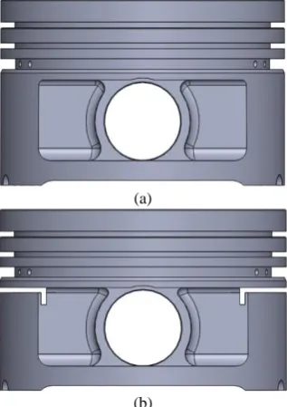
alloy are listed in Table 1. The piston considered as the object of study was taken from the gasoline engine assembled in car Peugeot 405 which is widespread in Iran transport industry. The characteristics of the engine under study are summarized in Table 2. It is made of standardized aluminum alloy in which essential chemical components are as follows: Si (11.5–13%), Cu (0.8–1.5%), Mg (0.8–1.3%), Ni and Fe less than 0.2%, and balance Al [26]. However, in the performed numerical analysis AlSi alloy was taken as the basis material in the simulation. Figure 1 shows the solid model of the piston under study. This model was generated by SolidWorks. A commercial finite element package COSMOS, which has the capability of 3D heat transfer equation, was used for the thermal analysis. As can be seen, great attention was paid for modelling the details of piston geometry. The finite element mesh of the piston model is shown in Figure 1c. 176702 nodes and 860841 tetrahedral elements were used to guarantee the accuracy and acceptability of the results.
The investigations were first performed for traditional and ceramic-coated pistons. In the present study, the ceramic layer was deposited on the top surface of the piston by two different ways: 1) Complete coating of the top surface of the piston. 2) Coating the bowl lip areas on the crown top surface. For each case, the piston was coated with a ceramic layer of MgZrO3
over a bond coat layer of NiCrAl. Original fully and locally coated pistons are given in Figures 2a and 2b.
)a)
(b)
(c)
Figure 1. The model used in FE analysis: a) Image of the traditional piston, b) Piston solid model generated by SolidWorks and c) Finite element model of the piston.
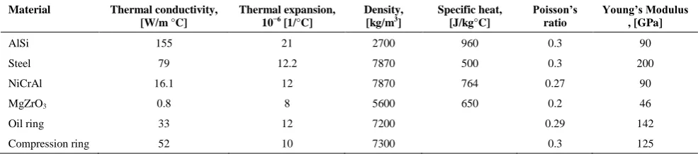
TABLE 1. Material properties of piston, ring and ceramic
Material Thermal conductivity,
[W/m °C]
Thermal expansion,
10−6 [1/°C]
Density,
[kg/m3]
Specific heat, [J/kg°C]
Poisson’s ratio
Young’s Modulus , [GPa]
AlSi 155 21 2700 960 0.3 90
Steel 79 12.2 7870 500 0.3 200
NiCrAl 16.1 12 7870 764 0.27 90
MgZrO3 0.8 8 5600 650 0.2 46
Oil ring 33 12 7200 0.29 142
H. Golbakhshi et al. / IJE TRANSACTIONS A: Basics Vol. 28, No. 10, (October 2015) 1525-1532 1528
3. RESULTS AND DISCUSSIONS
For traditional uncoated piston, the gradient of the temperature was shown in Figure 3. As expected, the high temperatures were observed at the crown region. The maximum temperature was found to be at the lip of crown bowl on the piston top surface. In radial direction, the temperature increases from the crown center towards the bowl lips and the edge of the crown surface. The results show that the temperature on the crown region varies between the two the extreme values of 303 and 250C, while the skirt temperature
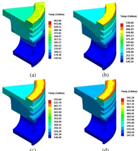
did not exceed 200C.Under the same boundary conditions, the temperature distributions of fully coated piston are shown in Figures 4a to 4d. The thicknesses of ceramic coating layer were 0.2, 0.4, 0.6 and 0.8 mm, respectively. The bond layer had unique thickness of 0.15 mm for all the cases. All the temperature gradients obtained were the same, but the temperatures were different. It was observed that the values of maximum temperature on the coating surface of the crown pistons
were 437.9 , 483.7, 532.8 and 570.1 C, respectively. Because of low thermal conductivity, the temperatures at top surface of coated piston were found to be much higher than those obtained for the traditional piston.
Figure 5 shows the distribution of temperature on top surface of ceramic layer exposed to exploded gases. The maximum temperatures of the piston’s crown top surface were observed for 0.8 mm coating thickness. It was noted that these temperatures were far below the melting point of the ceramic [27].
TABLE 2. Specification of the engine under study
Bore 9.2 cm
Stroke 8.9 cm
Compression ratio 8.7 Connecting rod 13.61 cm Intake Valve Opening (IVO) 34° bTDC
Intake Valve Closing (IVC) 74° aBDC
Electronic Variable Orifice (EVO) 36° bBDC
IP 0.83 bar
IT 297 K
1.1
RPM 3500
Ignition time 55 bTDC
Figure 2. Thermal barrier coating thicknesses over the piston crown: (a) fully coated piston, (b) locally coated piston.
Figure 3. Temperature gradient of traditional piston obtained from thermal analysis
(a) (b)
(c) (d)
Figure 4. The effect of ceramic layer thickness on
temperature distribution for a piston with fully coated top surface; the considered thicknesses are: a) 0.2 mm, b) 0.4 mm, c) 0.6 mm and d) 0.8 mm, respectively.
For a locally coated piston, the bowl lip areas were covered with two bonding and ceramic layers. Four different thicknesses of 0.2 , 0.4 , 0.6 and 0.8 mm were considered for the ceramic layer. Again, the bond layer had unique thickness of 0.15 mm for all cases. The
MgZrO3
NiCrAl
AlSi and Steel
(a)
temperature distributions of locally coated piston are shown in Figures 6a to 6d. It can be observed that moderate temperature gradients exist for pistons with thicker ceramic layers.
For both fully and locally coated pistons, variations in maximum and minimum values of piston temperature gradient with coating thickness are shown in Figures 7 and 8, respectively. It can be seen that the fully and locally ceramic layers have roughly same effects on maximum induced temperature on top surface of the piston. The results show that maximum temperature of the coating surface increases with increased coating thickness.
Figure 5. The effect of coating thickness on temperature distribution of ceramic layer
(a) (b)
(c) (d)
Figure 6. The effect of ceramic layer thickness on
temperature distribution of a locally coated piston; the considered thicknesses are: a) 0.2 mm, b) 0.4 mm, c) 0.6 mm and d) 0.8 mm, respectively.
Figure 7. Variation of maximum temperature of piston top surface with the thickness of fully and locally ceramic layers.
Figure 8. Variation of minimum temperature of piston skirt region with the thickness of fully and locally ceramic layers.
However, the rate of increase in temperature was considerably decreased for thicker coating layers. Using appropriate thickness for fully ceramic coating could cause more decrease in minimum temperature of piston skirt region. For both cases, the fully ceramic coating had better thermal protecting performance for the piston. It was noted that the strength of the material decreases with increasing temperature [28]. So, the service life of the piston would be improved by lowering the temperature of the aluminum substrate surface. The temperature distribution of substrate aluminum surface of piston is plotted in Figures 9 and 10. Different thickness of fully and locally coating layers were considered in the study. For various thicknesses of coating layer, temperature distributions on the piston crown were found to be similar, but with different values. It could be noted that for coated pistons the temperature of aluminum substrate surface were significantly lower than that of the uncoated piston surface, thanks to the low coefficient of thermal conductivity of the ceramic coating. However, compared with the local coating, fully ceramic coating layer on the piston top surface provided more temperature reduction and more positive contribution to the strength of the piston material.
Piston Diameter (mm)
T
e
m
p
e
ra
tu
re
(
oC
)
-40 -20 0 20 40
200 250 300 350 400 450 500 550
0.2 mm thickness 0.4 mm thickness 0.6 mm thickness 0.8 mm thickness
Coating Thickness (mm)
M
a
x
im
u
m
T
e
m
p
e
ra
tu
re
(
oC
)
0.5 1 1.5
440 460 480 500 520 540 560 580 600 620
fully coated piston locally coated piston
Coating Thickness (mm)
M
o
n
o
m
u
m
T
e
m
p
e
ra
tu
re
(
oC
)
0.5 1 1.5
128 130 132 134 136 138 140 142 144 146 148 150 152 154
H. Golbakhshi et al. / IJE TRANSACTIONS A: Basics Vol. 28, No. 10, (October 2015) 1525-1532 1530
Figure 9. Temperature distribution on diameter of piston substrate surface for different thicknesses of fully ceramic coating layer.
Figure 10. Temperature distribution on diameter of piston substrate surface for different thicknesses of locally ceramic coating layer.
(a)
(b)
Figure 11. The front view of the model used in the FE analyses: a) traditional piston, and b) the piston with two horizontal thermal dams
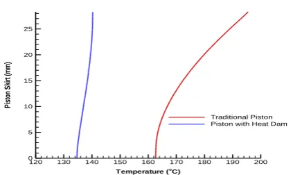
The piston skirt had a direct sliding motion inside the cylinder. So, controlling the temperatures and thermal strains on this region could greatly reduce the friction and related mechanical losses. One of the most common ways for reducing the thermal effects in piston skirt was thermal dam [29]. Schematic view of a traditional aluminum piston with two horizontal gaps is shown in Figure 11b. For both traditional piston and the piston with thermal dam, the temperature gradients are illustrated in Figures 12a and b.
It can be observed that the thermal dam had a considerable effect on reducing the temperature on the skirt region. However, due to less amount of transferred heat, the crown region would have higher temperature compared to the traditional piston.
For better comparison, variation of temperature along the skirt distance is plotted in Figure 13. For both cases, the temperature was lowest at the bottom of the skirt. However, the skirt temperature of a piston with two horizontal heat dams was roughly uniform and much lower than the skirt temperature of the traditional piston.
(a)
(b)
Figure 12. The effect of heat dam on piston temperature gradient: a) for traditional piston b) for piston with two horizontal heat dam
Piston Diameter (mm)
P
is
to
n
S
u
b
st
ra
te
T
e
m
p
e
ra
tu
re
(
oC
)
-40 -20 0 20 40
150 160 170 180 190 200 210 220 230 240 250 260 270 280 290 300
uncoated piston 0.2 mm thickness 0.4 mm thickness 0.6 mm thickness 0.8 mm thickness
Piston Diameter (mm)
P
is
to
n
S
u
b
st
ra
te
T
e
m
p
e
ra
tu
re
(
oC
)
-40 -20 0 20 40
200 210 220 230 240 250 260 270 280 290 300
Figure 13. The effect of heat dam on temperature variation of piston skirt.
4. CONCLUSION
In this work, an elaborated 3D thermal study was conducted for a specified gasoline engine piston. It is found that the crown top surface and the first circular groove had the highest temperatures after calculating the temperature gradient of traditional piston. As an optimization scheme, the top surface of piston crown was coated with ceramic layer. The effect of the thickness of the ceramic layer and fully or locally coating of top crown surface on improving the maximum temperature of the piston were evaluated. It was noted that for fully and locally coated pistons, the temperature of aluminum surface substrate surface were significantly lower than that of uncoated piston. According to the results, thicker coating layers readily provide an increase in temperature on the ceramic top surface and decrease in metal surface temperature. However, fully ceramic coating layer provided 10-15% more thermal protection for the same thickness of ceramic layer. To improve the temperature of piston skirt, two horizontal heat dams were considered for the piston. The results show that the skirt temperature of the piston equipped with heat dam was roughly uniform and much less than that of the traditional piston. By taking these measures, less amount of thermal energy was absorbed by the engine parts which led to higher thermal efficiency and longer service life of the engine. Increased temperature of hot parts was a major cause for shortening the engine service life and waste of energy. By controlling the temperature of the piston, as a main component exposed to the high temperature of exploded gases, higher thermal efficiency and more suitable working conditions could be provided for the internal combustion (IC) engine.
6. REFERENCES
1. Yonushonis, T.M., “Overview of thermal barrier coatings in diesel engines”, Journal of Thermal Spray Technology, Vol. 6, (1997), 50-56.
2. Cerit, M., “Thermo mechanical analysis of a partially ceramic coated piston used in an SI engine”, Surface and coatings
Technology, Vol. 205, (2011), 3499-3505.
3. Buyukkaya, E., “Thermal analysis of functionally graded coating AlSi alloy and steel pistons”, Surface and Coatings
Technology, Vol. 202, (2008), 3856-3865.
4. Buyukkaya, E., Cerit, M., “Thermal analysis of a ceramic coating diesel engine piston using 3-D finite element method”, Surface
and Coatings Technology, Vol. 202, (2007), 398-402.
5. Committee, A.I.H., “ASM Handbook–Volume 1: Properties and Selection: Irons, Steels, and High Performance Alloys”, ASM
International, (1990), 950-980.
6. Esfahanian, V., Javaheri, A., Ghaffarpour, M., “Thermal analysis of an SI engine piston using different combustion boundary condition treatments”, Applied Thermal Engineering, Vol. 26, (2006), 277-287.
7. Liu, X.-B., Pang, M., Zhang, Z.-G., Tan, J.-S., Zhu, G.-X., Wang, M.-D., “Numerical simulation of stress field for laser thermal loading on piston”, Optics & Laser Technology, Vol. 44, (2012), 1636-1640.
8. Luo, Y., Wang, Z., Zeng, J., Lin, J., “Fatigue of piston rod caused by unsteady, unbalanced, unsynchronized blade torques in a Kaplan turbine”, Engineering Failure Analysis, Vol. 17, (2010), 192-199.
9. Yang, Y.-C., Lee, H.-L., “Transient thermal loading induced optical effects in single-coated optical fibers with interlayer thermal resistance”, Optical Fiber Technology, Vol. 14, (2008), 143-148.
10. Goswami, T., “Low cycle fatigue life prediction—a new model”,
International Journal of Fatigue, Vol. 19, (1997), 109-115.
11. Visca, E., Libera, S., Orsini, A., Riccardi, B., Sacchetti, M., “Thermal fatigue equipment to test joints of materials for high heat flux components”, Fusion Engineering and Design, Vol. 49, (2000), 377-382.
12. Cerit, M., Soyhan, H.S., “Thermal analysis of a combustion chamber surrounded by deposits in an HCCI engine”, Applied
Thermal Engineering, Vol. 50, (2013), 81-88.
13. Li, C.-H., Piston thermal deformation and friction considerations, SAE Technical Paper, (1982).
14. Abbes, M.T., Maspeyrot, P., Bouif, A., Frene, J., “A thermomechanical model of a direct injection diesel engine piston”, Proceedings of the Institution of Mechanical
Engineers, Part D: Journal of Automobile Engineering, Vol.
218, (2004), 395-409.
15. Bohac, S.V., Baker, D.M., Assanis, D.N., A global model for steady state and transient SI engine heat transfer studies, SAE
Technical Paper, (1996).
16. Lee, B., Kim, W., “Thermal analysis of a liquid-petroleum-liquid injection engine piston using the inverse heat conduction method”, Proceedings of the Institution of Mechanical
Engineers, Part D: Journal of Automobile Engineering, Vol.
222, (2008), 1033-1045.
17. Lu, X., Li, Q., Zhang, W., Guo, Y., He, T., Zou, D., “Thermal analysis on piston of marine diesel engine”, Applied Thermal
Engineering, Vol. 50, (2013), 168-176.
18. Liu, Y., “Structural and NVH analyses of mixed thin-walled structures using FEA concept models”, International Journal
of Computer Applications in Technology, Vol. 32, (2008),
63-68.
19. Chen, X., Yang, S., Ma, J., He, Z., “The construction of wavelet finite element and its application”, Finite Elements in Analysis
and Design, Vol. 40, (2004), 541-554.
20. Zhao, B., “Thermal stress analysis of ceramic-coated diesel engine pistons based on the wavelet finite-element method”,
Temperature (o
C)
P
is
to
n
S
ki
rt
(m
m
)
120 130 140 150 160 170 180 190 200
0 5 10 15 20 25
H. Golbakhshi et al. / IJE TRANSACTIONS A: Basics Vol. 28, No. 10, (October 2015) 1525-1532 1532
Journal of Engineering Mechanics, Vol. 138, (2011),
143-149.
21. Jalaludin, H.A., Abdullah, S., Ghazali, M.J., Abdullah, B., Abdullah, N.R., “Experimental Study of Ceramic Coated Piston Crown for Compressed Natural Gas Direct Injection Engines”, Procedia Engineering, Vol. 68, (2013), 505-511. 22. Buyukkaya, E., “Effects of thermal barrier coating on a
turbocharged diesel engine exhaust emissions, Sakarya University”, Mechanical Engineering Department, Ph D. thesis, Institute of Sciences and Technology, Turkey, (1997). 23. Nazoktabar, M., Mehdipour, R., Baniamerian, Z., “simulation of
boiling heat transfer within water jacket of 4-cylinder gasoline engine (technical note)”, International Journal of
Engineering-Transactions C: Aspects, Vol. 27, (2014), 19-28.
24. Ostapski, W., “Analysis of thermo-mechanical response in an aircraft piston engine by analytical, FEM, and test-stand investigations”, Journal of Thermal Stresses, Vol. 34, (2011), 285-312.
25. Cerit, M., Coban, M., “Temperature and thermal stress analyses of a ceramic-coated aluminum alloy piston used in a diesel engine”, International Journal of Thermal Sciences, Vol. 77, (2014), 11-18.
26. Ebrahimi, M., Farhadi, M., Sedighi, K., Akbarzade, S., “Experimental investigation of force convection heat transfer in a car radiator filled with SiO 2–water nanofluid”, International
Journal of Engineering Transication B: Application, Vol. 27,
(2014), 333-340.
27. Azadia, M., Rouhaghdam, A.S., Ahangarani, S., “effect of temperature and gas flux on the mechanical behavior of tic coating by pulsed dc plasma enhanced chemical vapor deposition (technical note)”, International Journal of
Engineering-Transactions B: Applications, Vol. 27, (2013),
1243-1250.
28. Golbakhshi, H., Namjoo, M., Mohammadi, M., “A 3D comprehensive finite element based simulation for best Shrink Fit design process”, Mechanics & Industry, Vol. 14, (2013), 23-30.
29. Semin, S., ABU, B.R., Ismail, A., Ali, I., “an experimental investigation of diesel engines fuel injection pressure effect on power performance and fuel consumption”, International
Journal of Engineering-Transactions B: Applications, Vol.
22, (2008), 91-97.
Evaluating the Effects of Ceramic Layer and Thermal Dam on
Optimizing the Temperature Gradient of a Gasoline Engine Piston
TECHNICAL NOTE
H. Golbakhshia, M. Namjoob, E. Raeisi Estabragha
aDepartment of Mechanical Engineering, Faculty of Engineering, University of Jiroft, Iran
bDepartment of Mechanical Engineering of Biosystems, Faculty of Engineering, University of Jiroft, Iran
P A P E R I N F O
Paper history:
Received 25 July 2015
Received in revised form 24 September 2015 Accepted 16 October 2015
Keywords: Piston
Finite Element Method Thermal Analysis Ceramic Layer Thermal Dam
هديكچ
هب و دوبهب روظنم هب هنی زاس ی ارش طی ترارح ی پ درکراک نوتسی کی لخاد قارتحا روتوم ی زنب ینی ، بش هی زاس ی دعب هس ی قد یقی زا ًاتبسن هسدنه پ هدیچی لحت شور کمک هب و هدش ماجنا نآ لی
ددع ی سررب دروم دودحم ءازجا دنمتردق ی
ترارح ی هتفرگ رارق
.تسا ،نیشیپ تاقیقحت فلاخ رب ت رضاح هعلاطم رد
أث ری عون ود ره ارس ششوپ یکیم لک ی ئزج و ی ور ی ناقوف حطس ی پ نوتسی امد رب ی درگ دروآرب نآ جات دی
. ب جیاتن قبط ه هدمآ تسد ، اهنت یلک ششوپ 51
-51 .دومن داجیا یرتشیب یترارح تظافح دصرد