Please cite this article as:M. Delkhosh, M. SaadatFoumani, Multi-Objective Optimization of Hybrid Electric Vehicle Equipped with Power-Split Continuously Variable Transmission, International Journal of Engineering (IJE), TRANSACTIONS C: Aspects Vol. 29, No. 3, (March 2016) 368-377
International Journal of Engineering
J o u r n a l H o m e p a g e : w w w . i j e . i rMulti-objective Optimization of Hybrid Electric Vehicle Equipped with Power-split
Continuously Variable Transmission
M. Delkhosh, M. Saadat Foumani*
Department of Mechanical Engineering, Sharif University of Technology, Tehran, Iran
P A P E R I N F O
Paper history: Received 13October 2014
Received in revised form 01February2016 Accepted 03March2016
Keywords: Hybrid Electric Vehicle Electric Assist Control Strategy Power-split CVT
Optimization Pareto-optimal Fuel Consumption Emission
A B S T R A C T
This paper aims to find the efficient state of hybrid electric vehicle (HEV) by simultaneous optimization of the control strategy and the power train. The power transmission employed in this vehicle is a power-split continuously variable transmission (CVT) which uses several fixed ratio mechanisms. After describing this transmission, the rules of electric assist control strategy are introduced. A modification on this strategy is proposed to decrease the start/stop frequency of the engine and electric motor. Afterwards, an optimization on the HEV’s power train size, power-split CVT and the control strategy is accomplished with the aim of minimizing the vehicle fuel consumption and emissions. The optimization results are some Pareto-optimal points which are tradeoff solutions between fuel consumption and emissions. Finally, in order to intuitively demonstrate the optimality of the optimization results, the Pareto points for the case of considering two objectives are shown.
doi: 10.5829/idosi.ije.2016.29.03c.11
NOMENCLATURE
Higher limit of the battery SOC Launch speed
The battery maximum current Minimum voltage of the EM
Lower limit of the battery SOC Scaling factor of EM
Number of battery modules Scaling factor of ICE
ICE maximum power The importance weight of fi
EM maximum power Greek Symbols
Required power Speed ratio
Minimum voltage of the battery
1. INTRODUCTION1
The vehicles are one of the main energy consumers and air pollutants in the world. Different ways have been examined to reduce their fuel consumption (FC) and tailpipe emissions [1]. One of these ways is to use an electric motor (EM) to assist the internal combustion
11*Corresponding Author’s Email: [email protected] (M. Saadat
Foumani)
engine (ICE) in propelling the vehicle. These vehicles are called hybrid electric vehicle (HEV). EM helps the ICE more constantly operate in the high efficient area and therefore, results lower levels of FC and emissions. Two major types of HEV are series and parallel HEV. Each of these types has some advantages and disadvantages over other type. One of the series type’s advantages is that the ICE is mechanically disconnected from wheels and can operate in high efficient area.
SOC
H VL
max
I VM min
SOC
L SEM
B
N SICE
ICE max
P wi
M max
P
req
P
Figure 1. Structure of multi-FR power-split CVT [2]
In the parallel one, it is not possible due to the direct connection between the ICE and the wheels. A remedy for this shortcoming is to use continuous transmissions instead of discrete transmissions. These transmissions approximately disconnect the ICE from the wheels and permit the ICE to run in the optimal area. These transmissions have increasingly become more common and have been used in several vehicles. Continuously variable transmission (CVT) and power-split CVT are two major types of continuous transmissions. Power-split CVT has some advantages over CVT such as higher power capacity and wider speed ratio range. However, its structure is more complicated and an accurate design is needed to reach highly efficient power-split CVT.
One of the main concerns in the design of hybrid vehicles is the size of its elements. Employing powerful ICE and EM in addition to high capacity energy storage device increases the vehicle weight and also raises its FC and emissions levels. On the other hand, application of smaller ICE and EM along with low capacity energy
storage system degrades the HEV dynamic
performances. Therefore, proper sizing of the HEV elements seems to be necessary.
Another parameter which affects the HEV performance and its FC and emissions levels is the strategy of the power distribution between the ICE and EM. The control strategy of HEV is more complicated than that of non-hybrid vehicle and its design needs more attention. Proper design of control strategy results the ICE operation in the optimal area, prolongs the service life of the energy storage device and also allows the braking energy to be stored in the energy storage device, as much as possible.
As mentioned, HEV’s efficiency can be enhanced by the proper design of the power-split CVT and the control strategy as well as accurate determination of the elements’ sizes. Therefore, these fields have attracted research attention in the last years. Some research have been focused on the optimization of the power train size, while the vehicle transmission is fixed and the control strategy is not changed [3-7]. On the other hand, some studies have been implemented on the
optimization of HEV control strategy while the power train is fixed [8-11]. Furthermore, some research have been conducted on the simultaneous optimization of the HEV control strategy and the power train size [12-17]. Among the studies on these fields, there is no notable research on the simultaneous optimization of the HEV control strategy, the power train size and the power-split CVT transmission. The present study focuses on this field and attempts to find the optimal states of the power train size, power-split CVT and the control strategy. This paper is structured as follows: first, the considered power-split CVT is defined and its simulation model is presented. Afterwards, the rules of the employed control strategy are presented and a method is proposed to prevent frequent engine start/stop during driving. An optimization is implemented on the size of HEV elements, the control strategy parameters and the design variables of the power-split CVT with the aim of
minimizing the vehicle FC and emissions,
simultaneously, and some Pareto-optimal points are achieved. Finally, in order to intuitively demonstrate the optimality of the results attained from the optimization, the Pareto points for the case of considering two objectives (FC and NOX) are obtained and shown.
2. POWER-SPLIT CVT
Power-split CVT is a type of continuous transmissions in which a CVT is connected to a planetary gear (PG) and a fixed ratio (FR) mechanism. In case of proper design, connecting the PG and FR to CVT widens its speed ratio range and also increases its power capacity. However, the speed ratio range of the power-split CVT is limited due to the restricted speed ratio range of CVT and the limitations on the possible speed ratios of PG and FR [18]. A method to increase the speed ratio range of power-split CVT is proposed by Delkhosh and Foumani [2]. In this method, several FRs are embedded in all the possible places and a multi-FR power-split CVT is created. Structure of this transmission is shown in Figure 1. According to this figure, the proposed transmission includes four FRs.
(1)
(2)
In this equation, denotes the elements’ speed ratio and is defined as the output speed divided by input speed.
In summary, the parameters which affect the transmission efficiency are the speed ratios of FRs and PG and the speed ratio range of power-split CVT (
).
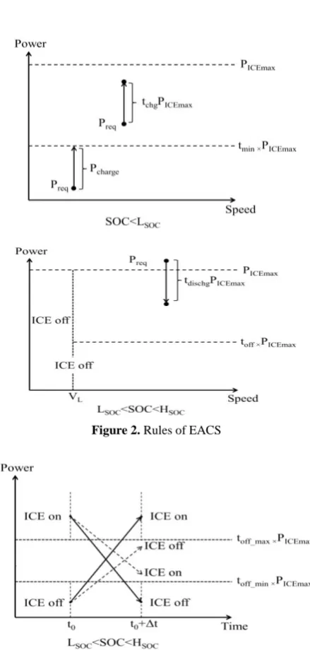
Figure 2. Rules of EACS
Figure 3. Schematic of the method proposed to reduce the start/stop frequency of the ICE and the EM
3. ELECTRIC ASSIST CONTROL STRATEGY
Electric assist control strategy (EACS) is one of the well-known HEV control strategies and belongs to rule-based strategies category. The aim of this strategy is to maintain the energy level of the energy storage device (which is battery in this case) in the recommended range. Furthermore, in this strategy the ICE is the primary power source while the EM assists the ICE in propelling the vehicle. The EM is employed to handle transient variations of required power and the ICE provides an average power. The ICE is not efficient in low powers and low speeds. Therefore, in these cases, the controller employs the EM to propel the vehicle and the ICE is turned off. The rules of EACS are presented as follows:
1- Pure electric or pure thermal mode:
If the vehicle speed is less than launch speed ( ), or if the required power ( ) is smaller than a coefficient ( ) of ICE maximum power ( ), the motor will propel the vehicle. In this case, battery state of charge (SOC) must be more than its lower limit in the recommended range ( ).
If and , the ICE will propel
the vehicle. 2- Hybrid mode:
If and is less than a coefficient ( )
of , the ICE will create a power equal to
, and the extra power ( )
will be used to charge the battery. If , the ICE creates a power equal to and the extra value is used to charge the battery.
If and , the ICE will create
and the rest of is supplied by the EM.
3- Regenerative braking mode:
Through braking, the braking energy is stored in the battery. If the braking power is more than the maximum electric power can be transferred to the battery, mechanical brakes dissipate this power.
The mentioned rules are shown in Figure 2.
One of the problems in this strategy is the frequent start/stop of the ICE and EM (according to the first and second laws). If the required power fluctuates around or the vehicle speed fluctuates around , the ICE and EM are turned on and off, frequently. This behavior is not desirable and a method should be employed to decrease the start/stop frequency of ICE and EM. This method is presented below:
If and the ICE is on, and also the required power in the next moment is lower than
(max) 1 4 (1 ) 2 (max) 3
PS CVT FR FR PG FR CVT PG FR
(min) 1 4 (1 ) 2 (min) 3
PS CVT FR FR PG FR CVT PG FR
(min) (min)
PS CVT PS CVT
L
V
req
P
off
t PICE max
SOC
L
req off ICE max
P t P SOCLSOC
SOC
SOCL
P
req tminICE max
P
min ICE max
t P tminPICE maxPreq
req min ICE max
P t P
req chg ICE max
P t P
req ICE max
P P SOCLSOC
req dischg ICE max
P t P Preq
max
off ICE
t P
V
LSOC
(case 1-1) or the vehicle speed is lower than (case 1-2), the ICE will be turned off in the next moment. On the other hand, if and the
ICE is off, and also (case 2-1) or
(case 2-2), then the ICE will be turned on in
the next moment. In this method, and mean
lower limits of and respectively.
These values are equal to a percent (0.9 in this study) of their corresponding variables. Similarly, and denote upper limits of and , respectively and are equal to a percent (1.1 in this study) of their corresponding variables. Using this method, the start/stop frequency of the ICE and EM will decrease. This method for cases 1-1 and 2-1 is graphically illustrated in Figure 3. The impact of using this method on the start/stop frequency of the ICE and EM will be shown in the following.
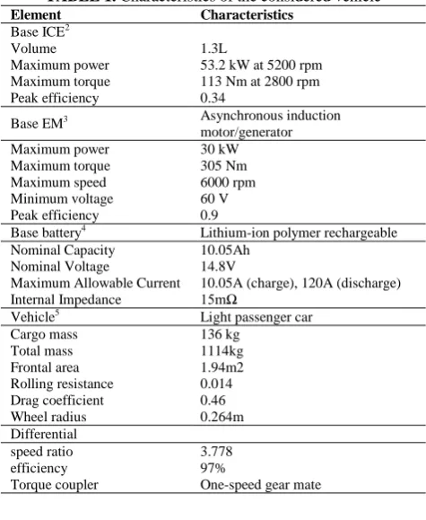
4. VEHICLE CHARACHTERISTICS
In order to optimize the size of HEV elements (ICE, EM, battery), the multi-FR power-split CVT and control strategy, considering a vehicle as the reference is essential. The considered vehicle is a parallel HEV which uses a multi-FR power-split CVT in the pre transmission configuration, as shown in Figure 4.
The vehicle characteristics in addition to the base components (ICE, EM and battery) are shown in Table 1. At each iteration of the optimization process, the performance characteristics of the base components are used to determine the performance characteristics of the components.
ADVISOR is common software for HEV modeling, which uses some simplified models for HEV elements such as ICE, EM, battery, transmission, etc. However, since the present study focuses on the optimization of the HEV equipped with the power-split CVT (which has a complex model), using the ADVISOR may be impossible. Therefore, a model in MATLAB which uses the experimental data of the ICE, EM and battery as well as the simulation model of the presented power-split CVT, are created. The model inputs are the elements’ size, the power-split CVT design parameters and the decision variables of the modified EACS.
Different sub-models of HEV are verified by comparing with experimental data. For example, the model of the power-split CVT is verified through comparison of the efficiency value extracted from it and the experimental data, presented by Mantriota [22]. This comparison is shown in Figure 5.
Figure 4. Configuration of the considered HEV
TABLE 1. Characteristics of the considered vehicle
Characteristics Element
Base ICE2
1.3L Volume
53.2 kW at 5200 rpm Maximum power
113 Nm at 2800 rpm Maximum torque
0.34 Peak efficiency
Asynchronous induction motor/generator Base EM3
30 kW Maximum power
305 Nm Maximum torque
6000 rpm Maximum speed
60 V Minimum voltage
0.9 Peak efficiency
Lithium-ion polymer rechargeable Base battery4
10.05Ah Nominal Capacity
14.8V Nominal Voltage
10.05A (charge), 120A (discharge) Maximum Allowable Current
15mΩ Internal Impedance
Light passenger car Vehicle5
136 kg Cargo mass
1114kg Total mass
1.94m2 Frontal area
0.014 Rolling resistance
0.46 Drag coefficient
0.264m Wheel radius
Differential
3.778 speed ratio
97% efficiency
One-speed gear mate Torque coupler
Figure 5. The comparison of the power-split CVT model and experimental model [22]
2“Mega Motor.” [Online]. Available: http://www.megamotor.ir/.
3“ADVISOR library reorganized structure” [Online]. Available:
http://www.adv-vehicle-sim.sourceforge.net/LibReorg.html/.
4“Gita Battery.”[Online]. Available: http://www.gitabattery.com/.
5“Saipa Corporation.” [Online]. Available:
http://www.saipacorp.com/portal/Home/.
_ min max
off ICE
t P
_ min
L
V
SOC
SOCL
req off _ max ICE max
P t P
_ max
L
VV
_ min
off
t VL_ min
off
t VL
_ max
off
t VL_ max toff VL
0 0.5 1 1.5
0 0.1 0.2 0.3 0.4 0.5 0.6 0.7 0.8 0.9
Speed Ratio
Effi
ci
en
cy
TABLE 2. Variation ranges of optimization parameters
Parameter Range Parameter Range
[2-12] [0.01-0.6]
[0.01-1] [0.01-0.04]
[0.01-0.4] [0.3-0.5]
[0.55-0.85] [0-2]
[1-4] [0.05-20]
, , , [0.25-4] [0.3-1.7]
The figure reveals that there is an acceptable match between the model and the experimental results, and therefore, the model accuracy is satisfactory.
5. OPTIMIZATION OF HEV
As discussed, a proper design for the control strategy and the power train of the HEV is needed to reach an efficient vehicle in terms of dynamic performances, FC and emissions. Therefore, all of the decision variables
of the control strategy ( , , , , , ,
), the design parameters of multi-FR power-split CVT (
, , , , , , ), as
well as the scaling factors of ICE and EM maximum power and the number of the battery modules ( , , ) are considered as the optimization parameters. The variation ranges of these parameters are shown in Table 2. The ranges of and are determined
according to the battery manufacturer
recommendations. The upper limits of and are defined regarding the maximum allowable rate of the battery charge and discharge. The ranges of lower and upper limits of transmission speed ratio are determined regarding the conventional transmissions. The speed ratio ranges of FRs and PG are defined considering the limitations in the production stage. The number of battery modules is determined according to the battery modules to be connected in series and parallel configurations. The required number of battery modules in series is defined by [6]:
(3)
Moreover, the minimum number of battery modules to be connected in parallel can be calculated by [23]:
(4)
As presented in Table 1, the battery maximum current for charge mode is lower than that of discharge mode. Therefore, the maximum allowable current value
in charge mode is assigned to . The Equation (4) is developed according to the fact that the battery should not limit the power which can be transmitted through the EM. During the optimization, different values are assigned to the maximum power of the EM ( ). Therefore, at each iteration of the optimization, the allowable number of battery modules will be determined according to the value, and should be
more than .The ranges of other control
parameters are determined considering the conventional values.
One of the main concerns on the optimization of HEV power train is that if the selected power train satisfies the dynamic performances or not? In order to ensure that the dynamic performances will not decrease during the optimization, some criteria called “Partnership for a New Generation of Vehicles (PNGV)” should be satisfied. These criteria are listed in Table 3. These criteria are considered as the optimization constraints. If the selected set of parameters doesn’t satisfy the optimization constraints, this set will be eliminated and the optimization is run with other set.
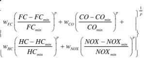
As discussed, the prominent advantage of HEVs over traditional vehicles is their lower FC and emissions. Also, proper selection of control parameters and the design variables of the power train can decrease FC and emissions’ levels as much as possible. Therefore, in this study, the optimization goal is to reduce the vehicle FC and emissions, simultaneously. For this aim, a multi-objective optimization tool is required. There are different methods for multi-objective optimization, e.g. weighted sum, goal attainment, global criterion, etc. The method employed in this paper is the global criterion technique which is one of the well-known methods. In this method, each objective is individually optimized and its extreme value is obtained. Afterwards, the objectives are converted into a single objective function and then this function is minimized. According to this method, the objective function to be minimized can be expressed as:
(5)
where “min” index denotes the minimum of each function found in the first step of the global criterion method. FC is the vehicle fuel consumption in a driving cycle (in L/100km), while CO, HC and NOX are the vehicle emissions (in gr/km). Also, is a constant value (more than 1). Moreover, is the importance weight of each function.
L
V m s toff
min
t tchg
dischg
t LSOC
SOC
H PS CVT (min)
(max)
PS CVT
PG
1
FR
FR2 FR3 FR4 SICE,SEM
L
V toff tmin tchg tdischg LSOC HSOC
(min)
PS CVT
PS CVT (max)
PG
FR1
FR2
FR3
FR4ICE
S SEM B
N
SOC
L HSOC
chg
t tdischg
M min Bseries
B min
V
N round
V
min M max
Bparallel
oc Bseries max
P
N round
V N I
max I
M max P
M max P min Bseries Bparallel
N N
1
p p p
min min
FC CO
min min
p p
min min
HC NOX
min min
F
FC FC CO CO
w w
FC CO
HC HC NOX NOX
w w
HC NOX
p
In order to determine these weights for each objective, the vehicle emissions for some random values of the power train and control strategy parameters are calculated. After averaging, the calculated emissions are compared with European emission standards for light commercial vehicles (1305 kg – 1760 kg)6. These values are listed in Table 4. The fourth column shows the calculated value divided by European standard for each emission.
TABLE 3. PNGV criteria [24]
Performance requirement Value
Gradeability ≥88.5km/h at 6.5% grade in 5
th gear
≥ 30% grade
Acceleration time for
0-97km/h :≤12 sec 0-137km/h: ≤23.4 sec 64-97km/h in 5th gear: ≤5.3 sec
Maximum speed ≥161 km/h
Distance in 5 sec ≥42.7m
TABLE 4. European emission standards and the calculated values for the considered vehicle7
European standard
Calculated value
Calculated value/ European standard (Normalized value)
CO
(gr/km) 1.81 2.74 1.51
HC
(gr/km) 0.13 0.91 7
NOX
(gr/km) 0.1 1.22 12.2
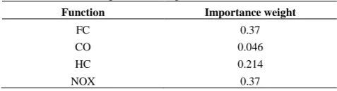
TABLE 5. Importance weights of FC and emissions
Function Importance weight
FC 0.37
CO 0.046
HC 0.214
NOX 0.37
As can be seen, the maximum difference between standard emission and calculated value occurs for NOX. Therefore, it should have the highest importance weight among emissions. Also, the importance weight of FC is considered to be equal to the maximum importance weight. As an example of weight calculation method, the importance weight for CO is calculated as follows:
6“US Environmental Protection Agency.”[Online]. Available:
http://www.epa.gov/.
7“US Environmental Protection Agency.”[Online]. Available:
http://www.epa.gov/.
(6)
The importance weight of other emissions can be calculated similarly. These values in addition to FC importance weight are shown in Table 5.
At each step of the multi-objective optimization process, an optimization tool is needed. In the present study, the Backtracking Search Optimization Algorithm (BSA) is utilized. This method is one of the newest evolutionary algorithms (EA) which has been found to be effective in solving non-differentiable, non-linear and complex optimization problems [25]. BSA is a population-based EA. Its stages are similar to other EA methods: initialization, first section, mutation, cross over and second selection. However, the mutation and crossover stages are different from other EA methods. Since it has only one control parameter, its sensitivity to the control parameter is lower than that of other methods such as PSO, ABC, JDE, etc. Also, including only one control parameter in addition to much simpler structure compared to the other EA methods simplify its application. This method is comprehensively described in [25].
In order to calculate the vehicle FC and emissions, the vehicle motion should be considered in a standard driving cycle. In this study, the SC03 is considered as the studied drive cycle. This cycle has aggressive accelerations and decelerations. Therefore, the hybridization impact can be evaluated accurately. 5.1. Optimization Results Since the ICE optimal area in terms of FC and emissions are approximately distinct, the objectives are in conflict with each other, and there is no optimal solution which results the global minimum of all the objectives. Hence, a set of optimal solutions is achieved instead of one optimal solution. These optimal solutions are called “Pareto-optimal solution”. The definition of Pareto-optimal is as follows: A feasible solution X is a Pareto-optimal, if there is no feasible solution Y such that
for i=1,…,n and the solution Y dominates X for at least one objective [26]. As demonstrated in [26], the Pareto-optimal solutions can be achieved through variation of parameter in Equation (5). The optimal parameters for are listed in Table 6.
The optimal values of the objectives and their reduction percent with respect to the average values presented in Table 5, are shown in Table 7. As can be seen, the most reduction occurs to NOX emission, which has the largest importance weight among all objectives in the defined objective function in Equation (5).
As discussed, the Pareto-optimal solutions can be obtained by assigning different values to parameter in
2
Normlized CO
Normlized Normlized Normlized
CO w
NOX CO HC
i i
f Y f X
p 2
p
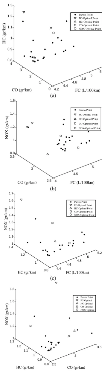
Equation (5). Hence, a set of Pareto points is achieved through changing value of from 2 to 21. These points are shown in Figure 6.
According to this figure, the optimal points in terms of FC and emissions are away from each other. For example, the FC-optimal point has high levels of emissions compared to the Pareto points. The shown Pareto points are tradeoff solutions which increase the designer latitude in designing the PHEV power train and control strategy.
As discussed, a solution was proposed to reduce the start/stop frequency of ICE and EM during the drive cycle. In order to evaluate its impact, the vehicle operation modes through employing the modified strategy (which uses this method) and unmodified one are respectively shown in Figure 7 and Figure 8.
As can be seen, in the unmodified control strategy, the vehicle mode fluctuates between “Engine only mode” and “Hybrid mode”. For example, in 300th second of driving cycle, the operation mode changes from “Engine only mode” to “Hybrid mode”. During this change, the EM is turned on and functions as the EM (discharge mode) or generator (charge mode). After three seconds, the operation mode returns to the “Engine only mode” and the EM is turned off. However, there is no frequent start/stop of the EM and ICE through using the modified control strategy. Consequently, the proposed method decreases the start/stop frequency of EM. As an example, in the considered drive cycle, in case of using the modified strategy, the number of the EM start/stop is 10 times lower than the case of using the unmodified control strategy.
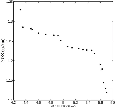
Using the presented method, the Pareto-optimal solutions can be found for each set of objectives. For example, if FC and NOX emissions are considered as the objectives (with equal importance weights) the Pareto-Optimal points will be according to Figure 9. As can be seen, the obtained points create a Pareto-optimal line, and give different choices to the designer in designing the hybrid vehicle.
TABLE 6. The optimal parameters as well as the objective values for p=2
Parameter value Parameter value
11.58 0.03
0.03 0.03
0.10 0.36
0.58 0.43
3.08 0.056
3.83 0.29
1.92 0.57
1.60 0.55
(a)
(b)
(c)
(d)
Figure 6. Pareto optimal solutions and optimal points in terms of FC, CO, HC and NOX
p
L
V m s toff
min
t tchg
dischg
t LSOC
SOC
H PS CVT (min)
(max)
PS CVT
PG
1
FR
FR2
3
FR
FR4
ICE
S SEM
Figure 7. The vehicle operation modes during SC03 for the case of using the modified control strategy
Figure 8. The vehicle operation modes during SC03 for the case of using the unmodified control strategy
Figure 9. Pareto-optimal solutions for the case of considering FC and NOX as the objectives
TABLE 7. The optimal values of the objectives and their reduction percent with respect to the average values
Optimal value Reduction percent (%)
FC (L/100km) 4.35 -
CO (g/km) 2.59 5.47
HC (g/km) 0.85 6.6
NOX (g/km) 1.12 8.2
6. CONCLUSION
The paper is about the simultaneous optimization of the HEV’s control strategy, power train size and its power transmission, while the considered transmission is a multi-FR power-split CVT. This transmission has several design parameters can be changed to reach an efficient transmission. The employed control strategy is EACS. Using this strategy, the ICE and EM are turned on and off frequently. In this paper, a remedy for decreasing the start/stop frequency of the EM and ICE was proposed.
In order to optimize the mentioned parts of HEV, the global criterion method was used. In this method, an importance weight is assigned to each of objectives (which are the vehicle FC and emissions). In order to determine these weights, a method based on decreasing the difference between the vehicle emissions and the European emission standards was used. After optimizing the HEV’s control strategy, power train size and the power transmission, the optimum parameters were obtained. Also, the Pareto-optimal solutions were achieved by changing parameter p in the global criterion method. Reaching these points demonstrates that there are different choices for the designer in determining the decision variables of the studied HEV. Finally, to intuitively demonstrate the optimality of the obtained solutions, the Pareto points for the case of considering two objectives (FC and NOX) were achieved and shown in Figure 9. According to this figure, each point is a Pareto point, which can be a choice for the designer in designing the hybrid vehicle.
7. REFERENCES
1. Pimuzpanuh, V., "Prediction of major pollutants emission in direct-injection dual-fuel diesel and natural-gas engines",
International Journal of Engineering, Vol. 13, No. 2, (2000), 55-68.
2. Delkhosh, M. and Foumani, M.S., "Multi-objective geometrical optimization of full toroidal CVT", International Journal of Automotive Technology, Vol. 14, No. 5, (2013), 707-715. 3. Ehsani, M., Rahman, K.M. and Toliyat, H.A., "Propulsion
system design of electric and hybrid vehicles", Industrial Electronics, IEEE Transactions on, Vol. 44, No. 1, (1997), 19-27.
0 100 200 300 400 500 600 700 800 900
0 10 20 30 40 50 60 70 80 90
Time (sec)
V
eh
icl
e
Sp
eed
(k
m/
h
)
Engine Only Mode Hybrid Mode Regenerative Braking Mode
0 100 200 300 400 500 600 700 800 900
0 10 20 30 40 50 60 70 80 90
Time (sec)
V
eh
icl
e
Sp
eed
(k
m/
h
)
Hybrid Mode Regenerative Braking Mode Engine Only Mode
4.2 4.4 4.6 4.8 5 5.2 5.4 5.6 5.8
1.1 1.15 1.2 1.25 1.3 1.35
FC (L/100km)
N
O
X
(g
r/
k
4. Chu, L., Li, Y. and Wang, Q., ''Study on the parametric optimization for a parallel hybrid electric vehicle power train'',SAE Technical Paper, (2000).
5. Wipke, K., Markel, T. and Nelson, D., "Optimizing energymanagement strategy and degree of hybridization for a hydrogen fuel cell SUV", in Proceedings of 18th Electric Vehicle Symposium., (2001).
6. Galdi, V., Ippolito, L., Piccolo, A. and Vaccaro, A., "A genetic-based methodology for hybrid electric vehicles sizing", Soft Computing, Vol. 5, No. 6, (2001), 451-457.
7. Roy, H.K., McGordon, A. and Jennings, P.A., "A generalized powertrain design optimization methodology to reduce fuel economy variability in hybrid electric vehicles", Vehicular Technology, IEEE Transactions on, Vol. 63, No. 3, (2014), 1055-1070.
8. Won, J.S., Langari, R. and Ehsani, M., "An energy management and charge sustaining strategy for a parallel hybrid vehicle with CVT", Control Systems Technology, IEEE Transactions on , Vol. 13, No. 2, (2005), 313-320.
9. Kheir, N.A., Salman, M.A. and Schouten, N.J., "Emissions and fuel economy trade-off for hybrid vehicles using fuzzy logic",
Mathematics and Computers in Simulation, Vol. 66, No. 2, (2004), 155-172.
10. Wang, Z., Huang, B., Xu, Y. and Li, W., "Optimization of series hybrid electric vehicle operational parameters by simulated annealing algorithm", in Control and Automation, ICCA, IEEE International Conference on, (2007), 1536-1541.
11. Wu, J., Zhang, C.H. and Cui, N.X., "PSO algorithm-based parameter optimization for HEV powertrain and its control strategy", International Journal of Automotive Technology, Vol. 9, No. 1, (2008), 53-59.
12. Montazeri-Gh, M. and Poursamad, A., "Application of genetic algorithm for simultaneous optimisation of HEV component sizing and control strategy", International Journal of Alternative Propulsion, Vol. 1, No. 1, (2006), 63-78.
13. Long, V. and Nhan, N., "Bees-algorithm-based optimization of component size and control strategy parameters for parallel hybrid electric vehicles", International Journal of Automotive Technology, Vol. 13, No. 7, (2012), 1177-1183.
14. Assanis, D., Delagrammatikas, G., Fellini, R., Filipi, Z., Liedtke, J., Michelena, N ,.Papalambros, P., Reyes, D., Rosenbaum, D. and Sales, A., "Optimization approach to hybrid electric propulsion system design∗", Journal of Structural Mechanics, Vol. 27, No. 4, (1999), 393-421.
15. Fang, L.C. and Qin, S.Y., "Concurrent optimization forparameters of powertrain and control system of hybrid electric vehicle based on multi-objective genetic algorithms", in SICE-ICASE, International Joint Conference, IEEE, (2006), 2424-2429.
16. Wu, L., Wang, Y., Yuan, X. and Chen, Z" ,.Multiobjective optimization of HEV fuel economy and emissions using the self-adaptive differential evolution algorithm", Vehicular Technology, IEEE Transactions on, Vol. 60, No. 6, (2011), 2458-2470.
17. Delkhosh, M., Foumani, M.S. and Boroushaki, M. ,. "Geometrical optimization of parallel infinitely variable transmission to decrease vehicle fuel consumption", Mechanics Based Design of Structures and Machines, Vol. 42, No. 4, (2014), 483-501.
18. Delkhosh M. and Saadat Foumani M., "Introduction and optimization of a power split continuously variable transmission including several fixed ratio mechanisms", Scientia Iranica, Vol. 22, (2015), 226-234.
19. Delkhosh, M., SaadatFoumani, M. and Rostami, P., "Application of multi-objective optimization for optimization of half-toroidal continuously variable transmission", International Journal of Engineering, Vol. 27, No. 9, (2014), 1449-1456. 20. Delkhosh, M. and Foumani, M.S., "Modelling and optimization
of toroidal continuously variable transmission in ECE driving cycle", InternationalJournal of Engineering, Vol. 26, No. 12, (2013), 1535-1542.
21. Mantriota G., "Performances of a series infinitely variable transmission with type I power flow", Mechanism and Machine Taheory, Vol. 37, (2002), 579-597.
22. Montazeri-Gh, M., Poursamad, A. and Ghalichi, B., "Application of genetic algorithm for optimization of control strategy in parallel hybrid electric vehicles", Journal of the Franklin Institute, Vol. 343, No. 4, (2006), 420-435.
23. Delkhosh, M., SaadatFoumani, M. and Rostami, P ,. "Optimization of power train and control strategy of hybrid electric vehicles", Scientia Iranica. Transaction B, Mechanical Engineering, Vol. 22, No. 5, (2015), 1842-1854.
24. Schouten, N.J., Salman, M.A. and Kheir, N.A., "Energy management strategies forparallel hybrid vehicles using fuzzy logic", Control Engineering Practice, Vol. 11, No. 2, (2003), 171-177.
25. Civicioglu, P., "Backtracking search optimization algorithm for numerical optimization problems", Applied Mathematics and Computation, Vol. 2 ,No. 15, (2013), 8121-8144.
Multi-objective Optimization of Hybrid Electric Vehicle Equipped with Power-split
Continuously Variable Transmission
M. Delkhosh, M. Saadat Foumani
Department of Mechanical Engineering, Sharif University of Technology, Tehran, Iran
P A P E R I N F O
Paper history: Received 13 October 2014
Received in revised form 01February 2016 Accepted 03March 2016
Keywords: Hybrid Electric Vehicle Electric Assist Control Strategy Power-split CVT
Optimization Pareto-optimal Fuel Consumption Emission
هديكچ
هنیهب کمک هب یکیرتکلا دیربیه یوردوخ هنیهب تلاح نتفای فده ،هلاقم نیا رد زیاس ،یلرتنک یژتارتسا نامزمه یزاس
ناملا تسا دودحمان لیدبت تبسن عون زا وردوخ نیا رد هدافتسادروم تردق لاقتنا متسیس .تسا تردق لاقتنا متسیس و اه
لماش هک یژتارتسا نیناوق ،تردق لاقتنا متسیس نیا یفرعم زا سپ .تسا تباث لیدبت تبسن مزیناکم نیدنچ
EACS
هئارا
یم یلرتنک یژتارتسا یور حلاصا کی ،یکیرتکلا و یقارتحا روتوم ندش شوماخ و نشور سناکرف شهاک یارب .دوش
EACS
یم داهنشیپ هنیهب کی سپس .دوش ،تردق لاقتنا متسیس یور یزاس
ناملا زیاس شهاک فده اب یلرتنک یژتارتسا و اه
یم ماجنا یگدنیلاآ و تخوس فرصم نامزمه هنیهب هجیتن .دوش
هطقن یدادعت یزاس
Pareto
نیب لداعت کی هک تسا
یم رارقرب یگدنیلاآ و تخوس فرصم هنیهب جیاتن ندوب هنیهب یدوهش تابثا یارب ،تیاهن رد .دنک
طاقن ،یزاس
Pareto
یارب
نآ رادومن و هدمآ تسدب فده عباوت ناونع هب عبات ود نتفرگ رظن رد تلاح یم مسر اه
.دوش
![Figure 1. Structure of multi-FR power-split CVT [2]](https://thumb-us.123doks.com/thumbv2/123dok_us/219481.2016453/2.595.56.282.97.220/figure-structure-multi-fr-power-split-cvt.webp)