RESEARCH NOTE
FINITE ELEMENT PREDICTION OF THE BEHAVIOR OF
PROFILED STEEL SHEET DRY BOARD FOLDED PLATE
STRUCTURES – AN IMPROVED MODEL
Ehsan Ahmed
Department of Civil Engineering, BIT Chittagong, Bangladesh, [email protected]
Wan Hamidon Wan Badaruzzaman
Department of Civil and Structural Engineering, UKM Malaysia, [email protected]
(Received: March 12, 2002 –Accepted: December 20, 2002)
Abstract This paper describes an alternative finite element model that would yield more accurate results in the prediction of the behavior of Profiled Steel Sheet Dry Board (PSSDB) folded plate structures, which can be considered as an improvement of an earlier proposed model. The PSSDB folded plate structures are being proposed as an alternative to traditional forms of roof construction. The PSSDB system is an innovative composite structural system initially envisaged by Wright and Evans. It consists of profiled steel sheeting connected to dry board by simple drilling and self-tapping screws. The folded plate roof model under study incorporates individual PSSDB panel assembled and connected to each other by ridge connection plates. Full-scale model of 6-meter span was tested in the laboratory to confirm theoretical models proposed by the authors. The earlier reported model was based on an orthotropic idealization of the profiled steel sheet, and two directional ‘dummy’ plate element in modeling the connection between profiled steel sheet and dry board; a model that has been concluded to be giving good and reasonably accurate results. However, the accuracy of the predicted results could be improved by modeling the profiled steel sheet as an isotropic plate element, and utilizing ‘joint’ element instead of the ‘dummy’ plate element to model the connections involved in the PSDDB folded plate structures. This is the focus of this paper. Results found from the newly proposed model generally over-estimated the experimental results, and are within 34% of the experimental model.
Key Words Profiled Steel Sheeting, Dry Boards, Finite Element, Improved Model, Experiment
!"#$%
&&&&&&&&&&&&&&&&&'()*+&,-.-+&/01&23&4#5)(6&7&)893):;6&'<#=(&>,-&!;)1&.)=?.&'5)0:&@3-&&& A
&&&&&&&)B&,.)$=C-&'DEF&)C&'G&H=:&
&&&&&&&&&I#?7HJ&+KL?&M.7&29N&+HC&;-&!"O
(PSSDB)
&&&&&&P:&QHO&-.&!"O&'=N)1& &
"*+ &R &&&&&&&HC&IS=9:&!"O&)B&M.7&/01
&$=C-&PT$O &&&&,)8T()J&;-&,.)
PSSDB
&&&&'G&U1-& &&&&&&&&&&&&&&.+&7&HV3"$3&'C&2B&2B&/01&W7-"=:&,)*&!"XXG&IY=:&Z1LB
'OL[ & !"O&IY=:&.-+&'37-;&\)DEF&'C&)* &
"(-&R &/01&'(LVX3-&I#TDB&,-HC&P5":&>+7"D:&])S5-&^7.&;-&!+)E=1-&)C
&&&&&&&&&&&&&&&&&_[.)C&7&,"`&Z3-HO&UDB&PCH<B&,)8=aB&b)<(-&c3Hd&;-&]6&.)e=f-&7&!"O&+)8X9#J&P(;
&&&!"#<X1&/T=g:&,.-U1-&!"O &R &P3)(-LB&>)893):;6&'<#=(
PSSDB
P:&\)eh-&'C&/01&@=N)1&W7-"=:&,)8O7.&PX34V3)i&.+&-.& &
"()1. R
1. INTRODUCTION
This paper deals with an alternative finite element modeling technique of a type of folded plate roof construction based on an innovative Profiled Steel
complicated problems including the PSSDB composite roofing system reported in this paper.
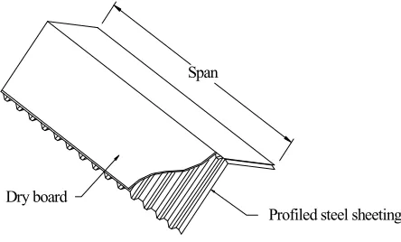
The PSSDB system is a composite structural system firstly envisaged by Wright and Evans [2,3]. The system is gaining popularity in its application as flooring, walling, and roofing units in building [4]. Folded plate roof which is the focus of this paper is surface structure constructed from individual plane surfaces, or plates, joined together to form a composite surface. Such type of construction has been extensively used in the construction of long span roof systems because of the economy and interesting architectural appearance. The PSSDB composite system consists of profiled steel sheet connected to dry boards by means of mechanical connectors (drilling and self-tapping screws) is a structural load bearing system. Panels formed from the proposed PSSDB system can be assembled to form folded plate structures (see Figure 1). In this situation, the system carries both the in plane and out-of plane bending and shear. Such a combination will result in a strong and efficient structure with many advantages over traditional forms of construction [5-8].
The earlier reported finite element model [1] was based on an orthotropic idealization of the profiled steel sheet (considered to be the main
structural component), and two directional ‘dummy’ plate element in modeling the connection between profiled steel sheet and dry board, a model which has been concluded to be giving good and reasonably accurate results. However, the authors in a more recent development found that the accuracy of the predicted results could be improved further by modeling the profiled steel sheet as an isotropic plate element, and utilizing ‘joint’ element instead of the ‘dummy’ plate element to model the connections involved in the PSDDB folded plate structures.
2. THE EXPERIMENTAL MODEL
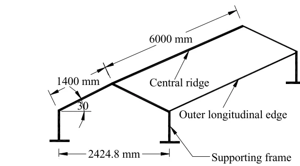
The experimental model used to verify the newly proposed modeling technique is exactly the same as the one that has been reported earlier [1]. It is a one bay folded plate roof structure as shown in Figure 1. The span of the model is 6 meter. It is supported on two end supporting frames. The overall width of the model is 2.43 meter. The cross-sectional dimension of the structure is illustrated in Figure 2(a), and the overall dimensions are given in Figure 2(b).
The model was built in two stages. Tests were conducted after the completion of each stage. In the first stage, bare proprietary profiled steel sheeting, Trimdek [9], 0.42 mm thick was used to construct the model, referred to as Model A. In the second stage, an enhancement of Model A was made by attaching a layer of 12-mm thick Cemboard [10] (a proprietary type of cement board) on top of the steel sheeting by means of self drilling, self tapping screws. This finally formed the PSSDB folded plate model referred to as Model B. Steel angle plate was used to function as the central ridge connecting the two side PSSDB panels to ensure a rigid connection between them. At the outer ridges, steel angle plates were introduced to stiffen these otherwise very flexible outer edges (refer to Figure 3). A view of the completed model in the laboratory is shown in Figure 4.
Dry board
Profiled steel sheeting Span
3. TEST CASES
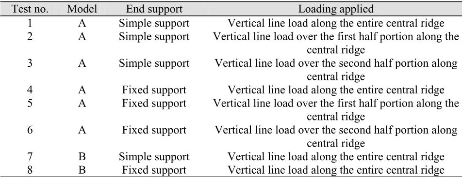
Table 1 lists the experimental test cases detailing out the end support and loading conditions. Figure 5 gives the illustrations of the loading conditions. The variations in the end support conditions were achieved by varying the connection details (by adjusting the bolt and nut arrangements) in between the ridge plates and the two end frames. However, the profiled steel sheeting panels, which were supported, only on the ridge plates can be considered to be unrestrained by the end frames. The simple support condition allowed free movements (translational and rotational) in the longitudinal direction perpendicular to the frames,
whilst all movements (translational and rotational) in the vertical and transverse directions were restrained. On the other hand, the fixed support condition ensured that all degrees of freedom in all directions were completely restrained. Load Cases 2 and 3 (see Figure 5) applied onto Model A were used to ensure the reliability of the experimental results in terms of their observance of the principle of superposition.
4. INSTRUMENTATION
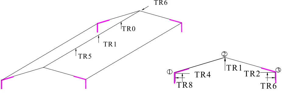
Figure 6 shows the positions of the displacement transducers installed underneath the model during
30 30
30 1400 mm
6000 mm
Supporting frame 1400 mm
2424.8 mm
Outer longitudinal edge Central ridge
Figure 2. (a) Cross-section of the model, (b) Overall view of the model.
Steel angle plate
Profiled steel sheeting
Self drill-self tap screws (150 X 150 X 6mm)
Details of Ridge Connection
Details of Edge Connection
50 50 50
Self drill-self tap Screw
Steel Angle Plate
Profiled steel sheeting
3@50mm=150mm
the experimental tests. They were provided to record the vertical, lateral and longitudinal displacements
of the ridges at selected positions. The transducers were graduated in units of 0.01 mm. The readings Figure 4. View of completed model in the laboratory.
TABLE 1. Experimental Test Cases.
Test no.
Model
End support
Loading applied
1
A
Simple support
Vertical line load along the entire central ridge
2
A
Simple support
Vertical line load over the first half portion along the
central ridge
3
A
Simple support
Vertical line load over the second half portion along
central ridge
4
A
Fixed support
Vertical line load along the entire central ridge
5
A
Fixed support
Vertical line load over the first half portion along the
central ridge
6
A
Fixed support
Vertical line load over the second half portion along
central ridge
7
B
Simple support
Vertical line load along the entire central ridge
made by the transducers were recorded directly by an electronic portable data logger. In addition, end displacement in the longitudinal direction of the end frame near the central ridge was also recorded. This would allow for the behavior of these end supports to be studied. Sufficient experimental data in order to assess the accuracy of the analytical solution were obtained by these deflection measurements. Also, a comprehensive picture of
the cross-sectional behavior under loading can be obtained.
5. TESTING PROCEDURE
The tests conducted on the model followed the same procedure each time. It is very important to first calibrate all the transducers and load cell prior
Unsymmetrical Loading in Case 2 Unsymmetrical Loading in Case 3
Symmetrical Loading in Case1
Figure 5. Loading considered on model structures.
1
2
3
TR1
TR4
TR8
TR2
TR6
TR1 TR0
TR5
TR6
(
a) Position of Transducer along the Central Span (b) Position of Transducers at Mid-Spanto the tests. The transducers were first initialized in the unloaded stage. Load was applied in 10 to 12 increments on the model, and steps were taken to ensure that the elastic range was not exceeded. The model was found to have returned to the initial positions after unloading indicating that the elastic range has not been exceeded.
6. FINITE ELEMENT SOLUTION
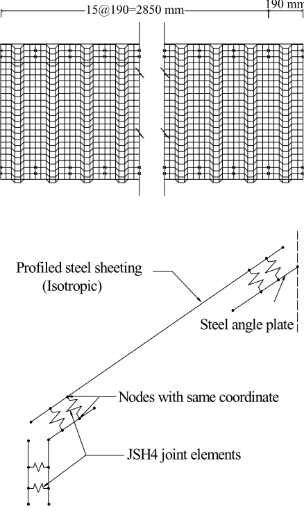
As mentioned earlier, a theoretical prediction based on the finite element method has been proposed [1]. The earlier model proposed the profiled steel sheeting to be modelled as an equivalent homogeneous orthotropic thin shell plate elements of constant thickness, whilst two directional ‘dummy’ plate elements were proposed in modeling the connection between profiled steel sheeting and dry board. In this paper, an alternative finite element model is proposed in an effort to improve the accuracy of the predicted results, where in this case, the profiled steel sheeting is modeled as an isotropic plate element, whilst ‘joint’ elements instead of the ‘dummy’ plate elements are employed in modeling all the connections involved in the PSSDB folded plate structure. Lusas [11] finite element software was employed in the modeling.
7. FINITE ELEMENT MODELLING DETAIL
A full description of the PSSDB folded plate model has been described earlier. Figures 8 and 9
illustrate the finite element models of Models A and B respectively. In the modeling, the 0.42 mm
760 mm Coverage
190
130
26
60
29
Figure 7. Cross-section of Trimdek profiled steel sheeting.
190 mm 15@190=2850 mm
JSH4 joint elements Profiled steel sheeting
Steel angle plate (Isotropic)
Nodes with same coordinate
thick Trimdek Hi-Ten [9] (see Figure 7) profiled steel sheeting was considered as an assembly of isotropic plates, with a Young’s Modulus value of 210x103 N/mm2 (obtained from the manufacturer). The 6 mm thick steel angle plates (see Figure 3) used for the connection at the central ridge and for stiffening the longitudinal edges, and also the layer of 12 mm thick Cemboard were modeled as isotropic plates, with Young’s Modulus values of 210x103 N/mm2 (assumed value) and 5250 N/mm2 (test value) respectively. ‘Joint’ elements were proposed to model, (i) the connections between Cemboard and profiled steel sheeting, and to model, (ii) the connections between steel angle plates and profiled steel sheeting, with connection stiffness values of K1 = 625 N/mm2 (test value) and K2=210×103N/mm2 (predicted value) respectively. QSI4 thin shell element [11] was chosen to model all the plate elements, as this is more affordable in terms of computer memory, space and time. Compatible joint element JSH4 [11] was chosen to model the connections. Only one quarter of the roofing was modeled for symmetrical loading situation, whereas half model was considered in the case of unsymmetrical loading. The resulted symmetric situations in both the cases were modeled by giving boundary nodes appropriate boundary conditions. Line load per unit length was assigned along the central ridge on the angle plate to simulate different experimental loading conditions.
8. RESULTS
This section reports on the results obtained from the newly proposed finite element model and those obtained from the previously proposed finite element [1] and experimental models. The discussions are confined to the ridge deflection values at the mid-span section for transducers positions previously shown in Figure 6(b). Average values of readings from symmetrically positioned transducers were computed for comparison purposes. A load intensity of 0.6 N/mm applied along the central ridge of the model was considered in all cases to compare results with values obtained experimentally. Comparison of deflection values at mid-span of the central and edge ridges for full length line loading obtained from theoretical predictions and experimental model for all tests can be seen in Tables 2 to 7. In general, both the proposed finite element models were able to predict the general trend of displaced shapes of both experimental Models A and B (see reference [1] and Figures 10 to 13). This is the first step towards the verification of the finite element models. Secondly, both the finite element models have managed to identify positions of smallest and highest values of deflections correctly, and also in the correct ratios. Thirdly, Model B that was expected to be more rigid than Model A by virtue of the addition of the Cemboard layer was found to be more rigid experimentally and theoretically. This is an indication of the reliability of the finite element models.
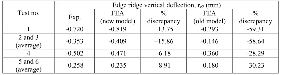
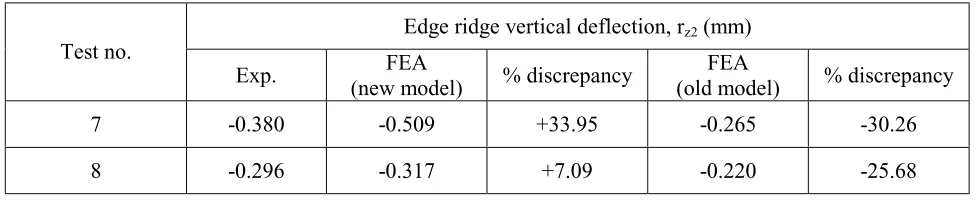
Except for one or two odd cases, the newly proposed finite element model was seen to be producing more accurate results with much less discrepancies. Furthermore, there appeared to be a general trend of results obtained from this model to be overestimating the experimental deflection values. This is good and can be considered safe as far as design of the structure is concerned. The previous finite element model [1] would always underestimate the deflection values of the folded plate structure. The highest negative discrepancy values (underestimated values) obtained were 31.5% (see Table 2) and 59.3% (see Table 4) from the newly proposed finite element, and the previously proposed finite element models respectively. On the other hand, the highest positive discrepancy value obtained from the
Dry Boarding
(Isotropic)
Steel angle plates
Profiled Steel Sheeting Joint elements Nodes with very slight gap
Scale = 1/ 8.5
Deflection x 40
Undeformed
Experimental
FEA
Figure 10. Mid-span deflected ridge position of Test 1 (model a simple support).
Undeformed
Experimental
FEA
Scale = 1/ 8.5
Deflection x 40
Figure 11. Mid-span deflected ridge position of Test 4 (model a fixed support).
Scale = 1/8.5
Deflection x 40
Undeformed
Experimental
FEA
Scale = 1/8.5
Deflection x 40
Undeformed
Experimental
FEA
Figure 13. Mid-span deflected ridge position of Test 8 (model b fixed support).
TABLE 2. Mid-Span Central Ridge Vertical Deflection for Model A in all Tests (Tests 1 to 6).
Central ridge vertical deflection, rz2 (mm) Test no.
Exp. FEA
(new model) % discrepancy
FEA
(old model) % discrepancy
1 +2.554 +2.460 -3.68 +2.353 -7.87
2 and 3 (average) +1.229 +1.230 +0.08 +1.176 -4.31
4 +1.948 +1.504 -22.79 +1.450 -25.56
5 and 6 (average) +1.098 +0.752 -31.51 +0.725 -33.97
TABLE 3. Mid-Span Edge Ridge Lateral Deflection for Model A in all Tests (Tests 1 to 6).
Edge ridge lateral deflection, rz1 (mm) Test no.
Exp. FEA
(new model) % discrepancy
FEA
(old model) % discrepancy
1 +1.869 +1.887 +0.96 +1.457 -22.04
2 and 3 (average) +0.941 +0.943 +0.21 +0.728 -22.64
4 +1.218 +1.165 -4.35 +1.012 -16.91
5 and 6 (average) +0.765 +0.582 -23.92 +0.507 -33.73
TABLE 4. Mid-Span Edge Ridge Vertical Deflection for Model A in all Tests (Tests 1 to 6).
Edge ridge vertical deflection, rz2 (mm) Test no.
Exp. FEA
(new model)
% discrepancy
FEA (old model)
% discrepancy
1 -0.720 -0.819 +13.75 -0.293 -59.31
2 and 3
(average) -0.353 -0.409 +15.86 -0.146 -58.64
4 -0.502 -0.471 -6.18 -0.360 -28.29
5 and 6
newly proposed model was about 34% (see Table 7). This led to the conclusion that the proposed method of modeling described in this paper is more reliable compared to the previously proposed model [1]. The most accurate result with almost zero discrepancy obtained from this finite element was 0.08% (see Table 2).
9. COMMENTS
Reasons for the some discrepancies in results (even though some are having positive effect) have been described earlier [1]. Generally, it was observed that the big difference between theoretical and experimental results occurred at the outer ridge for
the vertical deflection, rz1. This deflection is the smallest amongst all the measured deflections, and very small relative to the largest deflections that occur vertically at the central ridge (rz2). Therefore, it would be very difficult to achieve a reliable comparison for such a small value of deflection, and hence the error observed may be attributed to the fact that these values were indeed very small. T he variation between theoretical and experimental results may also be attributed to the assumptions and simplification made in the finite element modeling which may not have simulated exactly the real conditions. The effect of attaching Cemboard, and the effect of varying the end support conditions have also been described in detail earlier [1] and would not be dealt with here. The intention of this paper is to show that the TABLE 5. Mid-Span Central Ridge Vertical Deflection for Model B in all Tests (Tests 7 and 8).
Central ridge vertical deflection, rz2 (mm) Test no.
Exp. FEA
(new model) % discrepancy
FEA
(old model) % discrepancy
7 +1.540 +1.520 -1.30 +1.388 -9.87
8 +1.271 +1.030 -18.96 +1.080 -15.03
TABLE 6. Mid-Span Edge Ridge Lateral Deflection for Model B in all Tests (Tests 7 and 8).
Edge ridge lateral deflection, rz1 (mm) Test no.
Exp. FEA
(new model) % discrepancy
FEA
(old model) % discrepancy
7 +1.142 +1.164 +1.93 +0.808 -29.25
8 +0.692 +0.770 +11.27 +0.588 -15.03
TABLE 7. Mid-Span Edge Ridge Vertical Deflection for Model B in all Tests (Tests 7 and 8).
Edge ridge vertical deflection, rz2 (mm) Test no.
Exp. FEA
(new model) % discrepancy
FEA
(old model) % discrepancy
7 -0.380 -0.509 +33.95 -0.265 -30.26
newly proposed finite element modeling technique is much better than the previously proposed model. The isotropic modeling of profiled steel sheet seemed to be producing more accurate results compared to the orthotropic plate modeling. A reason that could be attributed to this would be that the idealization of profiled steel sheet as an equivalent homogeneous orthotropic thin shell plate elements of constant thickness is quite difficult to match the real situation due to the ‘estimated’ analytical assumptions made for the equivalent plate properties for both the in-plane and out-of-plane behavior.
10. CONCLUSIONS
This paper has described an improved and more reliable finite element model compared to the one that was reported previously [1] that would yield more accurate results in the prediction of the behavior of PSSDB folded plate structures. The proposed model is based on an isotropic plate modeling of profiled steel sheeting, steel angle connecting and stiffening plates at the ridges, with the joints between profiled steel sheeting to Cemboard and the joint between profiled steel sheeting to the angle plate modeled as ‘joint’ elements. From the investigations, the following conclusions can be drawn:
• Even though the construction of the experimental model especially at the ridges was quite complex, and the model was of quite a large scale, the theoretical results still show very reasonable and acceptable degree of accuracy.
• The variation between the theoretical and experimental results is acceptable and consequently, the proposed finite element models can be used safely for the practical design of such structures.
• The proposed isotropic and ‘joint’ model (new model) yielded more accurate results compared to the orthotropic and ‘dummy’ plate model (old model), and hence is more recommended for the analysis of PSSDB folded plate structures.
• The biggest discrepancies that were found in both the new and old finite element models
were 33.95% and 59.31% respectively. They were however observed for very small values (almost zero) of ridge deflections and hence should have been expected. The reduction in percentage discrepancy by the new model clearly confirms the earlier above conclusions. • The new model generally slightly
over-estimates the real deflections of the PSSDB folded plate model.
• The folded plate roof model tested shows satisfactory structural behavior and has the potential to be used in practice.
11. ACKNOWLEDGEMENTS
The Ministry of Science, Technology and the Environment, Malaysia and Universiti Kebangsaan Malaysia have funded the research works reported in this paper. Various testing materials have been supplied free of cost by BHP Steel Building Products Malaysia and Hume Cemboard Malaysia. The authors would like to express sincere gratitude for all the supports provided.
12. REFERENCES
1. Ahmed, E., Wan Badaruzzaman, W. H. and Wright, H. D., “Experimental and Finite Element Study of Profiled Steel Sheet Dry Board Folded Plate Structures”, Thin-Walled Structures 2000, Vol. 38, No. 2,125-143. 2. Wright, H. D. and Evans, H. R., “Profiled Steel Sheeting
for the Replacement of Timber Flooring in Building Renovation”, SERC Grant GR/D/76875, (1986). 3. Wright, H. D., Evans, H. R. and Burt, C. A., “Profiled
Steel Sheet/Dryboarding Composite Floors”, The Structural Engineer 1989, Vol. 67, No. 7/4, 114-129. 4. Wan Badaruzzaman, W. H., Akhand, A. M., Shodiq, H.
M., Khalim, A. R. and Taib, K. A., “Development and Applications of Composite Profiled Steel Sheet Dry Board Floor System”, Proceedings of the Conference on Construction Technology, University Malaysia Sabah, (2001), 29-38.
5. Wan Badaruzzaman, W. H., “The Behavior of Profiled Steel Sheet/Dryboard System”, PhD Thesis, School of Engineering, University of Wales, Cardiff, (1994). 6. Ahmed, E., “Behavior of Profiled Steel Sheet Dry Board
Folded Plate Structures”, PhD Thesis, Faculty of Engineering, University Kebangsaan, Malaysia, (1999). 7. Wan Badaruzzaman, W. H. and Wright, H. D.,
Proceedings of the Second International Conference o n T h i n - W a l l e d S t r u c t u r e s, R e s e a r c h and Development, National University of Singapore, (1998), 355-365.
8. Ahmed, E., Wan Badaruzzaman, W. H. and Wright, H. D., “Finite Element Elastic Analysis of Profiled Steel Sheet Dry Board Composite Panels”, Proceedings of the Sixth ASCCS International Conference, Los Angeles, (2000), 1083-1090.
9. BHP Steel Building Products, "Trimdeck Profiled Decking", BHP Steel Building Products Catalogue, Malaysia, (1995).
10. Hume Cemboard Berhad, "Cemboard Cement Board", Hume Cemboard Berhad Catalogue, Malaysia, (1996).