Volume 2, Issue 8, August 2013
Page 162
Abstract
In this paper Direct flux vector control based on space vector modulation (DFVC-SVM) preserve DFVC transient merits, furthermore, produce better quality steady-state performance in a wide speed range. At each cycle period, SVM technique is used to obtain the reference voltage space vector to exactly compensate the flux and torque errors. The t orque ripple of DFVC-SVM in low speed can be significantly improved. This scheme DFVC-SVM can used where field weakening operation (FOC) is required. In this paper, SVM-DFVC technique based on input-output linearization control scheme for induction machine drives is developed. Furthermore, a robust full-order speed adaptive stator flux observer is designed for a speed sensor less DFVC-SVM system and a speed-adaptive law is given. The observer gain matrix, which is obtained by solving linear matrix inequality, can improve the robustness of the adaptive observer gain. The stability of the speed adaptive stator flux observer is also guaranteed by the gain matrix in very low speed. The proposed control algorithms are verified by extensive simulat ion results. The results are verified by the MATLAB/SIMULINK.
1. Introduction:
An induction motor (IM) is a type of asynchronous AC motor where power is supplied to the rotating device by means of electromagnetic induction. Other commonly used name is squirrel cage motor due to the fact that the rotor bars with short circuit rings resemble a squirrel cage (hamster wheel).An electric motor convert’s electrical power to mechanical power in its rotor. There are several ways to supply power to the rotor. In a DC motor this power is supplied to the armature directly from a DC source, while in an induction motor this power is induced in the rotating device. An induction motor is sometimes called a rotating transformer because the stator (stationary part) is essentially the primary side of the transformer and the rotor (rotating part) is the secondary side. Induction motors are widely used, especially poly phase induction motors, which are frequently used in industrial drives. The Induction motor is a three phase AC motor and is the most widely used machine. Its characteristic features are-
Simple and rugged construction Low cost and minimum maintenance
High reliability and sufficiently high efficiency
Needs no extra starting motor and need not be synchronized An Induction motor has basically two parts – Stator and Rotor
The ac induction motor is by far the most widely used motor in the industry. Traditionally, it has been used in constant and variable-speed drive applications that do not cater for fast dynamic processes. Because of the recent development of several new control technologies, such as vector and direct torque controls, this situation is changing rapidly. The underlying reason for this is the fact that the cage induction motor is much cheaper and more rugged than its competitor, the dc motor, in such applications. This section starts with induction motor drives that are based on the steady-state equivalent circuit of the motor, followed by vector-controlled drives that are based on its dynamic model.
Vector control appeared at the end of 60s and early 70s. The Field Oriented Control - FOC was first proposed by K. Hasse (Indirect FOC) and F. Blaschke (Direct FOC). In FOC stator current components are controlled in rotor Oriented coordinates. These components are responsible for torque production and magnetizing. Next, in the middle of 80s, a novel torque control methodology was presented. I.Takahashi and T. Noguchi proposed Switching Table based Direct Torque Control ST–DTC algorithm. In this method the instantaneous values of electromagnetic torque and stator flux is controlled directly by hysteresis controllers. These controllers choose from the switching table an appropriate voltage vector which reduces instantaneous torque and flux errors. As result, the dynamics is very high. Parallel, M. Depenbrock presented his control algorithm referred as Direct Self Control – DSC. Instantaneous stator phase flux values are controlled by hysteresis controllers. Application time and duration of zero voltage vectors are chosen by hysteresis torque controller. An advantage of DSC is ability to work in wide speed range including field weakening region. Joining
FLUX VECTOR CONTROL WITH SPACE
VECTOR MODULATION FOR PWM
INVERTER FED INDUCTION MOTOR
DRIVE
P.Santhi Kumar1, K.Nagalinga Chary2
Volume 2, Issue 8, August 2013
Page 163
classical ST–DTC and FOC methods a novel Direct Torque Control with Space Vector Modulation DTC–SVM algorithm have been developed.2. Direct stator flux vector control (DFVC):
Direct stator flux vector Control (DFVC) is a method that has emerged to become one possible alternative to the well-known Vector Control of Induction Motors. This method provides a good performance with a simpler structure and control diagram. In DFVC it is possible to control directly the stator flux and the torque by selecting the appropriate VSI state. The main advantages offered by DFVC are:
Decoupled control of torque and stator flux.
Excellent torque dynamics with minimal response time.
Inherent motion-sensor less control method since the motor speed is not required to achieve the torque control. Absence of coordinate transformation (required in Field Oriented Control (FOC)).
Absence of voltage modulator, as well as other controllers such as PID and current controllers (used in FOC). Robustness for rotor parameters variation. Only the stator resistance is needed for the torque and stator flux estimator. These merits are counterbalanced by some drawbacks:
Possible problems during starting and low speed operation and during changes in torque command. Requirement of torque and flux estimators, implying the consequent parameters identification (the same as for other vector controls). Variable switching frequency caused by the hysteresis controllers employed.
Inherent torque and stator flux ripples.
Flux and current distortion caused by sector changes of the flux position.
Higher harmonic distortion of the stator voltage and current waveforms compared to other methods such as FOC. Acoustical noise produced due to the variable switching frequency. This noise can be particularly high at low speed
operation.
A variety of techniques have been proposed to overcome some of the drawbacks present in DTC. Some solutions proposed are: DFVC with Space Vector Modulation (SVM) ; the use of a duty--ratio controller to introduce a modulation between active vectors chosen from the look-up table and the zero vectors ; use of artificial intelligence techniques, such as Neuro-Fuzzy controllers with SVM . These methods achieve some improvements such as torque ripple reduction and fixed switching frequency operation. However, the complexity of the control is considerably increased. A different approach to improve DTC features is to employ different converter topologies from the standard two-level VSI. The major advantage of the three-level VSI topology when applied to DTC is the increase in the number of voltage vectors available. This means the number of possibilities in the vector selection process is greatly increased and may lead to a more accurate control system, which may result in a reduction in the torque and flux ripples. This is of course achieved, at the expense of an increase in the complexity of the vector selection process. To understand the answer to this question we have to understand that the basic function of a variable speed drive (VSD) is to control the flow of energy from the mains to the process. Energy is supplied to the process through the motor shaft. Two physical quantities describe the state of the shaft: torque and speed. To control the flow of energy we must therefore, ultimately, control these quantities. In practice, either one of them is controlled or we speak of “torque control” or “speed control”. When the VSD operates in torque control mode, the speed is determined by the load. Likewise, when operated in speed control, the torque is determined by the load. Initially, DC motors were used as VSDs because they could easily achieve the required speed and torque without the need for sophisticated electronics. However, the evolution of AC variable speed drive technology has been driven partly by the desire to emulate the excellent performance of the DC motor, such as fast torque response and speed accuracy, while using rugged, inexpensive and maintenance free AC motors.
AC Drives - Introduction • Small size
• Robust
• Simple in design • Light and compact • Low maintenance • Low cost
The evolution of AC variable speed drive technology has been partly driven by the desire to emulate the performance of the DC drive, such as fast torque response and speed, accuracy, while utilizing the advantages offered by the standard AC motor.
Volume 2, Issue 8, August 2013
Page 164
Controlling variables are Voltage and Frequency• Simulation of variable AC sine wave using modulator • Flux provided with constant V/f ratio
• Open-loop drive
• Load dictates torque level
Unlike a DC drive, the AC drive frequency control technique uses parameters generated outside of the motor as controlling variables, namely voltage and frequency. Both voltage and frequency reference are fed into a modulator which simulates an AC sine wave and feeds this to the motor’s stator windings. This technique is called Pulse Width Modulation (PWM) and utilizes the fact that there is a diode rectifier towards the mains and the intermediate DC voltage is kept constant. The inverter controls the motor in the form of a PWM pulse train dictating both the voltage and frequency. Significantly, this method does not use a feedback device which takes speed or position measurements from the motor’s shaft and feeds these back into the control loop. Such an arrangement, without a feedback device, is called an “open-loop drive”.
Advantages • Low cost
This type of drive is suitable for applications which do not require high levels of accuracy or precision, such as pumps and fans.
• Field orientation not used • Motor status ignored • Torque is not controlled • Delaying modulator used
With this technique, sometimes known as Scalar Control, field orientation of the motor is not used. Instead, frequency and voltage are the main control variables and are applied to the stator windings. The status of the rotor is ignored, meaning that no speed or position signal is fed back. Therefore, torque cannot be controlled with any degree of accuracy. Furthermore, the technique uses a modulator which basically slows down communication between the incoming voltage and frequency signals and the need for the motor to respond to this changing signal.
Features
• Field-oriented control - simulates DC drive
• Motor electrical characteristics are simulated- “Motor Model” • Closed-loop drive
• Torque controlled INDIRECTLY
To emulate the magnetic operating conditions of a DC motor, i.e. to perform the field orientation process, the flux-vector drive needs to know the spatial angular position of the rotor flux inside the AC induction motor. With flux vector PWM drives, field orientation is achieved by electronic means rather than the mechanical commentator/brush assembly of the DC motor. Firstly, information about the rotor status is obtained by feeding back rotor speed and angular position relative to the stator field by means of a pulse encoder. A drive that uses speed encoders is referred to as a “closed-loop drive”. Also the motor’s electrical characteristics are mathematically modeled with microprocessors used to process the data. The electronic controller of a flux-vector drive creates electrical quantities such as voltage, current and frequency, which are the controlling variables, and feeds these through a modulator to the AC induction motor. Torque, therefore, is controlled indirectly.
Advantages
Volume 2, Issue 8, August 2013
Page 165
• Accurate speed control• Full torque at zero speed
• Performance approaching DC drive
Flux vector control achieves full torque at zero speed, giving it a performance very close to that of a DC drive. Drawbacks
• Feedback is needed • Costly
• Modulator needed
To achieve a high level of torque response and speed accuracy, a feedback device is required. This can be costly and also adds complexity to the traditional simple AC induction motor. Also, a modulator is used, which slows down communication between the incoming voltage and frequency signals and the need for the motor to respond to this changing signal. Although the motor is mechanically simple, the drive is electrically complex.
Controlling Variables
With the revolutionary DTC technology developed by ABB, field orientation is achieved without feedback using advanced motor theory to calculate the motor torque directly and without using modulation. The controlling variables are motor magnetizing flux and motor torque.
With DTC there is no modulator and no requirement for a tachometer or position encoder to feed back the speed or position of the motor shaft.DTC uses the fastest digital signal processing hardware available and a more advanced mathematical understanding of how a motor works.
The result is a drive with a torque response that is typically 10 times faster than any AC or DC drive. The dynamic speed accuracy of DTC drives will be 8 times better than any open loop AC drives and comparable to a DC drive that is using feedback.
DTC produces the first “universal” drive with the capability to perform like either an AC or DC drive. The remaining sections in this guide highlight the features and advantages of DTC.
Volume 2, Issue 8, August 2013
Page 166
variables are frequency and voltage which need to go through several stages before being applied to the motor. Thus, with PWM drives control is handled inside the electronic controller and not inside the motor.3. SPACE VECTOR MODULATION:
Basic concepts of vector modulation:The principle difference between SVPWM and the classical SPWM is the approach of processing the modulating wave. The former involves synthesizing a vector in space as a whole by utilizing the available states of the Inverter, while in the latter the modulating wave is directly utilized to realize the phase voltage in the average sense. The methodology of SVPWM is best suited for digital implementation while the technique of SPWM is best implemented using analog circuitry. Let us look at technique of space vector modulation. Space vector modulation is the process of modulating or generating the resultant space vector formed out of the modulating waves by utilizing the possible switching states of the inverter. The generation of the vector is principally by switching among the closest states to the reference vector so that the switching ripple is minimized and deriving it in the average sense.
Fig4: this figure shows the representation of the space vector formed by the instantaneous pole voltages
The space vector
V
s as shown in fig.2.1 constituted by the pole voltagesv
AO,v
BO andv
CO is defined as:)]
3
/
4
(
[
exp
.
)]
3
/
2
(
[
exp
.
j
v
j
v
v
AO
BO
CO
s
V
(1)The relationship between the phase voltages
v
AN,v
BN,v
CN and the pole voltagesv
AO,v
BO andv
CO is given by:NO CN CO NO BN BO NO AN
AO
v
v
v
v
v
v
v
v
v
;
;
(2)Since
v
AN
v
BN
v
CN
0
,3
)
(
AO BO CONO
v
v
v
v
(3)Where, vNOis the common mode voltage as mentioned before. From eqn.13 and eqn.14 it is evident that the phase
voltages
v
AN,v
BN,v
CN also result in the same space vector Vs. The space vector Vs can also be resolved into tworectangular components namely
v
andv
. It is customary to place the -axis along the A-phase axis of the inductionmotor. Hence:
j
v
v
s
V
(4)The relationship between (
v
,v
) and the instantaneous phase voltages (v
AN,v
BN,v
CN) is given by the conventionalABC- transformation namely:
c b av
v
v
v
v
2
3
2
3
0
0
0
2
3
(5)Each pole in a two-level inverter can independently assume two values namely 0 and Vdc as mentioned earlier. Therefore,
the total number of states a two-level inverter can assume is 8 (i.e. 23). These states are graphically illustrated in Fig.a
Volume 2, Issue 8, August 2013
Page 167
The following example illustrates the method of determination of the space vector location for a given state. When the inverter assumes a state of‘2’ (+ + -) as shown in Fig. 2.2c:
0 ;
;
dc BO dc CO
AO V v V v
v (6)
Hence the space vector for this state is given by from eqn.2.1,
0
60 2
3 2 1 )] 3 / 4 ( [ exp ). 0 ( )] 3 / 2 ( [ exp ). ( )
(
Vdc Vdc j j Vdc j Vdc
s
V (7)
The space vector locations for the rest of the states may similarly be evaluated. The space vector locations for a two-level inverter form the vertices of a regular hexagon, forming 6 sectors as shown in Fig.5. For the state’s 8 (- - -) and 7(+ + +) the motor phases are short-circuited and therefore are not connected to the source. These states are called the zero states or null states during which there is no power flow from the source to the motor. Hence, by controlling the duration of these zero state intervals, one can control the output voltage magnitude. It is worth noting that in six-state mode of operation, such intervals of zero state switching do not exist. Consequently, the output voltage magnitude in an inverter operating in a square wave mode must be controlled by controlling the input DC link voltage. The rest of the vectors 1 through 6 are called the active vectors.
Fig.5 Space vector locations for a two-level inverter
Volume 2, Issue 8, August 2013
Page 168
the sample in the average sense. Therefore, one may conclude that the realization of the sample in the average sense produces switching ripple corresponding to these vectors (OT’, AT’ and BT’). By decreasing the sampling time interval (i.e. by increasing the sampling frequency), one can closely track the reference vector OT’. But a higher sampling frequency results in a higher switching frequency of the power devices. Therefore, high sampling frequencies are generally abstained in high power applications. The symbolsT
1 andT
2 respectively denote the time periods for which the active vector along the leading edge and the lagging edge are switched for the realization of the reference voltage space vector in a given sampling time period. The sampling time period is denoted by the symbolT
s. It can be shownthat:
)
3
/
sin(
sin
|
|
)
3
/
sin(
)
3
/
sin(
|
|
2 1
dc s dc
s
V
T
T
V
T
T
sr sr
v
v
(8)
In eqn ,
|
v
sr|
denotes the amplitude of the reference vector and ‘
’ represents the position of the reference vector withrespect to the beginning of the sector in which the tip of the reference vector is situated. In order to minimize the switching of the power semiconductor devices in the inverter, it is desirable that switching should take place in one phase of the inverter only for a transition from one state to another. For the situation depicted (i.e. when the sample is situated in sector-1), this objective is met if the switching sequence (8-1-2-7-2-1-8-1-2-7…) is used. Therefore, the zero-interval
0
T
is divided into two equal halves of lengthT
0/
2
. These half-intervals are placed at the beginning and end of everysampling interval
T
s. If the half at the beginning is realized with the state ‘8’ (- - -), then the state at the end is realizedwith the state ‘7’ (+ + +) and vice-versa. Figure1.8 depicts a typical switching sequence when the sample is situated in sector-1 (Fig 5). By extending this procedure, the gating signals can be generated when the sample is situated in the other sectors.
Fig.6 Gating signal generation in Space Vector Modulated PWM scheme
In Fig.6, the symbols Tga, Tgb and Tgcrespectively denote the time duration for which the top switch in each phase leg is
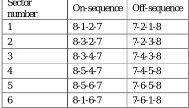
turned on. It can be seen that the chopping frequency of each phase of the inverter is equal to half of the sampling frequency. Table-2 depicts the switching sequence for all the sectors.
Table - 2 Switching sequences for two-level inverter in all the sectors for Space Vector Modulation Sector
number On-sequence Off-sequence 1 8-1-2-7 7-2-1-8
2 8-3-2-7 7-2-3-8
3 8-3-4-7 7-4-3-8
4 8-5-4-7 7-4-5-8
5 8-5-6-7 7-6-5-8
Volume 2, Issue 8, August 2013
Page 169
One of the important advantages of the space vector PWM over the sine-triangle PWM is that it gives nearly 15% more output voltage compared to the latter, while still remaining in modulation. Space vector modulation can also be regarded as the as a carrier based PWM technique with the modification that, the reference waveform has triplen harmonics in addition to the fundamental.Implementation of SVPWM
The conventional implementation of the space vector PWM involves the following steps: 1.Sector identification
2.Calculation of the active vector switching time periods
T
1 andT
2 using eqn.2.8.3.Translation of the active vector switching time periods T1 and T2 into the inverter leg switching timings ga
T ,Tgb andTgc. 4.Generation of the gating signals for the individual power devices using the inverter leg switching timingsTga,Tgb
andTgc.
Therefore, owing to this basic approaching manner of the conventional space vector PWM method, the overall process of this algorithm is complex and the implementation is formidable.
A simple and elegant algorithm is presented in which does not require the sector information and the angle ‘’ (the angle subtended by the reference vector with respect to the beginning of the sector in which the tip of the reference vector is situated). The algorithm proposed in is based on the instantaneous reference values of the phase voltages only. This algorithm is based on the concept of “Effective time” which is the time duration for which the load is connected to the supply. This algorithm reduces the execution time by more than 25% while the memory requirement is reduced to 15% compared to the conventional PWM method. The task of generating the gating signals is accomplished naturally and automatically with this algorithm. This algorithm is extended for the dual inverter scheme proposed in this thesis.
4. MODELLING OF CASE STUDY
DTC-SVM BASED ON INPUT-OUTPUT LINEARIZATION A. Model of Induction Motor
Under assumption of linearity of the magnetic circuit neglecting the iron loss, a three-phase IM model in a stationary DQ – axes reference with stator currents and flux are assumed as state variables, is expressed by
(9)
(10)
(11)
Where are respectively the axes of the stator flux, stator voltage and stator current vector components, is the rotor electrical angular speed, are the stator, rotor, and magnetizing inductances, respectively, , are the stator and rotor resistances, respectively. The electromagnetic torque in the induction motor can be expressed as
(12)
Where is the number of pole pairs
B. DTC-SVM Based on Input-Output Linearization
The DTC-SVM scheme is developed based on the IM torque and the square of stator flux modulus as the system outputs;
Volume 2, Issue 8, August 2013
Page 170
Stator voltage components defined as system control inputs and stator currents as measurable state variables.Let the system output be
(13)
Define the controller objectives as
(14)
Where , are reference value of electromagnetic torque and stator flux, respectively. According to (9)–(14), the time derivative of E is as (15)
(15)
Where
According to , the characteristic
determinant of D is as follows:
(16)
From (16), D is a nonsingular matrix since the inner product of stator flux vector and rotor flux vector cannot be physically zero. Based on input-output feedback linearization, the following control inputs are introduced:
(17)
Where are the auxiliary control inputs and are defined based on the pole placement concept of the linear control systems so that
(18) Where C1 and C2 are positive constants.
Volume 2, Issue 8, August 2013
Page 171
5. Simulation Results
At steady state electromagnetic torque is approximately equal to zero. Low torque ripples occur. Phase current is sinusoidal and is used for magnetization. Stator flux is kept constant.
Fig: The motor speed, torque and stator currents of Induction Motor at steady state.
Fig: The input voltage, frequency. Torque and rotor speed of Induction Motor at steady state.
6. CONCLUSION
A novel DTC-SVM scheme has been developed for the IM drive system, which is on the basis of input-output linearization control. In this control method, a SVPWM inverter is used to feed the motor, the stator voltage vector is obtained to fully compensate the stator flux and torque errors. Furthermore, a robust full-order adaptive flux observer is designed for a speed sensor less DTC-SVM system. The stator flux and speed are estimated synchronously. By designing the constant observer gain matrix based on state feedback control theory, the robustness and stability of the observer systems is ensured. Therefore, the pro- posed sensor less drive system is capable of steadily working in very low speed, has much smaller torque ripple and exhibits good dynamic and steady-state performance.
REFERENCES
[1] I. Takahashi and T. Noguchi, “A new quick-response and high efficiency control strategy of an induction motor,” IEEE Trans. Ind. Appl., vol. IA-22, no. 5, pp. 820–827, 1986.
[2] Y. S. Lai and J. H. Chen, “A new approach to direct torque control of induction motor drives for constant inverter switching frequency and torque ripple reduction,” IEEE Trans. Energy Convers., vol. 16, no. 3, pp. 220–227, 2001. [3] S. Mir, M. E. Elbuluk, and D. S. Zinger, “PI and fuzzy estimators for tuning the stator resistance in direct torque
control of induction machines,” IEEE Trans. Power Electron., vol. 13, no. 2, pp. 279–287, 1998.
Volume 2, Issue 8, August 2013
Page 172
[5] A. Arias, J. L. Romeral, and E. Aldabas, “Fuzzy logic direct torque control,” in Proc. IEEE ISIE, 2000, vol. 1, pp.253–258.
[6] D. Seyoum, M. F. Rahman, and C. Grantham, “Simplified flux estimation for control application in induction machines,” in IEMDC’03, 2003, vol. 2, pp. 691–695.
[7] G. Xi, H. Gao, and W. Xu et al., “A method to determine gain matrix of stator flux full order observer,” J. Cent. South Univ. (Science and Technology), vol. 39, no. 4, pp. 793–798, 2008.
[8] J. Soltani1, G. R. A. Markadeh, and N. R. Abjadi3 et al., “A new adaptive direct torque control (DTC) scheme based-on SVM for adjustable speed sensorless inductibased-on motor drive,” in ICEMS 2007, Seoul, Korea, Oct. 8–11, 2007, pp. 497–502.
[9] A. Tripathi, A. Khambadkone, S. Panda, “Stator Flux Based Space – Vector Modulation and Closed Loop Control of the Stator Flux Vector in Over modulation Into Six – Step Mode”, IEEE Transactions on Power Electronics, Vol. 19, No. 3, May 2004, pp. 775 – 782.
[10]A. Tripathi, A. Khambadkone, S. Panda, “Dynamic Control of Torque in Over modulation and in the Field Weakening Region”, IEEE Trans. on Power Electronics, Vol. 21, No. 4, July 2006, pp. 1091 – 1098 .
[11]A. Tripathi, A. Khambadkone, S. Panda, “Predictive stator flux control with over modulation and dynamic torque control at constant switching frequency in AC drives”, 2002 IEEE Industry Applications Conference, 37th IAS Ann. Meet., 13 – 18 October 2002, Vol. 3, pp. 2080 – 2085.
[12]D. C. Lee, G. M. Lee, “A Novel Over modulation Technique For Space Vector PWM Inverters”, IEEE Transactions on Power Electronics, Vol. 13, Issue: 6, November 1998, pp. 1144 – 1151.
[13]A. Diaz, E. G. Strangers, ”A Novel Wide Range Pulse Width Over modulation Method [for Voltage Sourced Inverters]”, Applied Power Electronics Conference and Exposition, APEC 2000, 15th Annual IEEE, Vol. 1, 6 – 10 February 2000, pp. 556 – 561.
Author
P.SanthiKumar was born inPrakasam, India. He received the B.Tech (Electrical and Electronics Engineering) degree from the Jawaharlal Nehru Technological University in 2003. M-Tech (Power Electronics and Industrial Drives), from satyabhama university in 2010. His area of interested in Power Electronics applications in Electrical Machines. He was working as an Associated Professor in Department of Electrical and Electronics Engineering in NIE College.