Volume 2, Issue 3, March 2013
Page 584
ABSTRACT
Now-a-days most of the datapath appliances are designed and developed using the basic FPGA architectures. In this paper, a new architecture is proposed based on design of FPGA. This design issue is of vital so as to fix the FPGA architecture fit for a datapath circuit functioning. The proposed architecture has a hierarchical interconnection structural design through which a chip with an array of 16*16 LC is considered so that the interconnection of the proposed design is tested, and certain circuit sample from the design of a practical digital system is thus implemented. A CMOS process layout with 0.6um is integrated with the proposed chip architecture. CAD tools are used for testing this chip on a platform with test hardware. After testing the end result thus meet the design constraints, and shows that the expected programming and the test function can be achieved by the desired circuit. The final result thus proves that the proposed design is accurate.
Keywords: FPGA, CAD tools, CMOS, LC
1. INTRODUCTION
In order to improve the performance of FPGA time to time quite a few new designs have been designed [1, 6]. To design such a new FPGA architecture a lot of effort have been made and mostly for datapath appliances. Earlier in paper titled “an extended logic for data path applications” an introduction of a high-speed programmable logic cell (ELC) for datapath [6] in which a new FPGA architecture i.e., FDEGA2000 has been designed, that describes the LC (this can work in either static mode or dynamic mode to implement circuits such as ALU efficiently) [11]. As mentioned above [7] focuses on the combinational logic design of LC only, and the FDEGA2000 in [11] meets with challenges in developing effective mapping, P&R algorithms which can utilize the logical flexibility brought about by the dual-mode LC.
En route for building consistent high technology electronic products with a high degree of testability the Boundary-scan has rapidly become the technology of choice. In view of the fact that from the time it was introduced as an industry standard in the year 1990, boundary-scan has enjoyed growing popularity for board level manufacturing test applications [3,2]. Earlier to do the same traditional board test applications are to be used that are now substituted with the boundary-scan due to its low-cost and IC level access capabilities. It now expanded beyond the traditional board test applications into product design and service. With the development of IC fabrication technology, package technology and PCB technology, traditional test methods have met their limits [9]. BSCAN test has become more and more popular, especially after the publication of Std. IEEE1149.1 by IEEE. It has been adopted by numerous ASIC and FPGA manufacturers [3] [12].
The LC of FDEGA is optimized for datapath implementation, and can be programmed as either combinational or sequential device. This design emphasizes the function of PCB level test while considering chip level test function as well. The FDEGA is fabricated in 0.6um 2 metal layer standard CMOS process.
Field Programmable Gate Arrays (FPGAs) are widely applied for implementation of digital systems [4], a large fraction of its application lies in datapath circuit, prevailing in fields as diverse as telecommunications, high speed image processing, and digital signal processing. Although there are several commercial architectures available [2]-[3], they are designed mainly for general application, which limits their performance in datapath application.
BSCAN is a widely practiced test methodology that is reducing costs, speeding development, and improving product quality for electronics manufacturers around the world. By relying on an industry standard, IEEE 1149.1, it is relatively quick, easy, and inexpensive to deploy a highly effective test procedure. Indeed, for many of today’s PCBs, there is little alternative because of limited access to board-level circuitry. Different from conventional test method with
Recent Trends in FPGA Architecture for
Testing the Data path Using BSCAN
Prathyusha.K1, G. Sowmya Bala2, Dr. K.Sreenivasa Ravi3
1
Assistant Professor, Dept. of ECM. K.L.University, Vaddeswaram, A.P, India,
2
Assistant Professor, Dept. of ECM. K.L.University, Vaddeswaram, A.P, India,
3
Volume 2, Issue 3, March 2013
Page 585
physical contact, boundary scan technology inserts a shift register chain between pins and the “system” logic of chip to apply test vector and monitor the response. [8] [10]. Four or five dedicated test pin, named TAP (Test Access Port) are used in IEEE1149.1 to implement a set of test functions, providing test access at chip level, PCB level and system level[13]. In addition, the boundary scan test standard can be extended to realize more complicated test task such as BIST (Build-In Self Test) and single-step debugging of digital system.FDEGA (Field-programmable Datapath Enhanced Gate Array) is a new FPGA architecture design by our group. In-system test and in-system programming are important in its application .This paper introduces a boundary-scan test. BSCAN circuit in brief, designed for our FDEGA chip. We chose the test function from the specification of Std. IEEE 1149.1 for the practical application of FDEGA and added the programming function into boundary-scan circuit for the in-system programming of FDEGA.
2. LOGIC
CELL ARCHITECTUREThe logic cell (LC), as shown in figure 1, aiming at the implementation of datapath application is the fundamental building block of this new programmable architecture. The logic function kernel of LC, as shown in shaded area, is based on the ELC architecture with 4 1-bit LUTs (Look Up Table) enhancing its logic flexibility. It can implement 1-bit full adder (FA) or 1-bit multiplier with fast carry chain in both vertical and horizontal direction, as well as any 3-input logic or some 4-input logic. Most of the reported logic cell designs (including our previous design in [11]) consist of a programmable.
Combinational logic part and a sequential logic part following it. In such architectures, the ratio of combinational logic resource to sequential logic resource is fixed, so that one kind of resource may be wasted when the capacity of the whole FPGA is limited by the other kind of resource. To have a flexible Combinational-sequential rate, our LC can be programmed to implement sequential logic, instead of having a hard sequential part in it. The switch array in LC form feedback loops to implement master-slave flip-flop. Net 1, 2 and 3 form the master stage, which output to net 4 from net 2. Signal on net “ck” control this stage to be transparent through path 1, 2, or latch signal in loop 2, 3. Net 4, 5, 6, 7 and 8 form the slave stage. Signal on net “ck” control it to be transparent through 4, 5, 6, 7 or latch signal with 5, 6, 7, 8
Figure 1 Design of Programmable Logic Cell (LC)
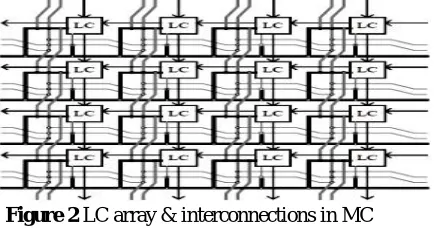
3. INTERCONNECTION
A
RCHITECTUREFDEGA has a hierarchical interconnect design, consists of three different levels of programmable interconnect resource: short line, dividable long ling and long line. Every LC has 8 short lines routing to the 8 LC’s in its nearest neighbourhood. There is only one switch on every short line, which gives a high-speed local connection. For datapath applications, which can best utilize local connections, this high speed is especially desirable and useful.
Volume 2, Issue 3, March 2013
Page 586
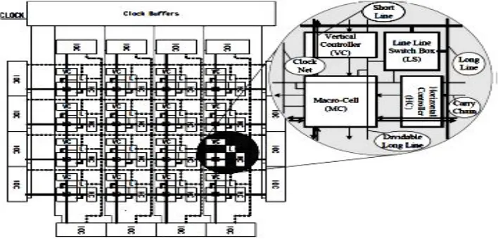
Dividable long lines form a mesh-like interconnection resource, which consists of segments that span the length of 4 LC’s, and can be connected by programmable switches at the ends of each segment to form longer lines. Long lines that span the whole length of gate array are available to every MC (An MC includes 4*4 LC’s, which will be introduced in the next section) to connect LCs over long distance with higher speed than dividable long lines. Each IOC controls 4 programmable IO pads, thus the FDEGA provides 64 programmable IO pads for circuit implementation use in total.
Figure 3 Structure of programmable array
4. BSCAN (BOUNDARY SCAN)
BScan is a technology used to test, program and debug printed circuit boards (PCBs). Boundary Scan is often used to increase overall board test coverage by complementing traditional test methods like In-Circuit Test (ICT) and Automated Optical Inspection (AOI). BScan Testing was created to test printed circuit boards for interconnect errors such as: shorts, opens and stuck-at faults that are typically caused by problems in the manufacturing process. BScan can also be used to functionally test devices such as: RAM, FLASH, I/O and Logic. Boundary Scan uses a method known as “pins-out” testing. Pins-Out testing is implemented on an IC that supports Boundary Scan by including a test cell on each of the IC’s pins. These cells contain test logic that can control signals into and out of each of the IC’s external pins. Using this technique, signals can be sent between chips that have connected pins (or nets). The diagram to the left below shows how two such devices can be used in a test for shorts circuit failures. To allow control of the on-board BScan cells, each device has a serial bus comprised of at least four standard signals: TDI, TDO, TMS and TCK. An external BScan tester can be connected to these pins and controls the tests being sent to the board via host based
software. BScan test is more valuable for FPGA’s than for ASIC’s in improving the testability of the chip, for the
higher complexity of FPGA testing. Another important reason why BScan is widely adopted in FPGAs is that it can help to achieve JTAG programming and In-system programming (ISP).
Volume 2, Issue 3, March 2013
Page 587
5. TOP-LEVEL DESIGN
The architecture of boundary scan circuit consists of 5 modules: TAP, TAP controller, registers, instruction decoder and ram controller, as shown in figure 5. The test instructions, programming instructions, test data and programming data are transferred through TAP, using a simple serial communication protocol. TAP controller handles the process of this communication, and synchronizes the operation of other modules.
Figure 5 Modules of boundary scan circuit
The instruction decoder generates control signals according to the instructions received from TAP to perform testing or programming. Registers include instruction register (IR) and data registers (DR). IR receives instruction from TAP serially, and then put it to instruction decoder in parallel. DR gets data from TAP and use it in the testing or programming under the control of TAP controller and instruction decoder. RAM controller generates signals to control RAM access such as write, read and erase.
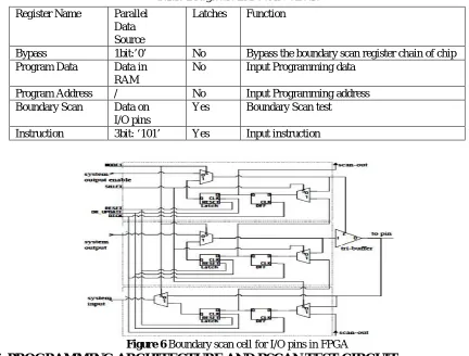
The I/O pins in FPGA are different from those in normal ASIC’s. Special design was adopted for the programmable bi-directional tri-state pins in FPGA (as shown in figure 6), which consists of 3 cells. This cell can observe and control the state of the I/O pins by the input, output and output enable signal of the pins. The structure of each register is shown in table 1 below.
Table 1 Registers in BSCAN Circuit
Figure 6 Boundary scan cell for I/O pins in FPGA
6. PROGRAMMING ARCHITECTURE AND BSCAN TEST CIRCUIT
Register Name ParallelData Source
Latches Function
Bypass 1bit:’0’ No Bypass the boundary scan register chain of chip Program Data Data in
RAM
No Input Programming data
Program Address / No Input Programming address Boundary Scan Data on
I/O pins
Yes Boundary Scan test
Volume 2, Issue 3, March 2013
Page 588
The FDEGA chip also includes programming control circuit and BScan test circuit designed for its practical application. All the configuration bits in FDEGA together form an SRAM with size about 24k bit, they are organized in rows and columns like regular SRAM (as shown in figure 7 below), and configured by two shift registers. One is “Address Register” that selects a certain row to be configured according to the address shifted into it serially, and the other is “Data Register” that performs parallel output to each corresponding column after data has been shifted in serially.A programming control circuit generates data, address and other signals to control the two registers with the cooperation of JTAG programming circuit, direct programming pad or E2PROM, selectively, according to the user’s choice. BScan test is more valuable for FPGA’s than for ASIC’s in improving the testability of the chip, for the higher complexity of FPGA testing.
Another important reason why boundary-scan is widely adopted in FPGA’s is that it can help to achieve JTAG programming and In-system programming (ISP). Our FDP chip supports the IEEE 1149.1 boundary-scan design as well as JTAG programming.
Figure 7 Programming architecture
7. I
MPLEMENTATION ANDT
ESTR
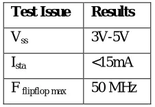
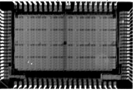
ESULTThe FDEGA is fabricated in 0.6um 2 metal layer standard CMOS process. (The photo of the chip is shown in figure 8 below). The chip is tested on a platform with test hardware and CAD tools, and the main parameters got from the test are shown in table 2. The chip can work under power supply of 3V to 5V; the static operation current is less than 15mA. The circuit implemented in FDEGA can run at the highest speed of 50MHz.
Table 2 FDEGA test Results
Test Issue Results
Vss 3V-5V
Ista <15mA
F flipflop max 50 MHz
First, the programming function of programming control circuit is verified, and the result shows that it can configure the SRAM in FDEGA reliably. Then the programmable interconnection, switch box and programmable I/O cells are tested. We link two I/O pads directly together, one programmed as input pad and the other as output pad, with the programmable interconnection resource.
Volume 2, Issue 3, March 2013
Page 589
Table 3 Circuit Implementation
To test the FDEGA architecture as a whole, we used the FDEGA chip to implement several larger digital circuits that take up about tens of LC’s. We implemented a 4-bit multiplier, which occupies an MC, 8 input pads and 7 output pads. We have also chosen two circuits from practical digital system design, which comprise of control logic circuit, encoding circuit, random combinational module and FSM (Finite State Machine).
Figure 8 Photo of FDEGA
All the three circuit-samples implemented have performed entirely correct functions. This result testifies that the LC, interconnection, carry chain and MC architecture can work together and function properly, to implement practical digital circuit. The boundary scan test circuit in FDEGA was also tested, and all of its function is proved to be correct.
8. CONCLUSION
The design, implementation and test result of a novel FPGA architecture are described. Our design consideration of this FPGA is focused on datapath circuit application. LC architecture has been introduced on the basis of our earlier research. The LC can be programmed to implement sequential logic without a hard sequential part in it. A 3-level hierarchical interconnection architecture has been designed. A chip with 16*16 LC array is designed and fabricated in 0.6 CMOS process. The test result of FDEGA chip shows that the logic function of our LC’s, carry chain and interconnection resources is correct. And the ability of FDEGA to implement digital circuit has also been verified by several different circuit implementations. An external BScan is used as a tester. The design of our new FPGA architecture has been proved correct in test. Successfully designed an FPGA chip, and gain considerable understanding of the design issues of FPGA. The prevailing process used in FPGA design has scaled down to less than 0.35um, which provides higher logic density and will influence the design of logic cell and interconnection architecture.
9. FUTURE SCOPE
It will focus on improving our design with more advanced process and consider the design issues brought about by the better process technology and testing.
Type Circuit
Comb1 A 4-input and gate
Comb2 A 1-bit FA
Comb3 A 1-bit multiplier
Comb4 A 4-bit FA
Seq 1 A D-flip flop
Seq 2 A D-flip flop with asynchronous set
Volume 2, Issue 3, March 2013
Page 590
REFERENCE
[1] A. Marquardt, V. Betz, Speed and Area Tradeoffs in Cluster-Based FPGA Architectures, IEEE Trans. VLSI System, vol.8, Feb. (2001), p.84–93
[2] Altera Corp., Data book (Altera Corp., San Jose, CA, 1996)
[3] Xilinx Corp., The Programmable Logic Data Book (Xilinx Corp., San Jose, CA, 1998)
[4] S. Brown, et al, Field-Programmable Gate Arrays (Kluwer, Norwell, 1992) [5] P.Chow, et al, The Design of an SRAM-Based Field-Programmable Gate Array—Part I: Architecture, IEEE Trans. VLSI System, vol.7, Jun. (1999), p.191-197
[5] P.Chow, et al, The Design of an SRAM-Based Field-Programmable Gate Array—Part II: Circuit Design and Layout, IEEE Trans. VLSI System, vol.7, Sep. (1999), pp.321-330
[6] Guo Binlin, Tong Jiarong, ELC: An Extended Logic Cell For Datapath Application, CAD/Graphics (2001) [7] Colin M. Maunder & Rodham E. Tulloss, The Test Access Port and Boundary Scan Architecture, (IEEE Computer
Society Press, Washington, USA, 1990), pp. 33-170
[8] Harry Bleeker, et al, Boundary-Scan Test: A Practical Approach (Kluwer Academic, Netherlands, 1993), [9] Kenneth P. Parker, The Boundary Scan Handbook, (Kluwer Academic, Boston, 1992), pp.11-111
[10]Guo Binlin, Tong Jiarong, FDP2000: Design and Implementing for a High Performance FPGA (2002) Fig 5. Photo of FDEGA
[11]Altera Corp., Data book, (Altera Corp, San Jose, CA, 1996)